SMART Pressure Transmitter
FT3351 Series User Manual July.2022
www.Faraboard.com 4 | P a g e
FAHM Co.
Industrial Automation
Doc. FT3351Rev1401-05
1.Introduction
1.1 Preface
Welcome to use smart pressure transmitter, please read this manual before working with the
product. For personal and system safety, and for optimum product performance, make sure you
thoroughly understand the contents before installing, using, or maintaining this product.
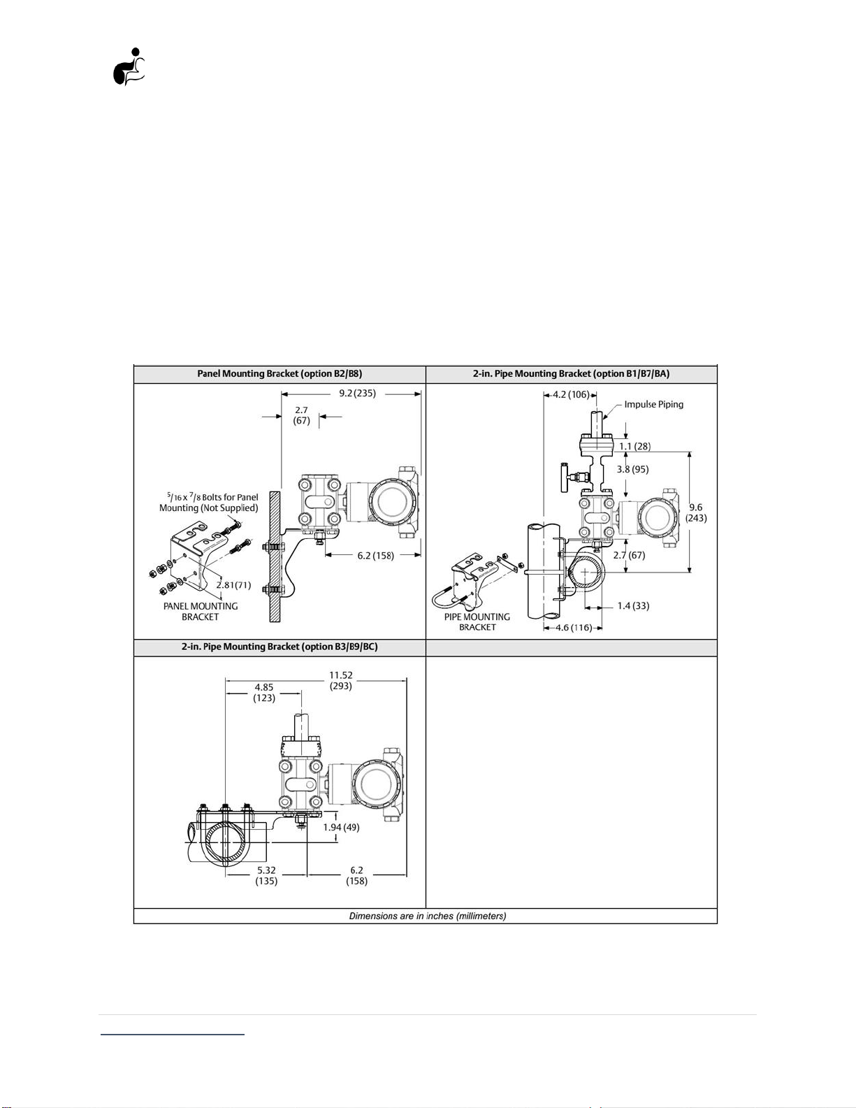
1.2 Transmitter overview
The FT3351 are used to measure differential pressure, gauge pressure, absolute pressure
parameters for gas, liquid, vapor, widely applied in petroleum, metallurgy, chemicals, power,
light industry, mechanical and environmental protection fields. The FT3351 utilizes capacitance
sensor technology and piezo resistive sensor technology for pressure measurements. The major
components of the FT3351 are the sensor module and the electronics housing. The sensor
module contains the oil filled sensor system (isolating diaphragms, oil fill system, and sensor) and
the sensor electronics. The sensor electronics are installed within the sensor module and include
a temperature sensor, a memory module, and the capacitance or resistance to digital signal
converter (A/D converter). The electrical signals from the sensor module are transmitted to the
output electronics in the electronics housing. The electronics housing contains the output
electronics board, the optional local operator Interface (LOI) buttons, and the terminal block.
Powerful interface features without hand held communicator are able to ensure good
interaction. For the FT3351 design, pressure is applied to the isolating diaphragms then the oil
deflects the center diaphragm and as a result the sensor element capacitance or resistance will
be changed. This signal is then changed to a digital signal in the A/D converter. The
microprocessor takes the signals from the pressure and temperature sensor and calculates the
correct output of the transmitter. LCD indicator can display the digital pressure, temperature,
current some kinds of physicals and 0-100% analog indication. In case of non-standard pressure
source, parameter setting zero shift, range setting damping adjustment can be done by press key
button; and also recalibration on the transmitter are greatly convenient for on-site calibration
(see Figure 1) .