CALIBRATIONS / ADJUSTMENTS
Equipment Required for Calibration:
• Pneumatic Supply capable of delivering up to 150 psig.
• Current Supply capable of delivering up to 50 mA.
• Voltage Supply capable of delivering up to 10 VDC.
• Pressure Gage capable of a digital readout up to 50 psig
with an accuracy of .1%.
• Digital Volt Meter capable of a readout up to 30 mA or
10 VDC with an accuracy of .02%.
The following adjustments are provided:
Full Range Operation
Forward/Reverse Mode
Calibration - Zero and Span
FULL RANGE OPERATION
Forward Acting Mode Adjustment
NOTE: Air Supply must be on before adjustments are
made.
1. Connect the input signal to the transducer as shown
in Figure 6. “Electrical Connections.”
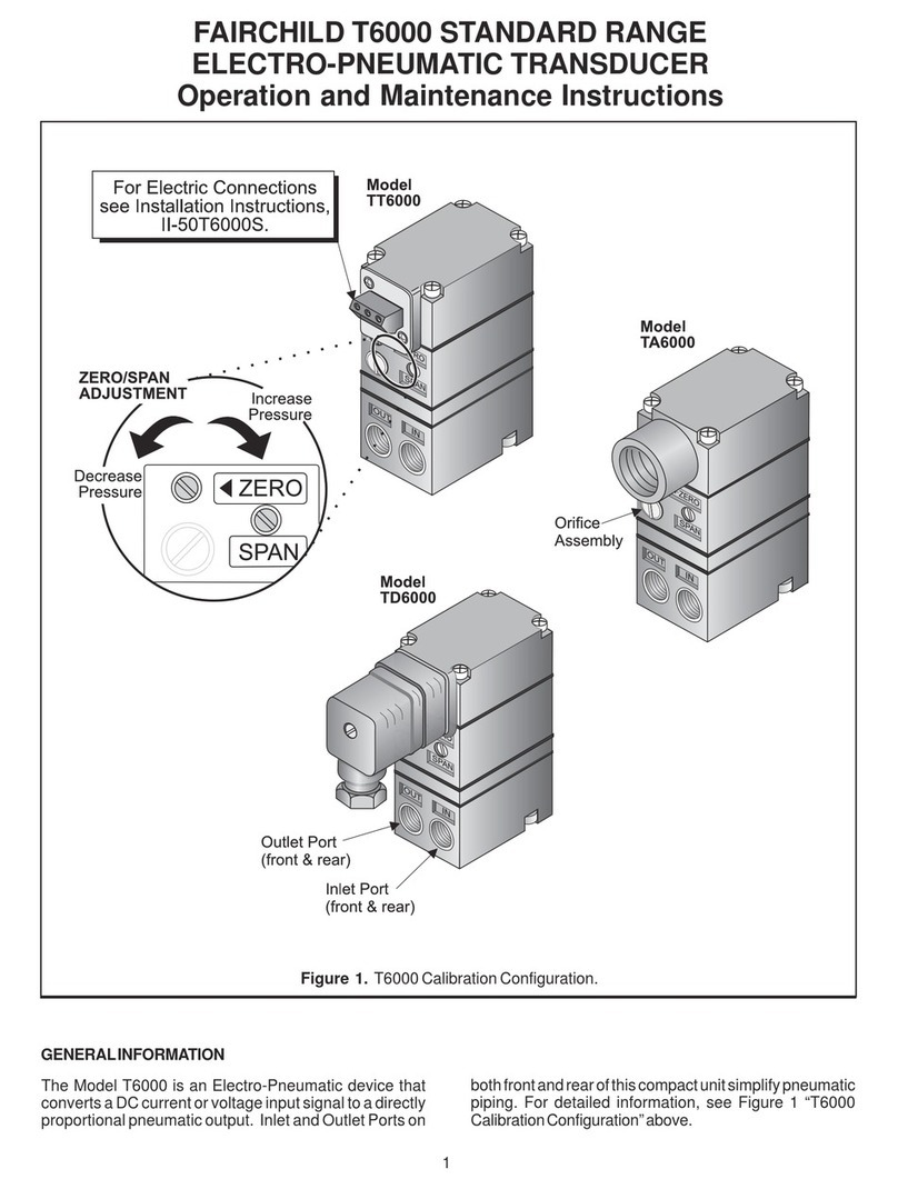
• Forward Acting Calibration-Zero
2. Apply the minimum input signal and adjust the Zero
screw for minimum output pressure. Turn screw
counterclockwise to increase pressure and clock-
wise to decrease pressure.
• Forward Acting Calibration-Span
3. Apply the maximum input signal and adjust the Span
screw on the potentiometer for maximum output
pressure. Turn screw clockwise to increase pres-
sure and counterclockwise to decrease pressure.
4. Repeat steps 2-3 until the desired output range is
obtained. For more information, see Figure 7. “T5220/
TXPD5220Calibration Configuration.”
Reverse Acting Mode Adjustment
NOTE: Intrinsically safe units cannot be set for re-
verse acting mode in field.
5. Connect the input signal to the transducer as shown
in Figure 6. “Electrical Connections.”
• Reverse Acting Calibration-Zero
6. Apply the minimum input signal and adjust the Zero
screw for maximum output pressure. Turn screw
counterclockwise to increase pressure and clock-
wise to decrease pressure.
• Reverse Acting Calibration-Span
7. Apply the maximum input signal and adjust the Span
screw on the potentiometer for minimum output pres-
sure. Turn screw counterclockwise to increase pres-
sure and clockwise to decrease pressure.
8. Repeat steps 6-7 until the desired output range is
obtained. For more information, see Figure 8. “T5200/
TXPD5200 Calibration Configuration.”
Figure 7. T5220 / TXPD5220 Calibration Configuration.
5
