manuals.online logo
Brands
  1. Home
  2. •
  3. Brands
  4. •
  5. Fairchild
  6. •
  7. Transducer
  8. •
  9. Fairchild T6000 User manual

Fairchild T6000 User manual

FAIRCHILD T6000 Electro-Pneumatic Transducers
Standard and Extended Ranges
Installation Instructions
GENERAL INFORMATION
The Model T6000 can be mounted directly onto a flat surface using two 10-32 screws.
The Model T6000 is supplied with a Mounting Kit 16799-1 for Panel or Wall Mounting. For detailed information,
see page 2.
Figure 1. TA6000 Outline
Dimensions
Note: Unused IN and OUT
Ports are plugged (typical)
Figure 2. TT6000 Outline
Dimensions
Figure 3. TD6000 Outline
Dimensions
Figure 4. TR6000 Outline
Dimensions
Installation
The Model T6000 is supplied with a DIN Rail Mounting Kit
16893. For detailed information, see Figure 6. A
Mounting Kit 19254-1 is available when installing the unit
on a 2" pipe, see Figure 7.
Figure 5. Mounting Kit 16799-1 (Included with Unit)
NOTE: The TR6000Transducerisdesignedfor usewith
the TR Rack Kit. Physically, it is the same as the TT6000
(Terminal Block) Unit except that the terminal block has
been rotated to the rear. For detailed information, see
Figure 4. “TR6000 Outline Dimensions” on page 1.
Figure 6. DIN Rail Mounting Kit 16893 (Included with Unit)
Figure 7. Mounting Kit 19254-1 (Sold Separately)
2
Pneumatic Connection
Cleanall pipelines to remove dirt and scale before installation.Apply
a minimum amount of pipe compound to the male threads of the
fitting only. Do Not use teflon tape as a sealant. Start with the third
thread back and work away from the end of the fitting to avoid
contaminating the transducer. Install the transducer in the air line.
The inlet and outlet ports are labeled on the ends of the transducer.
Tightenconnections securely. Avoidundersized fittings that will limit
the flow through the transducer and cause pressure drop down
stream.
NOTE: Oil free air is required. Use a filter to remove dirt and
liquid in the air line ahead of the transducer. If an air
line lubricator is used, it MUST be located down-
stream to avoid interference with transducer perfor-
mance.
The user is responsible for insuring that the environ-
ment in which the unit will be installed and the
operating gas are compatible with the materials in the
transducer.
Electric Connection
Make connections as shown in Figure 8.
CAUTION: Effective November 1997 (DATE CODE NE), the DIN
Connector terminal connections have been changed. The ground
connection has been moved from terminal #3 to the ( ) terminal.
When replacing an existing unit, correct wiring on the mating
connector.
Wiring in Hazardous Areas
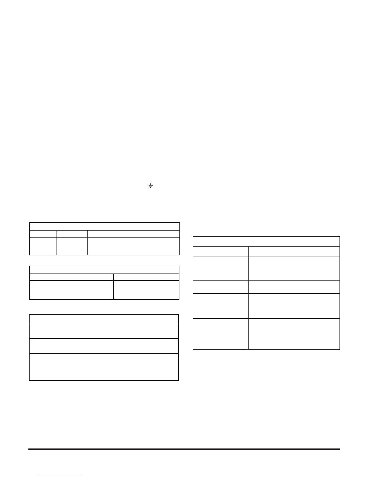
Table 1. Hazardous Location Wiring Practices.
Country Agency Code
U.S.
Canada
Europe
FM
CSA
ATEX
ANSI/ISARP 12.6 &ANSI/NFPA70
CEC Part 1
EN 50 039, EN 60079-14, IEC 60079-14
Intrinsically Safe Connections
Table 2. Intrinsically Safe Installation Drawings.
Underwriting Group Drawing Number
FM (Factory Mutual)
CSA (Canadian Standards)
ATEX
EC-16984
EC-18005
EC-18007
Limitations/Exceptions
Type 3R - TAF, TDF upright position
TFA- CL I, Div 2 wiring per NECANSI/NPFA70 for installation
without wiring parameters. TDF, TTF, TRF require an enclosure.
For dry locations and voltages less than 60Vdc, TTF & TRF
units must be in an enclosure.
Where loop voltages exceed 60Vdc (dry locations) or 30Vdc
(potentially damp locations), the TTF and TRF versions
must be installed meeting the electrical shock and fire
protection requirements of ANSI/ISA S82.01.
MAINTENANCE
To clean the Orifice, use the following procedure:
1. Shut off the valve that is supplying air to transducer.
It is not necessary to remove the Transducer from
the air line.
2. Remove the Orifice Assembly from the unit. For
detailed information see Figure 1 “T6000 Calibration
Configuration on page 1.
3. Clean with alcohol and dry with compressed air.
NOTES:
Parts must be completely dry before reassembling.
If the standard maintenance procedure does not
correct the trouble, install the appropriate Service
Kit below:
16798-1 (3-15, 3-27 & 6-30 psig
Standard Range)
18238-1 (0-30 psig Extended Range)
18239-1 (0-60 psig Extended Range)
18240-1 (0-120 psig Extended Range)
18039-1 (Explosion-Proof Base)
Service Kits also include Gasket, O-Rings, and
Membranes to replace "W" Option product.
TROUBLE-SHOOTING
Table 1. Trouble-Shooting.
Problem Solution (check)
No Output Supply Pressure
Clogged Orifice
Input Signal
Leakage Pneumatic Connections
Low or Improper
SpanAdjust
Zero and Span Adjust
Supply Pressure Low
Output Leakage
Erratic Operation DC Signal
Loose Wires or Connections
Liquid in Air Supply
Dirt in Magnet Gap
WARNING: Failure of Transducer could result in out-
put pressure increasing to supply pres-
sure possibly causing personal injury or
damage to equipment.
3
CALIBRATIONS / ADJUSTMENTS Reverse Acting Mode Adjustment
Equipment Required for Calibration:
• Pneumatic Supply capable of delivering up to 150 psig.
•Current Supply capable of delivering up to 60 mA.
• Pressure Gage capable of a digital readout up to 50 psig
with an accuracy of .1%.
• Digital Volt Meter capable of a readout up to 60 mAwith
an accuracy of .02%.
FULL RANGE OPERATION
CAUTION: Over-ranging the Zero Screw can damage unit.
Forward Acting Mode Adjustment
1. Connect the input signal to the transducer as shown
in the Installation Instructions, II-50T6000X.
• Forward Acting Calibration-Zero
2. Apply the minimum input signal and adjust the Zero
screw for minimum output pressure. Turn screw
clockwise to increase pressure and counterclock-
wise to decrease pressure.
• Forward Acting Calibration-Span
3. Apply the maximum input signal and adjust the Span
screw for maximum output pressure. Turn screw
clockwise to increase pressure and counterclock-
wise to decrease pressure.
4. Repeat steps 2-3 until the desired output range is
obtained. For detailed information, see Figure 1
“TXPD6000 Calibration Configuration” on page 1.
5. Connect the input signal to the transducer as shown
in the Installation Instructions, II-50T6000X.
• Reverse Acting Calibration-Zero
6. Apply the minimum input signal and adjust the Zero
screw for maximum output pressure. Turn screw
clockwise to increase pressure and counterclock-
wise to decrease pressure.
• Reverse Acting Calibration-Span
7. Apply the maximum input signal and adjust the Span
screw for minimum output pressure. Turn screw
clockwise to decrease pressure and counterclock-
wise to increase pressure.
8. Repeat steps 6-7 until the desired output range is
obtained. For detailed information, see Figure 1
“TXPD6000 Calibration Configuration” on page 1.
SPLIT RANGE OPERATION
All units have the capability to be split ranged or set for any
output in the range as long as the Output Span is equal to
or greater than the minimum Span.
ATEX Directive - Special
Conditions for Safe Use:
The enclosure is manufactured from aluminum alloy. In rare
cases, ignition sources due to impact and friction sparks could
occur. This shall be considered when the equipment is installed in
locations that specifically require Group II, category 1G equipment.
LEGAL NOTICE:
The information set
forth in the foregoing
Operation and Mainte-
nance Instructions
shall not be modified
or amended in any re-
spect without prior
written consent of
Fairchild Industrial
Products Company. In
addition, the informa-
tion set forth herein
shall be furnished with
each product sold in-
corporatingFairchild's
unit as a component
thereof.
II-5T6000ES
Litho in USA
Rev. F 06/07

Other manuals for T6000

2

This manual suits for next models

3

Other Fairchild Transducer manuals

Fairchild T7900 User manual

Fairchild

Fairchild T7900 User manual

Fairchild TT7800 Manual

Fairchild

Fairchild TT7800 Manual

Fairchild T6100 Manual

Fairchild

Fairchild T6100 Manual

Fairchild T6000 User manual

Fairchild

Fairchild T6000 User manual

Fairchild T7800 Series Manual

Fairchild

Fairchild T7800 Series Manual

Fairchild T6000 Guide

Fairchild

Fairchild T6000 Guide

Fairchild T7800 Series General instructions

Fairchild

Fairchild T7800 Series General instructions

Fairchild T79 Series Operating and maintenance manual

Fairchild

Fairchild T79 Series Operating and maintenance manual

Fairchild T5220 Manual

Fairchild

Fairchild T5220 Manual

Fairchild T5200 Series Manual

Fairchild

Fairchild T5200 Series Manual

Fairchild TXI7800 Manual

Fairchild

Fairchild TXI7800 Manual

Popular Transducer manuals by other brands

Simrad ES120-7C -  REV D Dimensions

Simrad

Simrad ES120-7C - REV D Dimensions

Evco EVHP503 Getting started

Evco

Evco EVHP503 Getting started

Siemens Echomax XCT-8 instruction manual

Siemens

Siemens Echomax XCT-8 instruction manual

UIS WAT-110 user manual

UIS

UIS WAT-110 user manual

LEM IT 60-S user guide

LEM

LEM IT 60-S user guide

Alstom i4MC manual

Alstom

Alstom i4MC manual

HBM T12 Mounting instructions

HBM

HBM T12 Mounting instructions

WIKA WUC-10 operating instructions

WIKA

WIKA WUC-10 operating instructions

American Printing House for the Blind Braille Plus 18 user guide

American Printing House for the Blind

American Printing House for the Blind Braille Plus 18 user guide

B-K Medical 8824 user guide

B-K Medical

B-K Medical 8824 user guide

Ashcroft CXLdp Installation and maintenance sheet

Ashcroft

Ashcroft CXLdp Installation and maintenance sheet

FTS SDI-PT-KEL user manual

FTS

FTS SDI-PT-KEL user manual

OJ Electronics PTH-3202-DF instructions

OJ Electronics

OJ Electronics PTH-3202-DF instructions

Zimmer PRO -V manual

Zimmer

Zimmer PRO -V manual

Lumel P30O user manual

Lumel

Lumel P30O user manual

SonoSite TEExp user guide

SonoSite

SonoSite TEExp user guide

ETH-messtechnik DRVL Operator's manual

ETH-messtechnik

ETH-messtechnik DRVL Operator's manual

JUMO HC103 operating instructions

JUMO

JUMO HC103 operating instructions

manuals.online logo
manuals.online logoBrands
  • About & Mission
  • Contact us
  • Privacy Policy
  • Terms and Conditions

Copyright 2025 Manuals.Online. All Rights Reserved.