Fairmount Tools 31471 User manual

10 TON HYDRAULIC
GEAR PULLER
INSTRUCTIONS
Item #31471

2Eastwood Technical Assistance: 800.544.5118 >> techelp@eastwood.com
The FAIRMOUNT 10 TON HYDRAULIC GEAR PULLER is designed for universal use with versatile 2 or
3 arm configurability. Reversible arm positing accommodates outside or inside pulls equally well. The
self-contained Hydraulic Ram design provides greatly amplified pulling force. This tool, constructed of
robust, high-strength steel alloy forgings, will provide years of reliable service.
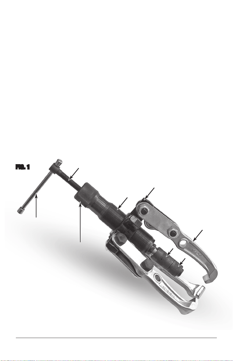
CONTENTS
(3) Puller Arms - A
(6) Nut, Bolt & Washer Sets - B
(6) Puller Arm Links - C
(1) Center Yoke - D
(1) Drive Ram - E
(1) Drive Ram Button - F
(1) Drive Ram Button Extension - G
(1) Heavy-Duty, Blow Molded Case
DANGER indicates a hazardous situation which, if not avoided, will result in death or serious injury.
WARNING indicates a hazardous situation which, if not avoided, could result in death or serious injury.
CAUTION used with the safety alert symbol, indicates a hazardous situation which, if not avoided,
could result in minor or moderate injury.
NOTICE is used to address practices not related to personal injury.
SAFETY INFORMATION
The following explanations are displayed in this manual, on the labeling, and on all other information
provided with this product:
A
A
BD
C
C
EG F
Stem
“T” Handle Plunger
✓
✓
✓

To order parts and supplies: 800.345.1178 >> eastwood.com 3
READ INSTRUCTIONS
• Thoroughly read and understand these product instructions before
using the Puller.
• Keep these product instructions for future reference.
IMPROPER MOTOR VEHICLE REPAIR WORK
CAN RESULT IN INJURY OR DEATH!
• Performing automotive repair work can cause injury, death and vehicle
accidents. DO NOT attempt to use this tool or begin work without
proper training and a thorough understanding of motor vehicle
mechanical systems.
• Always consult an authorized manufacturer’s service manual or reference
materials on the particular vehicle for the proper procedures before
using this tool.
PINCH AND CRUSH HAZARD!
• This Puller consists of heavy metal components which can present a
hand/finger pinch hazard and cause potentially serious injuries if dropped.
Avoid pinching hands while handling. The use of safety shoes is strongly
recommended. Keep fingers and hands away from moving parts
when operating.
FALL HAZARD!
• Parts may suddenly release while being pulled. Failure to ensure proper
footing can quickly result in a fall which could inflict serious personal
injury or property damage.
EYE INJURY HAZARD!
• Wear ANSI approved eye protection while using.
SAFETY INFORMATION

4Eastwood Technical Assistance: 800.544.5118 >> techelp@eastwood.com
PULLER ASSEMBLY
Please note that this Puller can be configured many different ways. It is very important to first
determine which configuration is best for the particular pulling application. Some of the variables
are as follows:
- 2 or 3 Puller Arm arrangement.
- Inside or outside Puller Arm finger directions.
- 3 Linkage attachment hole positions on each Puller Arm.
• Arrange Puller Arm (A) finger direction (in or out).
• Select Puller Arm attachment hole position (high, medium or low).
• Using 2 Nut, Bolt & Washer Sets (B), attach 2 Puller Arm Links (C) to each Puller Arm (A) and
the Center Yoke (D).
• Thread the Drive Ram (E) into the Center Yoke (D).
• Slip the Drive Ram Button (F) directly onto the end of the Plunger or add the Drive Ram Button
Extension (G) in between if needed.
• The Puller is now configured and ready for pulling (FIG 1).
FIG. 1
Threaded
Stem
“T” Handle
Knurled
Collar
Fingers
E
D
A
G
✓
✓
✓
✓
✓
✓
✓
✓
F

To order parts and supplies: 800.345.1178 >> eastwood.com 5
PULLER OPERATION
• Place the Puller Arm (A) fingers securely under the edge of the object to be pulled.
• Back out the threaded Stem of the Drive Ram (E) with the “T” Handle until approximately
2” of thread are exposed.
• Thread the Drive Ram (E) inward until the Drive Ram Button (F) contacts the end of the shaft
to be pushed against. Hand tighten as securely as possible by gripping and turning the knurled
collar of the Drive Ram.
• Begin turning the “T” Handle of the Stem inward. As hydraulic pressure is applied, the turning
effort will noticeably increase.
• Continue to turn the “T” Handle until object being pulled releases.
• Remove, clean and disassemble the Puller to be placed back into the Case for storage.
Before attempting to pull an object, be sure it is of sufficient strength to
withstand the forces of pulling. Be aware that cracking and breakage of
valued components can and may occur.
Only apply whatever turning force is available by hand when rotating the
“T” Handle. DO NOT use a pipe or other torque amplifying device to exert more
pushing force on the Drive Ram as personal injury, part damage or
tool destruction could result.

6Eastwood Technical Assistance: 800.544.5118 >> techelp@eastwood.com

To order parts and supplies: 800.345.1178 >> eastwood.com 7

© Copyright 2016 Easthill Group, Inc. 11/16 Instruction item #31471Q Rev 1
If you have any questions about the use of this product, please contact
The Eastwood Technical Assistance Service Department: 800.544.5118 >> email: techelp@eastwood.com
PDF version of this manual is available online >> eastwood.com/31471manual
The Eastwood Company 263 Shoemaker Road, Pottstown, PA 19464, USA
US and Canada: 800.345.1178 Outside US: 610.718.8335
Fax: 610.323.6268 eastwood.com
ADDITIONAL ITEMS
#70448 Eastwood 1/2” Twin Hammer Super Mini Air Impact Wrench
#30169 Eastwood Low Profile 2 Ton Aluminum Floor Jack
#31338 1/2” Micrometer Torque Wrench, 30-250 ft/lbs.
Table of contents