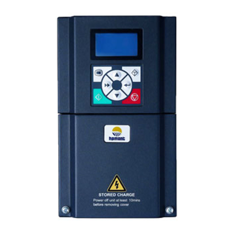
Famco MONT72 Series User manual

V1.0 2018.09
MONT72 Series
Elevator Controller
User Manual
MONT72 Series
Elevator Controller

FOREWORD
Thank you for purchasing MONT72 series elevator controller manufactured by
Shenzhen Hpmont Technology Co., Ltd.
This User Manual describes how to use MONT72 series elevator controller and their
installation wiring, parameter setting, troubleshooting and daily maintenance etc.
Before using the product, please read through this User Manual carefully. In addition,
please do not use this product until you have fully understood safety precautions.
Note:
Preserve this Manual for future use.
If you need the User Manual due to damage, loss or other reasons, please contact
the regional distributor of our company or directly contact our company Technical
Service Center.
If you still have some problems during use, please contact our company Technical
Service Center.
Due to product upgrade or specification change, and for the purpose of
improving convenience and accuracy of this manual, this manual’s contents may
be modified.
Email address: overseas_[email protected]

Version and Revision Records
Version time: 2018/9
Version: V1.0
Chapter Content
•V1.0 issue

CONTENTS
Chapter 1 Safety Information and Precautions.................................................................................................... 1
1.1 Safety Definition ............................................................................................................................... 1
1.2 About Motor and Load..................................................................................................................... 1
1.3 About MONT72 Controller .............................................................................................................. 2
1.4 Maintenance...................................................................................................................................... 3
Chapter 2 Product Information............................................................................................................................... 7
2.1 Model.................................................................................................................................................. 7
2.2 Nameplate.......................................................................................................................................... 7
2.3 Technical Data ................................................................................................................................... 8
2.4 Rated Value ...................................................................................................................................... 10
2.5 Dimension........................................................................................................................................ 11
2.6 Resistor Selection ........................................................................................................................... 11
Chapter 3 Mechanical Installation........................................................................................................................ 13
3.1 Precautions ...................................................................................................................................... 13
3.2 Installation Site Requirement ....................................................................................................... 13
3.3 Installation Direction and Space Requirements ........................................................................ 14
Chapter 4 Electrical Installation............................................................................................................................ 15
4.1 Precautions ...................................................................................................................................... 15
4.2 Peripheral Accessories Selection.................................................................................................. 15
4.2.1 Wiring Specifications of Input and Output ....................................................................................... 15
4.2.2 Power Terminal Lug................................................................................................................................... 17
4.3 Power Terminals and Wiring.......................................................................................................... 17
4.3.1 Power Terminal Description ................................................................................................................... 18
4.3.2 Power Terminal Wiring.............................................................................................................................. 19
4.4 Control Board .................................................................................................................................. 20
4.4.1 Indicators and Jumper Description .....................................................................................................20
4.4.2 Controlling Terminals Description .......................................................................................................21
4.4.3 Terminals Wiring......................................................................................................................................... 21
4.5 Encoder Card ................................................................................................................................... 23
4.5.1 Introduction................................................................................................................................................. 23
4.5.2 Wiring Requirement .................................................................................................................................. 23
4.5.3 FD Description ............................................................................................................................................ 23
4.5.4 HD-PG2-OC-FD............................................................................................................................................ 24
4.5.5 HD-PG5-SINCOS-FD................................................................................................................................... 26

4.5.6 HD-PG6-UVW-FD........................................................................................................................................ 27
4.5.7 HD5L-PG1-SC............................................................................................................错误!未定义书签。
4.6 Meet EMC Requirement of Installation ....................................................................................... 30
4.6.1 Correct EMC Installation .......................................................................................................................... 30
4.6.2 Wiring Requirement .................................................................................................................................. 31
4.6.3 Motor Connection...................................................................................................................................... 31
4.6.4 Ground Connection................................................................................................................................... 32
4.6.5 EMI Filter........................................................................................................................................................ 32
4.6.6 Conduction, Radiation, Radio Frequency Interference Countermeasures............................33
4.6.7 Reactor........................................................................................................................................................... 33
Chapter 5 Operation Instructions......................................................................................................................... 35
5.1 Function Description...................................................................................................................... 35
5.1.1 MONT72 Operation Mode....................................................................................................................... 35
5.1.2 Controller Status......................................................................................................................................... 36
5.1.3 Control Mode............................................................................................................................................... 36
5.1.4 Controller Running Mode ....................................................................................................................... 36
5.2 LCD Keypad...................................................................................................................................... 37
5.2.1 Display Description ................................................................................................................................... 37
5.2.2 Four-layer Menu Description ................................................................................................................. 39
5.2.3 Example for Keypad .................................................................................................................................. 40
5.3 Phone APP........................................................................................................................................ 43
Chapter 6 Function Introduction.......................................................................................................................... 45
6.1 Group D: Display Parameters........................................................................................................ 46
6.1.1 D00: System Status Parameters.............................................................................................................46
6.1.2 D01: Drive Status Parameters................................................................................................................. 46
6.1.3 D02: Analogue Status Display Parameters........................................................................................47
6.1.4 D03: Running Status Parameters..........................................................................................................48
6.1.5 D04: Encoder Status Parameters...........................................................................................................48
6.2 Group F: General Function Parameters....................................................................................... 49
6.2.1 F00: Basic Parameters ............................................................................................................................... 49
6.2.2 F01: Protection of Parameters ............................................................................................................... 50
6.2.3 F02: Start & Stop Parameters.................................................................................................................. 51
6.2.4 F03: Acc. / Dec. Parameters..................................................................................................................... 52
6.2.5 F04: Analogue Curve Parameters ......................................................................................................... 53
6.2.6 F05: Speed Parameters............................................................................................................................. 53
6.2.7 F06: Weighing Compensation Parameters........................................................................................55
6.2.8 F07: Asyn. Motor Parameters ................................................................................................................. 55

6.2.9 F08: Motor Vector Control Speed-loop Parameters ....................................................................... 58
6.2.10 F09: Current-loop Parameters .............................................................................................................59
6.2.11 F10: Syn. Motor Parameters ................................................................................................................. 59
6.2.12 F11: PG Parameters ................................................................................................................................. 61
6.2.13 F12: Digital I/O Terminal Parameters.................................................................................................61
6.2.14 F13: Analogue I/O Terminal Parameters ..........................................................................................64
6.2.15 F15: Display Control Parameters ........................................................................................................65
6.2.16 F16: Function-boost Parameters ........................................................................................................ 66
6.2.17 F17: Fault Protect Parameters.............................................................................................................. 67
6.2.18 F18: PWM Parameters ............................................................................................................................ 69
6.3 Y Group: Manufacturer Function Parameters ............................................................................ 70
6.4 U Group: Application Macro Parameters .................................................................................... 70
Chapter 7 Elevator Application Guidance........................................................................................................... 73
7.1 Basic Commissioning Procedures ................................................................................................ 73
7.1.1 Set Basic Parameters................................................................................................................................. 73
7.1.2 Motor Auto-tuning .................................................................................................................................... 73
7.1.3 Inspection Running................................................................................................................................... 75
7.1.4 High Speed Running................................................................................................................................. 75
7.1.5 Leveling Accuracy Adjustment.............................................................................................................. 76
7.2 Terminal MS Run Application........................................................................................................ 78
7.3 Terminal Analogue Run Application............................................................................................ 81
7.4 Application of Power Failure Emergency Operation Mode ..................................................... 83
Chapter 8 Troubleshooting and Maintenance ................................................................................................... 85
Appendix A Parameters ......................................................................................................................................... 91


Shenzhen Hpmont Technology Co., Ltd. Chapter 1 Safety Information and Precautions
MONT72 Series User Manual V1.0 - 1 -
Chapter 1 Safety Information and Precautions
1.1 Safety Definition
Danger: A Danger contains information which is critical for avoiding safety hazard.
Warning: A Warning contains information which is essential for avoiding a risk of damage to
products or other equipments.
Note: A Note contains information which helps to ensure correct operation of the product.
1.2 About Motor and Load
Compared to the industrial frequency operation
The MONT72 series controllers are voltage-type controllers and their output is PWM wave with certain
harmonic wave. Therefore, the temperature, noise and vibration of the motor will be a little higher than
that at industrial frequency running.
Thermal protection of motor
When choose the adaptive motor, MONT72 can effectively implement the motor thermal protection.
Otherwise it must adjust the motor protection parameters or other protection measures to ensure that
the motor is at a safe and reliable running.
Lubrication of mechanical devices
At long time low-speed running, provide periodical lubrication maintenance for the mechanical
devices such as gear box and geared motor etc. to make sure the drive results meet the site need.
Start and stop MONT72
User should use the control terminal to start and stop MONT72. It is strictly forbidden to use contactor
or other switches on the input side of MONT72 to start and stop directly, or it will damage the device.
Check the insulation of the motor
For the first time using the motor or after long time storage, it needs check the insulation of the motor.
Worse insulation can cause damage to MONT72.
Note:
Use a 500V Mega-Ohm-Meter to test and the insulation resistance must be higher than 5Mohm.
Requirement for leakage current protector RCD
Since the device generates high leakage current which goes through the protective grounding
conductor, please install B type leakage current protector RCD on one side of the power supply.
For the selection of RCD, users need to consider the possible problems of ground leakage current in
both transient status and steady status at start and during running. It is recommended to choose
either special RCD that can suppress the higher harmonics, or general RCD that has more aftercurrent.
Danger
Warning
Note
1

Chapter 1 Safety Information and Precautions Shenzhen Hpmont Technology Co., Ltd.
- 2 - MONT72 Series User Manual V1.0
Warning for ground mass leakage current
The device generates mass leakage current, so users need to confirm the reliable grounding before
connect to the power supply. The grounding should comply with the local relative IEC standard.
1.3 About MONT72 Controller
No capacitor or varistor on the output side
Since MONT72 output is PWM wave, it is strictly forbidden to connect capacitor for improving the
power factor or varistor for lightning protection to the output terminals so as to avoid MONT72 fault
trip or component damage.
Contactors and circuit breakers connected to the output of MONT72
If circuit breaker or contactor needs to be connected between MONT72 and the motor, be sure to
operate these circuit breakers or contactor when MONT72 has no output, so as to avoid any damage to
MONT72.
Running voltage
MONT72 is prohibited to be used beyond the specified range of running voltage. If needed, please use
the suitable voltage regulation device to change the voltage.
Capacitor energy storage
When the AC power supply is cut off, capacitor of MONT72 sustains deadly power for a while. So to
disassemble MONT72 that is powered, please cut off the AC power supply for more than 10 minutes,
confirm the internal charge indicator is off and the voltage between (+) and (-) of the main circuit
terminals is below 36V.
Generally, the internal circuit enables the capacitor to discharge. However, the discharging may fail in
some exceptions. In these cases, users need to consult Hpmont or our regional distributor.
Change three-phase input to single-phase input
For three-phase input controller, users should not change it to be single-phase input.
To use single-phase power supply, disable the input phase-loss protection function. And the
bus-voltage and current ripple will increase, which not only influences the life of electrolytic capacitor
but also deteriorates the performance of the controller. In that case, the controller must be derating
and should be 60% within rated value of controller.
Lightning surge protection
MONT72 internal design has lightning surge over-current protection circuit, and has certain
self-protection capacity against the lightning.

Shenzhen Hpmont Technology Co., Ltd. Chapter 1 Safety Information and Precautions
MONT72 Series User Manual V1.0 - 3 -
Altitude and derating
In area where altitude exceeds 1000 meters, MONT72 should be derating since the heatsink efficiency
will be reduced because of the tenuous air.
The rated value of output current derates by 1% for each 100m increase of the altitude. I.e for the
altitude of 3000m, derated rate is 20% for rated current of MONT72. Figure 1-1 is the derating curve of
rated current and the altitude.
Figure 1-1 Derating curve of rated current and altitude
1.4 Maintenance
Due to environmental temperature, humidity, pH, dust, vibration and other factors, as well as the aging
and wear of the device inside the drive controller, etc., it will lead to potential failures. Therefore, the
controller must be stored and used. Daily or regular maintenance.
•If the drive controller is transported over long distances, it should be routinely checked before use
to confirm that the product components are complete and the nails are fastened.
•During the use of the drive controller, the internal dust of the drive should be cleaned regularly.
Check the internal fastening screws to make sure there is no looseness.
•MONT72 can only be maintained by qualified and trained professionals.
•Maintenance personnel must remove the metal jewelry before maintenance. Maintenance must use clothing and
tools that meet the insulation requirements.
•The MONT72 is in a live, running, dangerous high voltage inside.
•Before checking and maintaining the MONT72, disconnect the input power reliably and wait at least 10 minutes.
Check that the MONT72 internal charge indicator is off and the voltage between the power terminals (+) and (-) is
lower than 36V. In order to open the MONT72 cover for maintenance.
•For drive controllers that have been stored for more than 2 years, the regulator should be slowly boosted by the
regulator during the first power-up.
•Do not leave metal objects such as wires, tools, and dowels inside the drive controller.
•Do not modify the drive controller without authorization.
•There are static-sensitive IC components inside the drive controller. Do not touch the on-board device directly.
70%
100%
1000m 4000m
Altitude
Rated current of MONT72
Danger
Warning
1

Chapter 1 Safety Information and Precautions Shenzhen Hpmont Technology Co., Ltd.
- 4 - MONT72 Series User Manual V1.0
Daily maintenance
The MONT72 must be operated in the specified environment, see section 3.2, page 13.
Please follow Table 1-1 to do daily maintenance work, in order to find abnormal phenomena in time
and extend the service life of MONT72.
Table 1-1 Daily inspection project
Check object Check content Judging criteria
Operating
environment
Temperature, humidit -10 - +40°C, 40 - 50°C derating required; Less than 95% RH, anhydrous
beads condensation
Dust, water and drip No conductive dust accumulation, no trace of water leakage
Gas No smell
Drive controller Vibration, heat Stable vibration, reasonable temperature
Noise No noise
Motor Over-heat No abnormality
Noise Normal noise
Status
parameters
Output current /
current Current in the rated range
Regular maintenance
Depending on the usage environment, the user can perform regular routine inspections of the drive
controller within 3-6 months to eliminate potential hazards and ensure long-term high performance
and stable operation of the equipment.
The inspection contents are as follows:
•The control terminal is not loosened. If it is loose, it can be tightened with a suitable torque;
•The power terminals are in firm contact and there are no signs of overheating at the copper bars or
cable connections;
•Power cable, control cable for damage, especially for the skin that is in contact with the metal
surface;
•The wire nose insulation wrap of the power cable and control signal wire does not fall off or rupture;
•For dust cleaning on the circuit board and on the air duct, it is best to use a vacuum cleaner.
Note:
1. The drive controller has passed the pressure test before leaving the factory. The user does not need to
carry out the test. Otherwise, it will be damaged if the test is improper.
2. If the insulation test is performed on motor, the U / V / W terminal of the drive controller must be
disconnected and the motor tested separately, otherwise the drive controller will be damaged.
3. The long-term storaged drive controller must conduct a power-on experiment within 2 years. Use the
voltage regulator to slowly increase the input voltage of the driver to the rated value, and energize for at
least 5 hours.

Shenzhen Hpmont Technology Co., Ltd. Chapter 1 Safety Information and Precautions
MONT72 Series User Manual V1.0 - 5 -
Drive controller consumable replacement
Drive controller consumables mainly include cooling fans and filter electrolytic capacitors. Their service
life is closely related to the environment and maintenance conditions. Users can set the replacement
period according to the running time.
Consumables Cooling fan Filter electrolytic capacitor
Life time 60,000 hours 50,000 hours
Possible causes of
damage Bearing wear, blade aging
Ambient temperature is high, frequent load
jumps cause pulsating current to increase,
electrolyte aging
Discrimination
standard
When the drive controller is powered off,
check whether there are cracks in the fan
blades, etc. When the drive controller is
energized, check whether the fan is running
normally, whether there is abnormal
vibration, noise, etc.
Is the drive controller often overcurrent
when it is running with load? Overvoltage
and other faults; Whether there is liquid
leakage, whether the safety valve has
protruded, determination of electrostatic
capacitance, determination of insulation
resistance
Scrap treatment
When scrapping, please note:
•An electrolytic capacitor inside the drive controller may cause an explosion when it is incinerated.
•Toxic gases are produced when plastic parts are incinerated.
•Please treat as industrial waste.
1


Shenzhen Hpmont Technology Co., Ltd. Chapter 2 Product Information
MONT72 Series User Manual V1.0 - 7 -
Chapter 2 Product Information
2.1 Model
2.2 Nameplate
MT72-4T015
Product series
Motor power
200 - 240V = 2
380 - 460V = 4
Elevator dedicated controller
Phases
Single phase power inpu
t = S
Single / three phases compatible power input = D
Three phases power input = T
Voltage
Product model
Motor
Input date
Output date
Software version
Bar code
MODEL: MT72-4T5P5
5.5kW
POWER:
3PH 380-460V 15A 50/60Hz
INPUT:
8.5kVA 0-460V 13A 0-100Hz
OUTPUT:
1.00
Version:
2

Chapter 2 Product Information Shenzhen Hpmont Technology Co., Ltd.
- 8 - MONT72 Series User Manual V1.0
2.3 Technical Data
Electrical specifications
Input voltage
Single / three phase: 200 - 240V
Three phase: 380 - 460V
Fluctuation does not exceed ± 10%, imbalance rate < 3%
Input frequency 50/60Hz ± 5%
The output voltage 0 - Input voltage
Output frequency 0 - 100.00Hz
Performance
Overload capability 150% rated output current for 2 minutes
180% rated output current 10 seconds
Control method V/f control; Open loop vector control (SVC); Closed loop vector control (VC)
Run command setting
mode Keypad setting, external terminal setting
Speed setting method Digital setting, analog setting
Speed setting resolution Digital setting: 0.01Hz
Analog setting: 0.1% × maximum frequency
Speed control accuracy SVC: ± 0.5% VC: ± 0.05%
Speed control range SVC: 1:100 VC: 1:1000
Torque control response SVC: < 200ms VC: < 50ms
Starting torque SVC: 180% rated torque / 0.5Hz VC: 180% rated torque / 0Hz
Torque control accuracy ± 5%
Special feature
Multiple sets of parameters
upload and download
function
2 sets of parameters can be uploaded to the keypad backup function
Programmable input and
output interface Input terminal function can be edited, output terminal function can be edited
Protective function
Power-on safety self-test Power-on peripherals security checks, eliminate safety hazards
Overspeed protection Elevator overspeed protection features to ensure safe operation
Speed deviation protection Has a speed deviation detection protection, eliminate safety hazards
Up and down forced speed
change function
With up and down forced speed change function, preventing the elevator from
slamming the bottom
Input, output phase loss
protection Input, output phase loss automatic detection and alarm function
Traction machine
temperature detection Real-time detection of motor temperature to eliminate safety hazards
Output short circuit
protection Output to ground short-circuit effective protection
Output phase-to-phase
short circuit protection Output phase-to-phase short circuit effective protection

Shenzhen Hpmont Technology Co., Ltd. Chapter 2 Product Information
MONT72 Series User Manual V1.0 - 9 -
Input output
External analog power
supply +10V, load capacity 100mA
External power input External 24VDC power input
Analog input AI1: Voltage 0 - 10V
Digital input X1 - X10
Digital output DO1, DO2
Relay output Y1 - Y3, contact capacity: 250VAC/3A or 30VDC/3A
RA / RB / RC, contact capacity: 250VAC/5A or 30VDC/5A
Keypad display
LCD display Function parameter setting, status parameter viewing, fault code viewing, etc.
Parameter copy Fast parameter copying
Environmental characteristics
Working temperature -10 - +40°C, up to 50°C, air temperature change is less than 0.5°C/min
Derating at 40 - 50°C: 2% reduction in output current per 1°C
Storage ambient
temperature -40 - +70°C
Place of use Indoor, free from direct sunlight, no dust, corrosive gases, flammable gases, oil mist,
water vapor, dripping or salt, etc.
Altitude Less than 1000 meters, more than 1000 meters need to be derated
Humidity Less than 95% RH, anhydrous beads condensation
Vibration resistant 2 - 9Hz when 3.5m/s2, 9 - 200Hz when 10m/s2(IEC60721-3-3)
Protection level IP00
Pollution level Level 2 (Dry, non-conductive dust pollution)
Optional accessories
Encoder card
Frequency division output OC encoder card (HD-PG2-OC-FD)
Frequency division output sine and cosine encoder card (HD-PG5-SINCOS-FD)
Long-line drive encoder card with crossover output (HD-PG6-UVW-FD)
Serial communication encoder card with crossover output (HD5L-PG1-SC) (supports
the EnDat protocol)
Keypad MT70-LED-D
Bluetooth module MT70-BLE-A
Power unit Energy feedback unit (HDRU)
2

Chapter 2 Product Information Shenzhen Hpmont Technology Co., Ltd.
- 10 - MONT72 Series User Manual V1.0
2.4 Rated Value
Structure Model Motor
(kW)
Rated capacity
(kVA)
Rated input
current (A)
Rated output
current (A)
Single-phase: 200 - 240V, 50/60Hz
FA MT72-2S2P2 2.2 3.8 24.1 10.3
FA MT72-2S3P7 3.7 5.9 40 17
Single-phase / Three-phase: 200 - 240V, 50/60Hz
FB MT72-2D5P5 5.5 8.5 60 / 29 (1) 27
FB MT72-2D7P5 7.5 11 75 / 35 (1) 33
FD MT72-2D011 11 16 100 / 47 (1) 45
FD MT72-2D015 15 21 130 / 62 (1) 55
FD MT72-2D018 18.5 24 160 / 77 (1) 70
(1): Value before / is for single-phase model, value after / is for three-phase model.
Three-phase: 200 - 240V, 50/60Hz
FA MT72-2T3P7 3.7 5.9 19 17
FB MT72-2T5P5 5.5 8.5 29 27
FB MT72-2T7P5 7.5 11 35 33
FD MT72-2T011 11 16 47 45
FD MT72-2T015 15 21 62 55
FD MT72-2T018 18.5 24 77 70
FE MT72-2T022 22 30 92 80
FE MT72-2T030 30 39 113 110
Three-phase: 380 - 460V, 50/60Hz
FA MT72-4T2P2 2.2 3.4 7.3 5.1
FA MT72-4T3P7 3.7 5.9 11.9 9
FA MT72-4T5P5 5.5 8.5 15 13
FB MT72-4T7P5 7.5 11 20 18
FB MT72-4T011 11 16 29 27
FB MT72-4T015 15 21 35 33
FC MT72-4T018 18.5 24 41 39
FC MT72-4T022 22 30 50 48
FD
FF
MT72-4T030
MT72-4T030-SM 30 39 62 60
FD
FF
MT72-4T037
MT72-4T037-SM 37 49 77 75
FE MT72-4T045 45 59 93 91
FE MT72-4T055 55 72 113 112

Shenzhen Hpmont Technology Co., Ltd. Chapter 2 Product Information
MONT72 Series User Manual V1.0 - 11 -
2.5 Dimension
See Table 2-1 for the appearance and installation dimensions of MONT72. For the specific model
corresponding to the external dimensions, see section 2.4 Rated Value, page10.
FA / FB / FC / FD / FE / FF
Table 2-1 MONT72 dimension
Structure
Dimension (mm) Size (mm) Gross wet.
(kg)
W H W1 H1 D d
FA 200 350 150 344.5 159 6.5 8.7
FB 220 350 150 334.5 186 6.5 9.1
FC 220 375 195 360 199 7 13
FD 290 555 235 541.5 218 6.5 17.7
FE 380 598.5 260 576 282 10 46.6
FF 260 440 230 420 403 8 20.8
2.6 Resistor Selection
The braking resistor selection is shown in Table 2-2. For the braking resistor wiring, see section 4.3.2
Power Terminal Wiring.
Table 2-2 Brake resistor selection recommendation table
Model Motor
(kW)
Brake resistor (Ω) Brake resistor power (kW)
Min. Max. Recommendation Syn. Asyn.
Single phase: 200 - 240V, 50/60Hz
MT72-2S2P2 2.2 26 130 50 1 1
MT72-2S3P7 3.7 26 90 30 1.6 1.2
Single / Three phases: 200 - 240V, 50/60Hz
MT72-2D5P5 5.5 17 27 20 2 1.6
MT72-2D7P5 7.5 11 20 15 3.2 2
MT72-2D011 11 11 20 15 4 3.2
MT72-2D015 15 10 16 12 5 4
MT72-2D018 18.5 10 16 12 6.4 5
D
H
H1
4-Ød
W
W1
2
Table of contents
Other Famco Controllers manuals
Popular Controllers manuals by other brands

SOMFY
SOMFY animeo IB+ 1860209 installation guide

Magnetek
Magnetek SBN Series instruction manual

IMC
IMC EAGLE 2 SOLR-2ELC-10 Service and parts manual supplement

RTI
RTI MRP-64 Installation and operation guide

Wesa
Wesa DW Installation and operation manual

Norac
Norac UC4+ SPRA-COUPE 7000 Series installation manual

Swytch
Swytch Twist manual

AUSTART
AUSTART 2 Series Installation and maintenance manual

Autonics
Autonics 1-Axis High Speed Stand-Alone Series user manual

Granville-Phillips
Granville-Phillips Series 330 instruction manual

AlfaRadio
AlfaRadio AlfaSpid RAK instruction manual

Johnson Controls
Johnson Controls G76 Series Installation Sheets Manual