Famco Emaux T450 User manual

VOLUMETRIC FILTER
MODELS
T450
T500
T600
T700
T600B
T700B

2
IMPORTANT SAFETY INSTRUCTIONS
Read and follow all instructions in this owner’s manual and on the equipment. Failure to follow
instructions can cause severe injury and/or death.
Never operate or test the circulation system at more than 4 bar.
Never change the filter control valve position while the pump is running.
Hazardous Pressure. Due to the high operation pressure, some components from the pump or
the filter could be violently separated.
Do not operate the pool equipment if a system component is not assembled properly, damaged,
or missing.
1. MAIN FEATURES
Our Volumetric filter (Fig.1) is a one-piece blow moulded filter made in high density
polyethylene material manufactured to maximize the strength of the filter.
Product dimensions:
1.1. TECHNICAL FEATURES
Code
Model
No.
Filtration
area (m2)
Valve
connections
Max. working
pressure (bar)
Max. Flow
rate (m3/h)
Sand
(kg)
88016003
T450
0.16
1.5" / 50 mm
4 bar
8
75
88016004
T500
0.2
10
95
88016046
T600
0.29
14.6
165
88016007
T700
0.39
19.5
200
88016047
T600B
0.29
2" / 63 mm
14.6
165
88016008
T700B
0.39
19.5
200
Model
A
(mm)
B
(mm)
C
(mm)
T450
954
457
353
T500
1040
508
400
T600
1090
610
457
T700
1180
711
516
T600B
1142
610
457
T700B
1232
711
516
Fig 1. Volumetric filter
A
B
C

3
1.2. DOUBLE LAYERED FILTER
Due to the double-layered lateral arms (Fig. 2) and higher
filtration bed in comparison to standard sand filters, filtered
water quality is better and less frequency of backwash is
required under the same conditions.
1.3. SPECIAL DRAIN CONNECTION
Its special design allows to remove water and also
filtration medium from inside of the filter through the
connection drain (Fig. 3).
By removing the drain lid, only water will come out of
the filter. Unscrew the plastic filter with the cap of the lid
for removing filtration medium (Fig. 4).
1.4. MULTIPORT VALVE
The filters incorporate a 6-ways multiport valve (Fig. 5) which covers all the necessary
operations related with the filtration procedure: filtration, backwash, rinse, waste, recirculate
and close (Fig. 6)
Fig 2. Double layered lateral arms
Fig 3. Filter drain
Fig 4. Filter drain components
Fig 5. Multiport valve
Fig 6. Handle with all the possible positions

4
2. INSTALLATION
It is recommended to install the filter as close as possible to the swimming pool and preferably
below the surface of the water in the swimming pool and in such a way that the base lies
completely stable upon a totally horizontal surface.
The place where the filter is installed should have enough ventilation and adequate drains so
that, in case of an accident, the water can escape through the drain system, avoiding risk of
damaging the installations.
Install the filter in a place with space enough to carry out the operation and maintenance
services.
Filtration medium should be loaded once the filter is installed into its exact location, following
the instructions in the Chapter 2.2 “FILTRATION MEDIUM LOAD”.
2.1. ASSEMBLY
To assemble the filter, proceed as follows:
1. Some lateral arms could be not completely threaded. Check all the connections and thread
them if necessary.
2. Install the O-ring supplied in the plastic bag together with this manual, between the
multiport valve and the filter.
3. Turn the valve and place it to match the connections properly.
4. Tighten the clamp of the valve to the filter with the Star-Shaped Nut.
5. Assemble the three connections of the selector valve. Each of these three outlets is clearly
identified on the valve as follows.
“PUMP”: This pipe connection comes from filtration pump.
“WASTE”: This pipe connection goes to waste.
“RETURN”: This pipe connection goes back to pool.
6. Assemble the manometer and the sight glass. Install their respective O-rings.
2.2. FILTRATION MEDIUM LOAD
In order to obtain maximum efficiency from your filter, it should be filled with filtration medium
with a granulometry 0,5 –0,8 mm.
The total amount of silica sand is indicated on the specifications label of the filter, as well as in
this User Manual (see Chapter 1 “MAIN FEATURES”).
For loading the filter with filtration medium, proceed as follows:
1. Load up the filter with silica filtration medium when it is already installed in its final position.
2. Take off the multiport valve lid and the joint.
3. Install the protector lid supplied in the plastic bag together with this manual. The protector
lid matches perfectly with the neck of the filter and protects the central pipe of the filter form
filtration medium.
4. Fill the filter with water to a half of the tank height.
5. Slowly pour the required quantity of filtration medium inside the filter.
6. Remove the protector lid and install the multiport valve connecting it with the central pipe
of the filter.
7. Tighten the clamp of the valve to the filter with the Star-Shaped Nut.

5
3. OPERATION PROCESS
The multiport valve with a handle of 6 positions covers all the necessary operations to obtain
the maximum efficiency of the filter.
IMPORTANT: Before changing the position of the multiport valve handle, always switch off the
pump.
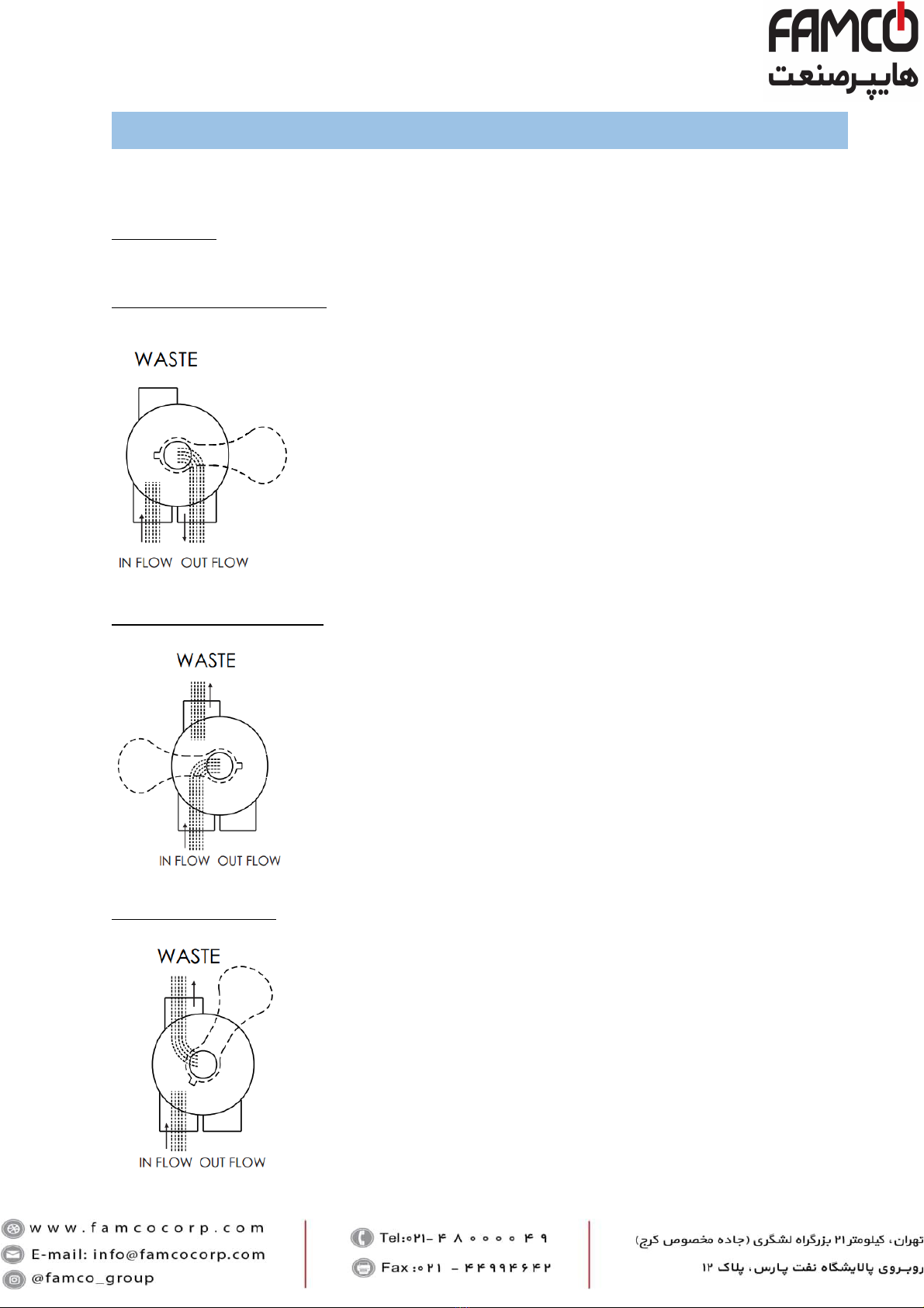
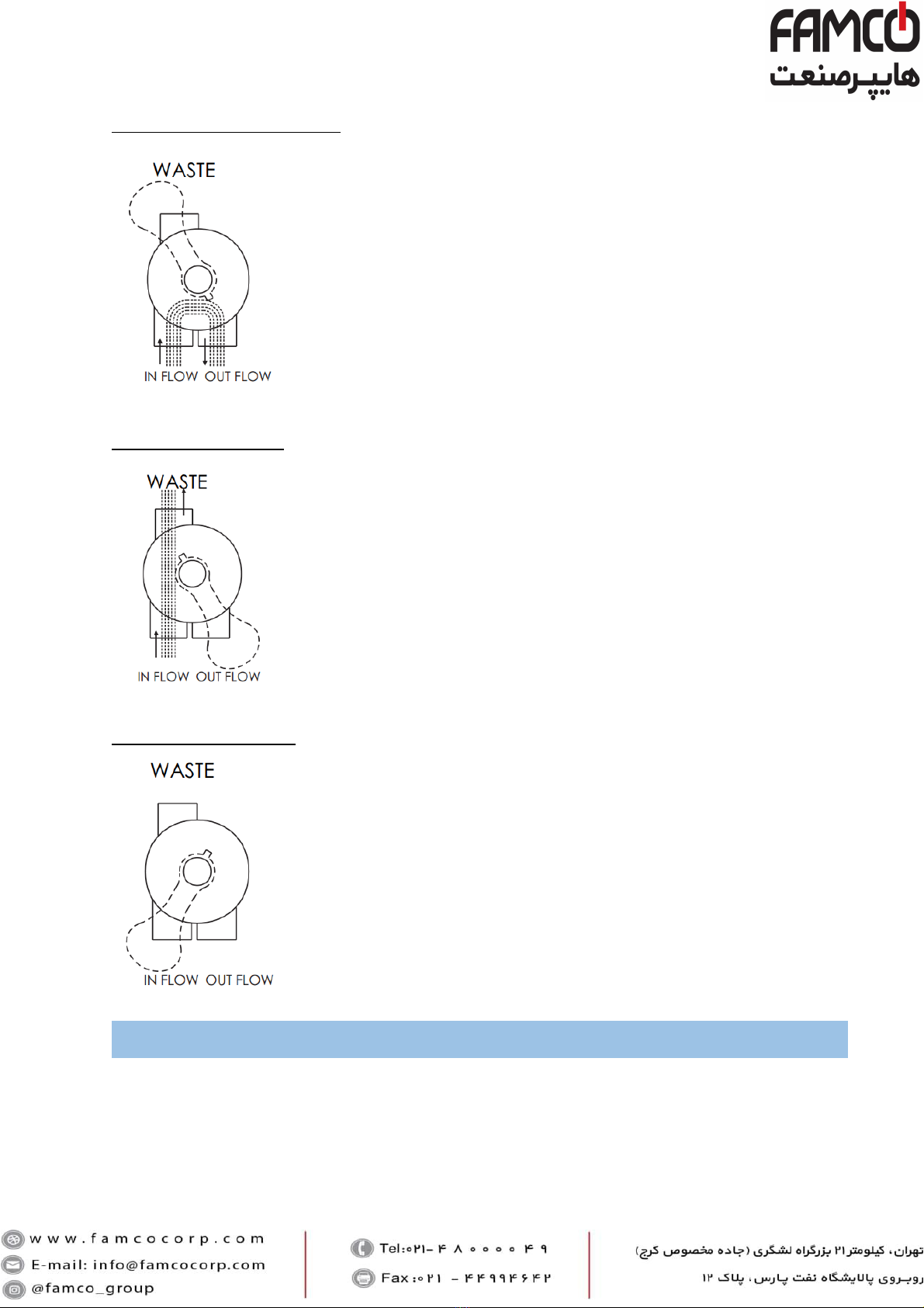
POSITION 1: FILTRATION
Switch off your filtration pump and place the handle of the multiport
valve in the “Filtration” position. Switch on the pump.
During filtration, it is recommended to control the pressure on valve’s
pressure gauge. Filtration medium forms thousands of channels while
the water is descending through the filter, and retains the suspended
solids. Gradually the number of suspended solids retained in filtration
medium increases and block the channels, getting more difficult for
water to pass through. This is why the pressure raises up inside the
filter. When the pressure reaches 3.5 bars (50 psi), the filter is
saturated and backwash is required.
POSITION 2: BACKWASH
At high pressure the filtration medium is unable to withhold impurities
and must be washed as follows:
1. Switch off your filtration pump.
2. Turn the multiport valve handle to the “BACKWASH” position.
3. Switch on the pump and run it for around 2 minutes. The quality
of the water wasted can be checked in the sight glass placed in
the waste connection of the multiport valve.
4. When this operation is completed, the dirt blocking the filter will
have been removed.
POSITION 3: RINSE
After the carrying out the backwash operation on the filter, the water
will be cloudy for a few seconds. Rinse prevents this water coming to
the pool.
Rinse is recommended immediately after the backwash for 1 minute.

6
POSITION 5: WASTE
If the swimming pool needs to be drained, the multiport valve must
be in this position.
When draining, the main drain valve is fully open, for the pump to
have sufficient suction. On the other hand, the skimmer valves and
the bottom cleaner valves must be closed in order to avoid air
suction.
POSITION 6:CLOSED
This position is for closing off the water from the filter to the pump
and it is used when opening the pump strainer or for installation
maintenance.
4. START-UP
When the filter has been loaded with filtration media, it must be washed for 4 minutes.
Proceed with the backwash as mentioned (see Chapter 3 “OPERATION PROCESS”).
When this has been done, the filter will be ready to operate.
IMPORTANT: The pump should be switched off when changing the position of the multiport
valve.
POSITION 4: RECIRCULATE
In this position, the multiport valve allows the water from the pump
to go directly to the swimming pool without passing through the
inside of the filter.

7
5. MAINTENANCE
Always replace the joints and pieces that may not be in good condition.
Backwash and rinse when is required according to the pressure gauge indications.
It’s recommended to change filtration medium regularly; in case of sand, every 3 years.
6. WINTERIZING
Before stop operating your filtration system for a long period of time, proceed with a backwash
and a rinse as previously detailed.
Remove all water from the filter by using the drain connection.
Take off the multiport valve to ventilate the filter in a period of inactivity.
When you need to start up the filter again after a period of inactivity, follow the instructions
detailed in "START UP".
7. WARRANTY POLICY
Emaux manufactures its products with the highest standard of workmanship, using the best
materials available through state of the art process.
Emaux proudly warrants its products as follows:
EXTENDED WARRANTY FOR SPECIFIC PRODUCTS
(OFFERED FROM DATE OF INVOICE)
Product
Warranty Period
Filters & Filter Systems
2 years
Pumps
1 year
Underwater Lights
1 year (bulbs 90 days)
Ladders
1 year
Control devices
1 year
Heat Pumps & Heat Exchangers
1 year
Salt Chlorinators & UV Systems
1 year (2 years for cell material)
Pool Fittings
1 year
Cleaning Equipment & All others
1 year
7.1. EXCEPTIONS THAT MAY RESULTIN DENIAL OF A WARRANTY CLAIM
1. Damage caused by careless handling, improper repackaging or shipping.
2. Damage due to misapplication, misuse, abuse or failure to operate and install the
equipment as specified in this manual.
3. Damage caused by a misuse, abuse or failure to operate and install the equipment out of
the scope of a professional level demanded in similar equipment or installation type.
4. Damage due to unauthorized product modifications or failure to use Emaux original
replacement parts.
5. Damaged caused by negligence or failure to properly maintain products as specified in this
manual.

6. Damage caused by failure to maintain water chemistry in conformity with the standards of
the swimming pool industry for any length of time.
7. Damage caused by water freezing inside the product.
8. Accident damage, fire or other circumstances outside the control of Emaux.
9. Items had been repaired or altered in any way by any person that is not authorized by
Emaux.
10.Wear & tear parts.
7.2. CLAIM PROCESS:
Summary of Emaux Claim Process in 3 steps:
1. Claim: Customer contacts Emaux salesperson and provides completed details of the claim
which includes:
a) Information about the failed product such as the part number(s) and serial number(s).
b) Description of the complaint/failure.
c) Pictures
2. Once the complaint is received, the product quality incident will then be reviewed by Emaux’
Quality Department following the “Emaux Warranty Policy”.
3. Conclusion: After the investigation is completed, Emaux will inform the distributor
accordingly.
7.3. WARRANTY OBLIGATION
Should a defect become evident during the term of warranty, Emaux will, at its option, repair
or replace such item or part at its own cost and expense. Customer will need to follow the
warranty claim procedures from Emaux in order to obtain the benefit on this warranty.
Emaux is not, however, responsible under this warranty for any cost of shipping or transportation
of the equipment or parts thereof “to” or “from” our technical operations. Emaux is not able to
liable for any loss of time, inconvenience, incidental expenses such as labor cost, phone calls,
legal cost or material cost incurred in connection with the replacement or removal of the
equipment, or any other consequential or incidental damage on persons or assets. Emaux will
be not responsible for any business profit loss operation stop due to the non-conformity product
equipment. No indemnity or damages can be claimed on any account whatever.
7.4. WARRANTY OR REPRESENTATIONS BY OTHERS
No dealer or other person has authority to make any warranty or representation concerning
Emaux or its products.
Accordingly, Emaux is not responsible for any such warranty or representation.
8
This manual suits for next models
5
Table of contents