Fantini Cosmi CH176D User manual
CH176D
INSTRUCTIONS FOR USE
FANTINI COSMI S.p.A.
Via dell’Osio, 6 20090 Caleppio di Settala, Milan – ITALY
Tel. +39 02 956821 | Fax +39 02 95307006 | info@fantinicosmi.it
www.fantinicosmi.it
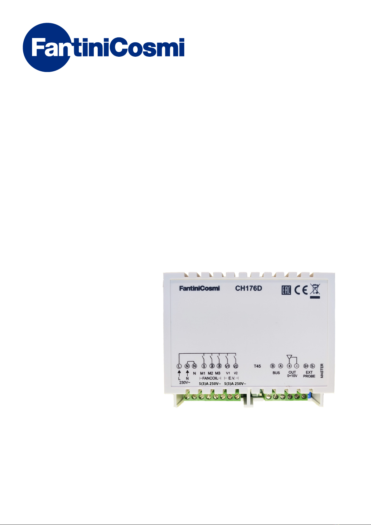
DIN RAIL WIRED ACTUATOR FOR
FAN COIL ROOM THERMOSTAT

2
DIN RAIL WIRED ACTUATOR FOR FAN COIL ROOM THERMOSTAT
CH176D
Thank you for purchasing a FANTINI COSMI S.p.A. product
Please read this instruction manual carefully and always keep it at hand should you need to consult it for any reason.
The documentation reflects the characteristics of the product. However, for regulatory or commercial developments,
customers should verify the availability of updates relating to this documentation on the FANTINI COSMI S.p.A.
website: pdf.fantinicosmi.it
OPERATION
The CH176D unit is an actuation model which, connected to a thermostat for fan coil CH133AR2 - CH133RR - CH130AR2
- CH130ARR - CH130RR via a bipolar cable, allows to remotely control the two valves, the three-speed motor or a 0 .. 10V,
motor, and accept a temperature sensor connected to the appropriate input.
The bipolar cable connecting the module to the thermostat, has a dual function:
■powering the fan coil thermostat,
■communication bus between thermostat and actuation module.
The CH176D unit is compatible with the CH172D actuator via external set-up. It is possible to connect a single thermostat
to several actuators, so as to control more than one fan coil simultaneously with only two cables; for this application,
carefully follow the detailed instructions in the document.
CONTENTS OF PACKAGE
■1 actuator
■1 user manual

3
DIN RAIL WIRED ACTUATOR FOR FAN COIL ROOM THERMOSTAT
CH176D
TECHNICAL FEATURES
Power supply and absorbed power 230Vac 50Hz - 2VA
BUS A/B input Power supply + thermostat data (default setting: SLAVE)
Relay output features 5(3)A 250V~
Voltage-free switching contacts with mains voltage 2 valve outputs (N-V1 and N-V2)
Mains voltage switching contacts 3 motor contact outputs (M1, M2 and M3)
0 ... 10V output 20 mA - 470Ω
Probe input NTC 10 KΩ (Fantini EC15-EC18-EC19-EC20)
Protection rating IP00
Software class A
Maximum temperature T45
Degree of pollution 2
Complies with Standards EN60730-1 and second parts
Micro-disconnection 1B
Impulse voltage 4000V
Assembly type and dimensions 6-module DIN Rail
Product not made in Italy

4
DIN RAIL WIRED ACTUATOR FOR FAN COIL ROOM THERMOSTAT
CH176D
CONTENTS
OPERATION ..................................................................... 2
CONTENTS OF PACKAGE................................................. 2
TECHNICAL FEATURES ................................................... 3
1 - INSTALLATION ........................................................... 5
2 - CONNECTING SEVERAL MODULES TO ONE
THERMOSTAT .................................................................. 6
3 - OPERATING MODE SELECTION (COMPATIBILITY WITH
ACTUATOR CH172D) ...................................................................6
4 - LUMINOUS STATUS INDICATOR (LED) ....................... 7
5 - COMMISSIONING AND OPERATIONAL CHECK........... 7
DISPOSAL........................................................................ 7
GENERAL WARRANTY CONDITIONS ............................... 7
Solenoid valves
230Vca
external probe input
0 ÷ 10V output
BUS
BUS
5(3)A 250V~
5(3)A 250V~
5(3)A 250V~
5(3)A 250V~ 5(3)A 250V~
5
DIN RAIL WIRED ACTUATOR FOR FAN COIL ROOM THERMOSTAT
CH176D
1 - INSTALLATION
The device is designed for installation on DIN rail, but its small size facilitate the installation inside the fan coil also.
ATTENTION!
The end parts (live) of the CH176D must be installed in a container or fan coil inaccessible by the user.
Installation must be carried out by qualified personnel, in compliance with the requirements concerning
installation of electrical devices. Make sure that the power network is disconnected before making any
connections or working on the device.
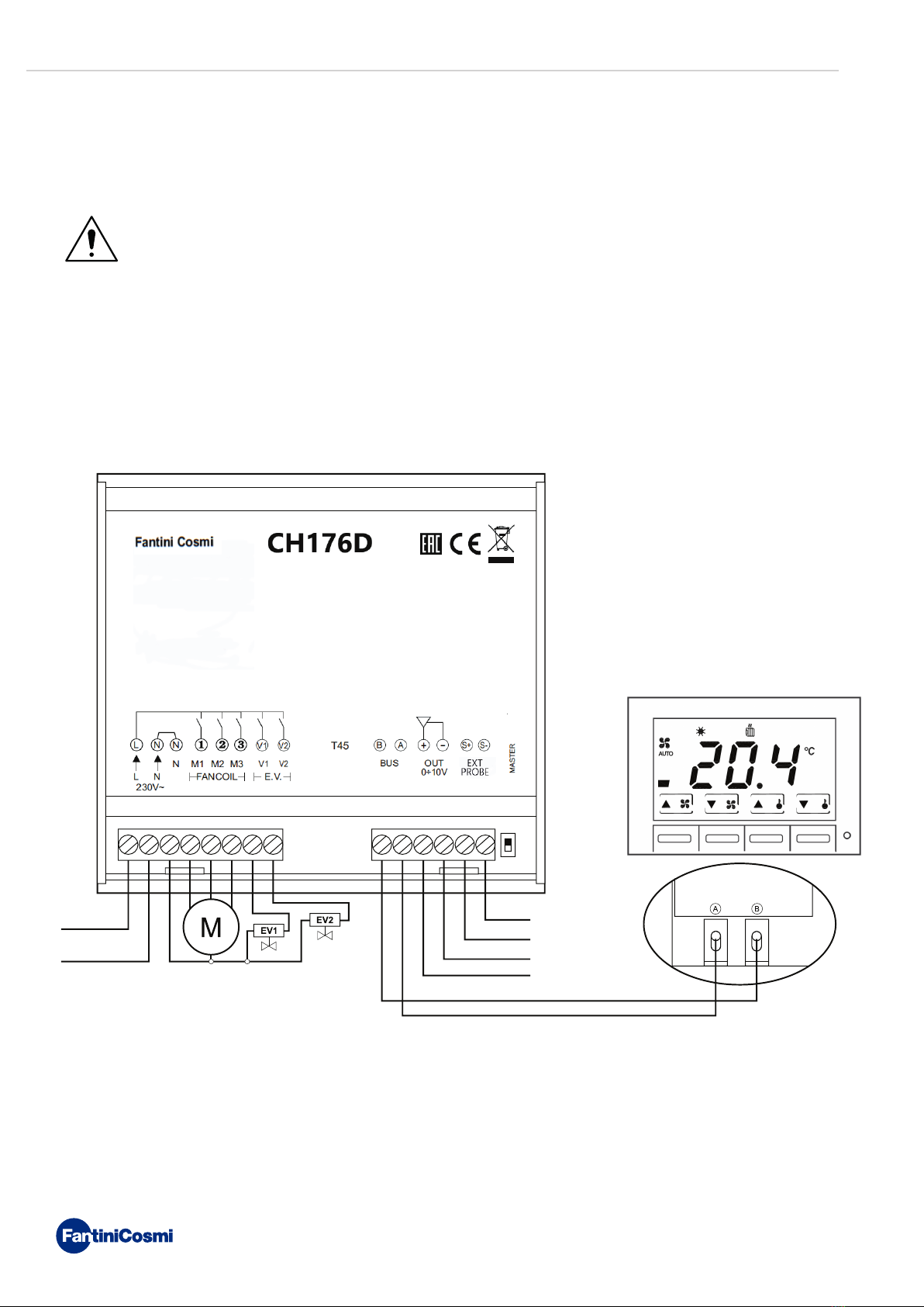
The following figure shows the circuit diagram of the connections.
The distance between the actuator module and thermostat must not exceed 100 metres.
In air conditioning systems with four pipes, valve 1 (terminals N and V1) controls the heating circuit while valve 2 (terminals
N and V2) controls the cooling circuit.
The temperature sensor (NTC 10KΩ) must be connected to the PROBE input. The 0 ... 10V motor must be connected to
the specific 0-10V OUT output, respecting its polarities.

BUS
BUS
BUS
*
#
6
DIN RAIL WIRED ACTUATOR FOR FAN COIL ROOM THERMOSTAT
CH176D
2 - CONNECTING SEVERAL MODULES TO ONE THERMOSTAT
A CH133AR2 - CH133RR - CH130AR2 - CH130ARR - CH130RR thermostat can control up to five fan-coils simultaneously,
using only two wires to connect to the various actuation modules. In this case, only one of the two CH176D modules
must have the “BUS selector” in “MASTER” position, while all others must be left in “SLAVE” mode (default setting). The
temperature probe connected to the actuation module set up as “MASTER” is the one read by the thermostat.
The connection between the various devices must be made as per the diagram in the following figure.
3 - OPERATING MODE SELECTION (COMPATIBILITY WITH ACTUATOR CH172D)
If thermostats CH133RR - CH130RR - CH130ARR are connected to the actuation module, it must be configured in CH172D
mode. The selection is made by switching on the actuation module by means of the configuration of the probe input
according to the following diagram:
CH176D: probe input free or connected to a temperature probe
CH172D: temperature probe input permanently short-circuited by means of a conductor cable
BUS selector in ON position (MASTER)
Note:
BUS selector in OFF position (SLAVE)

7
DIN RAIL WIRED ACTUATOR FOR FAN COIL ROOM THERMOSTAT
CH176D
DISPOSAL
The symbol of the crossed-out wheeled bin indicates that the products must be collected and disposed of
separately from household waste. The batteries and integrated accumulators may be disposed of together
with the product. They will be separated at the recycling facilities. A black bar indicates that the product was
placed on the market after 13 August 2005. Participating in the separate collection of products and batteries
contributes to the correct disposal of these materials and therefore avoids possible negative consequences
for the environment and human health. For more detailed information on the collection and recycling programmes
available in your country, contact the local authorities or the sales point where you purchased the product.
GENERAL WARRANTY CONDITIONS
The conventional warranty lasts 24 months, starting from the date the equipment is installed. The warranty covers all
parts of the equipment, with the exception of those subjected to normal wear through use.
4 - LUMINOUS STATUS INDICATOR (LED)
The CH176D unit is equipped with a status indicator made via a two-coloured LED diode.
Flashing red: the actuation module is configured as Master and is receiving a command from the
thermostat.
Flashing green: the actuation module is configured as Slave and is receiving a command from the
thermostat.
Flashing red and green
alternately: protection. After twenty minutes during which the actuation module does not receive
commands from the thermostat, the relays are deactivated and the 0 ... 10V output is
brought to 0V. Upon reception of a command, the actuation module resumes normal
operation.
5 - COMMISSIONING AND OPERATIONAL CHECK
Commissioning and testing procedure:
■make sure that the actuator is properly connected to the thermostat;
■set the “BUS selector” to ON (MASTER);
■set up the actuation module as CH176D or CH172D (according to the thermostat connected to it);
■supply 230Vac power to the actuator;
■check that the thermostat is turned on;
■by consulting the manual of the thermostat, set it in the different operating modes (winter and summer) with
consistent set-points and gradually select the various ventilation speeds (1, 2 and 3), check switching of the various
relay and the subsequent actuations of the V1/V2 valves and the fan coil motor.

FANTINI COSMI S.p.A.
Via dell’Osio, 6 20090 Caleppio di Settala, Milan – ITALY
Tel. +39 02 956821 | Fax +39 02 95307006 | info@fantinicosmi.it
www.fantinicosmi.it
5679956 + 01/2021
Table of contents
Other Fantini Cosmi Controllers manuals


Popular Controllers manuals by other brands

Digiplex
Digiplex DGP-848 Programming guide

YASKAWA
YASKAWA SGM series user manual

Sinope
Sinope Calypso RM3500ZB installation guide

Isimet
Isimet DLA Series Style 2 Installation, Operations, Start-up and Maintenance Instructions

LSIS
LSIS sv-ip5a user manual

Rockwell Automation
Rockwell Automation 1769-L31 installation instructions


