Fapim OLTRE User manual
Life in evolution
OLTRE
Art. 8590A Art. 8590B
ELETTROMANIGLIA
ELECTRIC HANDLE
ELECTRO-POIGNEE
ELECTRO MANILLA
ЭЛЕКТРОМЕХАНИЧЕСКИЙ ЗАМОК
IT
EN
FR
ES
RUS
1
13
25
37
49
UGQU Rev.02
Life in evolution
IT
1
8590A 8590B OLTRE
1. CARATTERISTICHE TECNICHE 2
2. INSTALLAZIONE 3
3. FUNZIONAMENTO 6
4. REGOLAZIONE DELLA TEMPORIZZAZIONE 6
4.1 Regolazione della temporizzazione a 0 secondi 6
4.2 Regolazione della temporizzazione da 5 a 60 secondi 6
5. FERMO A GIORNO ELETTRICO 7
6. ABILITAZIONE E DISABILITAZIONE DEI LED BIANCO/BLU
DI ILLUMINAZIONE INFERIORE 7
6.1 Disabilitazione del led bianco/blu 7
6.2 Abilitazione del led bianco/blu 7
7. SOSTITUZIONE DEL CILINDRO 8
8. ESEMPI DI INSTALLAZIONE 9
8.1 Elettromaniglia con Oltre Bar e Pad 9
8.2 Elettromaniglia con Oltre Push 9
9. SCHEMA DI COLLEGAMENTO 10
9.1 Alimentazione in “DC” con attivazione diretta di corrente
Portare la temporizzazione a 0 secondi 10
9.2 Alimentazione in “AC” con attivazione diretta di corrente
Portare la temporizzazione a 0 secondi 10
9.3 Alimentazione in “DC” e apertura con contatto 11
9.4 Alimentazione in “AC” e apertura con contatto 11
9.5 Collegamento Elettromaniglia su impianto citofono12

Utilizzabile per uso esterno. Si raccomanda una protezione da pioggia diretta.
IT
Life in evolution 2
8590A 8590BOLTRE
1. CARATTERISTICHE TECNICHE
Art. 8590A Art. 8590B
STATO IN ASSENZA
DI CORRENTE
Maniglia
Disabilitata
MANO Ambidestra
9mm
ALIMENTAZIONE 12 / 24 Vdc
12 Vac
CORRENTE DI SPUNTO
(I max) 700 mA
CORRENTE DI
MANTENIMENTO
(I max)
TEMPORIZZAZIONE Regolabile
da 0 - 60 secondi
SEGNALAZIONE
ESTERNA
(OPEN COLLECTOR)
ILLUMINAZIONE
INFERIORE
BIANCA / BLU
FERMO A GIORNO Meccanico
e Elettrico
Maniglia
Disabilitata
Ambidestra
QUADRO MANIGLIA 9mm
700 mA
500 mA 500 mA
Regolabile
da 0 - 60 secondi
Si Si
Si Si
Meccanico
e Elettrico
CILINDRO Si No
L'elettromaniglia è predisposta all'abbinamento con maniglioni OLTRE push-bar e
maniglioni OLTRE touch-bar da applicare con scrocchi esterni.
12 / 24 Vdc
12 Vac

Life in evolution
IT
3
8590A 8590B OLTRE
2. INSTALLAZIONE
•Inserire l'impugnatura come in figura e
ruotarla nella mano desiderata
•Fissare l'impugnatura con l'apposita
vite e rondella spaccata (Grower) in
dotazione.
•Utilizzando la chiave si può abilitare
meccanicamente l'elettromaniglia. Per
abilitare tramite la chiave il fermo a
giorno meccanico, è necessario togliere
il grano che ne impedisce la completa
rotazione (vedi figura). In questa
configurazione la chiave permette
l'abilitazione meccanica permanente
dell'elettromaniglia. Per il
disinserimento del fermo a giorno è
necessario agire manualmente sulla
chiave.
1
2
8590A 8590B

IT
Life in evolution 4
8590A 8590BOLTRE
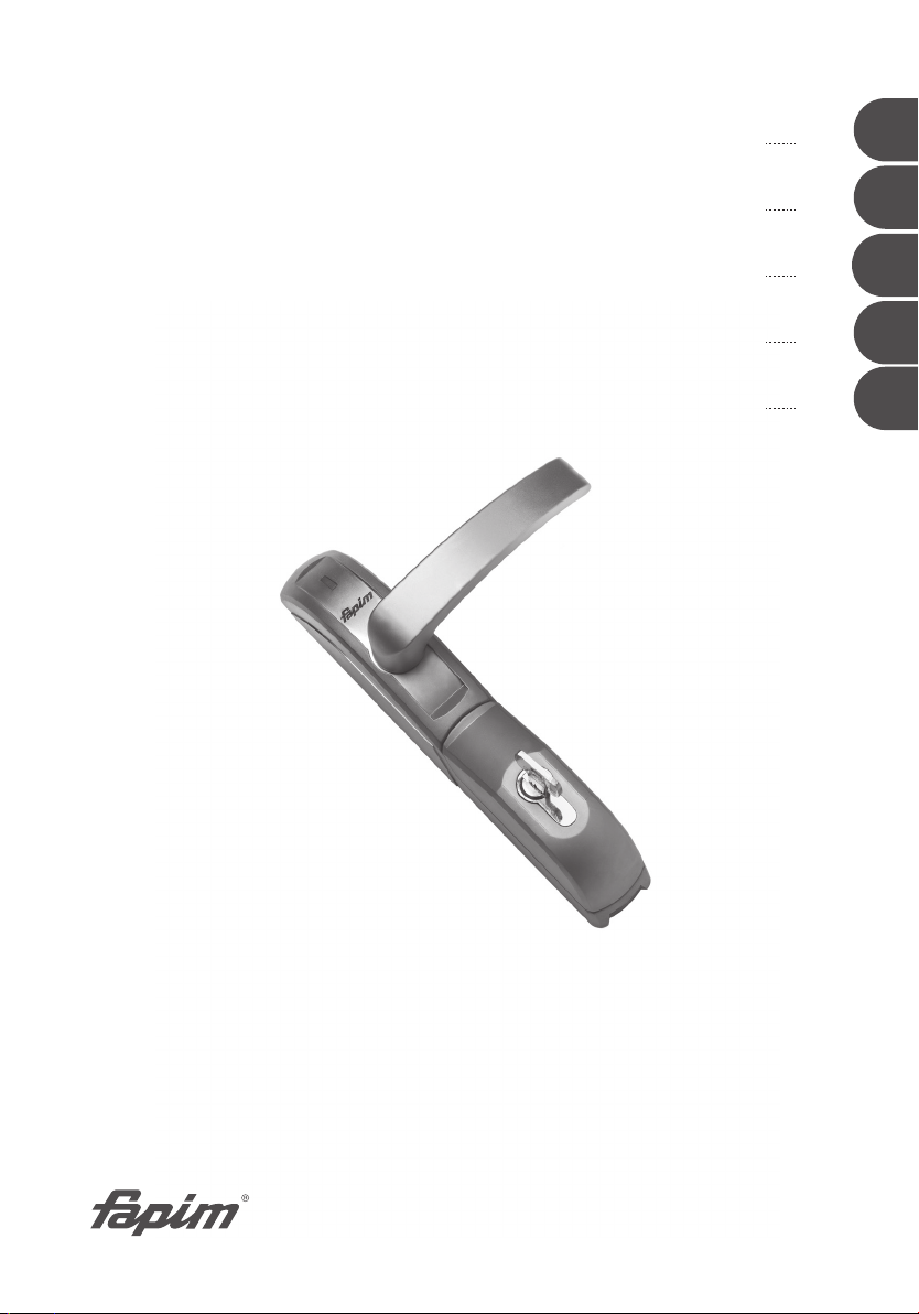
•Art. 8590B. Fissare la piastra
posteriore con le apposite viti,
accertandosi di posizionare le boccole
di fissaggio nelle posizioni compatibili
con i fori di fissaggio presenti sul
maniglione antipanico
•Accorciare il quadro d'azionamento in
dotazione e le viti di fissaggio
•Inserire il quadro d’azionamento
all’interno del nottolino
dell’elettromaniglia. Solo se necessario
bloccare il quadro con l'apposito grano
in dotazione.
•Effettuare le lavorazioni sull’anta come
da disegno
L=spessore porta +24 (+0/-1) L=spessore porta -5
ø9
ø9
ø18
8590A 8590B
Life in evolution
IT
5
8590A 8590B OLTRE
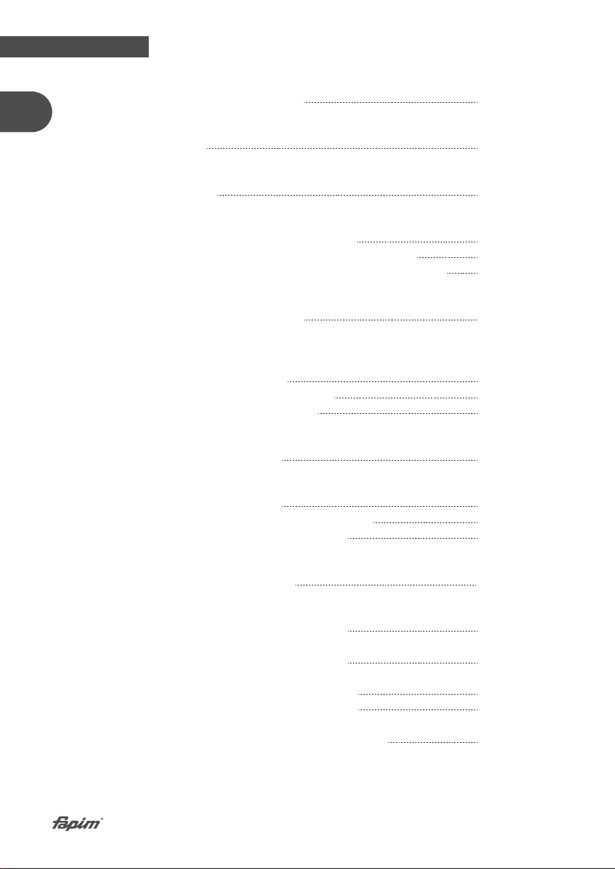
•Concludere il montaggio avvitando il
tutto con le viti precedentemente
portate a misura. Assicurarsi che le
parti in movimento siano libere e non
urtino parti dell'infisso o vadano in
contrasto con i meccanismi del
maniglione.
•Assicurarsi che durante il passaggio
del cavo questo non venga
involontariamente sguainato o
schiacciato.
8590A 8590B

IT
Life in evolution 6
8590A 8590BOLTRE
3. FUNZIONAMENTO
Attivazione con contatto pulito (con temporizzatore)
Art. 8590
L'elettromaniglia si presenta disabilitata (in folle) con il led di colore rosso acceso.
Premendo e rilasciando il pulsante di apertura il led commuta sul colore verde, la
maniglia consente l'apertura della porta. Questa condizione dura per il tempo
impostato sulla temporizzazione (da 5 a 60 secondi), o fino al primo azionamento della
maniglia. Per eseguire un’altra apertura è necessario premere nuovamente il pulsante
di apertura.
E' consigliato l'utilizzo di un passacavi ( art.8594C ).
4. REGOLAZIONE DELLA TEMPORIZZAZIONE
L'elettromaniglia è dotata internamente di un sistema di temporizzazione che permette
di mantenerla abilitata in modo temporizzato secondo le esigenze dell'utente.
4.1 Regolazione della temporizzazione a 0 secondi
1.Collegare il pulsante N.A. di programmazione (non incluso) al filo blu e al filo verde
della massa segnali (GND).
2.Alimentare l'elettromaniglia (fili grigio e bianco).
3.L'elettromaniglia si presenta con il led di colore rosso. Premere il pulsante di
programmazione fino al cambiamento di colore del led in blu. Rilasciare
immediatamente il pulsante di programmazione. Il led si accenderà per circa un
secondo confermando la programmazione. In questa modalità l'elettromaniglia rimarrà
abilitata soltanto per la durata dell'impulso elettrico.
4.2 Regolazione della temporizzazione da 5 a 60 secondi
1.Collegare il pulsante N.A. di programmazione (non incluso) al filo blu e al filo verde
della massa segnali (GND).
2.Alimentare l'elettromaniglia (fili grigio e bianco).
3.L'elettromaniglia si presenta con il led di colore rosso. Premere il pulsante di
programmazione fino al cambiamento di colore del led in blu. Mantenendo il pulsante
premuto il led eseguirà delle coppie di lampeggi che equivalgono ognuno a 5 secondi.
Rilasciare il pulsante di programmazione quando viene raggiunta la temporizzazione
desiderata. Il led confermerà la programmazione lampeggiando secondo la
temporizzazione scelta. In questa modalità l'elettromaniglia rimarrà abilitata per il
tempo selezionato o fino al primo azionamento della stessa.
8590A 8590B

Life in evolution
IT
7
8590A 8590B OLTRE
5. FERMO A GIORNO ELETTRICO
Nel caso si desiderasse mantenere la porta abilitata per un periodo di tempo a
discrezione dell'utente, è necessario montare in parallelo al pulsante di apertura un
interruttore che mantiene l'elettromaniglia abilitata fino al disinserimento dello stesso.
6. ABILITAZIONE E DISABILITAZIONE DEI LED BIANCO/BLU DI
ILLUMINAZIONE INFERIORE
L'elettromaniglia è dotata nella parte inferiore di led di colore blu (elettromaniglia
disabilitata) e bianco (elettromaniglia abilitata) che creano un fascio di luce verso il
pavimento.
6.1 Disabilitazione del led bianco/blu
1.Collegare il pulsante N.A. di programmazione (non incluso) al filo blu e al filo verde
della massa segnali (GND).
2.Con l'elettromaniglia disalimentata premere il pulsante di programmazione.
3.Alimentare l'elettromaniglia mantenendo il pulsante premuto.
4.Il led lampeggerà 1 volte di colore blu, rilasciando il pulsante il led diventerà rosso
confermando la disattivazione del led bianco/blu di illuminazione inferiore.
6.2 Abilitazione del led bianco/blu
1.Collegare il pulsante N.A. di programmazione (non incluso) al filo blu e al filo verde
della massa segnali (GND).
2.Con l'elettromaniglia disalimentata premere il pulsante di programmazione.
3.Alimentare l'elettromaniglia mantenendo il pulsante premuto.
4.Il led lampeggerà 1 volte di colore blu, rilasciando il pulsante il led diventerà rosso
confermando l’attivazione del led bianco/blu di illuminazione inferiore.
AVARIA
Se azionando elettricamente la maniglia il led rosso inizia a lampeggiare e il led blu
inferiore (se presente) si spegne vuol dire che c'è una situazione di “avaria”.
Per uscire da questa condizione togliere e ridare alimentazione all’elettromaniglia.
Nel caso il problema “avaria” si ripresentasse, verificare il corretto montaggio
meccanico e/o la fonte di alimentazione.
8590A 8590B

IT
Life in evolution 8
8590A 8590BOLTRE
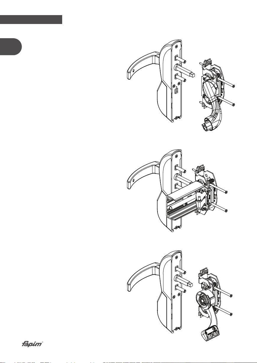
7. SOSTITUZIONE DEL CILINDRO
•Svitare la vite di bloccaggio cilindro
•Estrarre il cilindro
•Spostare il grano dal vecchio cilindro al
nuovo cilindro
•Reinserire il cilindro
•Avvitare la vite bloccaggio cilindro
•L’elettromaniglia è predisposta per il
montaggio di un mezzo cilindro a profilo
europeo con ingegno DIN. Lunghezza
cilindro = 40 (30+10).
CODICE CHIAVE SILCA GVY1R
8590A 8590B

8. ESEMPI DI INSTALLAZIONE
8.1 Elettromaniglia con Oltre Bar e Pad
8.2 Elettromaniglia con Oltre Push
Life in evolution
IT
9
8590A 8590B OLTRE
8590A 8590B
This manual suits for next models
2
Table of contents
Languages:
Other Fapim Lock manuals


