Far Tools EB 310 User manual

EB 310
EB 310
I
GB
F
E
D
RIVETTATRICE A BATTERIA
PER RIVETTI Ø 2,4 ÷ Ø 6 (Ø 6 SOLO ALLUMINIO)
ISTRUZIONI D’USO - PARTI DI RICAMBIO
BATTERY RIVETING TOOL
FOR RIVETS Ø 2.4 ÷ 6 (Ø 6 ALU ONLY)
INSTRUCTIONS FOR USE - SPARE PARTS
RIVETEUSE A BATTERIE
POUR RIVETS Ø 2,4 ÷ Ø 6 (Ø 6 ALU SEULEMENT)
MODE D’EMPLOI - PIECES DETACHEES
AKKU-NIETWERKZEUG
FÜR BLINDNIETE 2,4 ÷ 6 Ø (6 Ø NUR FÜR ALU)
BEDIENUNGSANLEITUNG - ERSATZTEILE
REMACHADORA DE BATERIA
PARA REMACHES Ø 2,4 ÷ Ø 6 (Ø 6 SOLO EN ALUMINIO)
INSTRUCCIONES DE USO - PIEZAS DE REPUESTO
NITOWNICA AKUMULATOROWA
DO NITÓW Ø 2,4 ÷Ø 6 (Ø 6TYLKO Z ALUMINIUM)
INSTRUKCJA OBSŁUGI - CZĘŚCI ZAMIENNE
ЗАКЛЁПЫВАЮЩИЙ АППАРАТ С АККУМУЛЯТОРОМ
ДЛЯ ЗАКЛЁПОК Ø 2,4 ÷ Ø 6 (Ø 6 ТОЛЬКО ИЗ АЛЮМИНИЯ)
ИНСТРУКЦИИ ПО ИСПОЛЬЗОВАНИЮ - ДЕТАЛИ
PL
RUS

EB 310
EB 310
Far S.r.l. - Giacomo Generali
(Presidente del Consiglio di Amministrazione)
(Chairman of the Board of Directors)
(Président du Conseil d’Administration)
(Vorsitzender des Verwaltungsrates)
(Presidente del Consejo de Administración)
(Prezes Zarzadu)
(Председатель Административного Совета)
.............................................
Quarto Inferiore, 28-12-2009
La sottoscritta Far S.r.l., con sede in Quarto Inferiore (BO)
alla via Giovanni XXIII n° 2,
DICHIARA
sotto la propria esclusiva responsabilità che la rivettatrice
Modello: EB 310 - Rivettatrice a batteria
Utilizzo: per rivetti diam. 2,4-6 (6 solo alluminio)
alla quale questa dichiarazione si riferisce è conforme ai
requisiti essenziali di sicurezza previsti dalla
Direttiva Macchine 2006/42/CE e successive modificazioni
ed integrazioni.
TheundersignedFarS.r.l.,havingitsofficeinQuartoInferiore
(BO), Via Giovanni XXIII No. 2, herewith
DECLARES
on its sole responsability that the riveting machine
Type: EB 310 - Battery tool
Application: for rivets diam. 2,4-6 (6 aluminium only)
whichis theobjectofthisdeclarationcomplieswiththebasic
safetyrequirements estabilishedin theMachineryDirective
2006/42/CE and subsequent amendments and integrations
LasociétéFarS.r.l.soussignéeavecsiègeàQuarto Inferiore
(BO), Via Giovanni XXIII n° 2,
DECLARE
sous sa seule responsabilité que la riveteuse
Modèle: EB 310 - Riveteuse à batterie
Utilisation: pour rivets diam. 2,4-6 (6 alu seulement)
à laquelle cette déclaration se rapporte est conforme aux
conditions essentielles de sécurité requises par le
Directive Machines 2006/42/CE et modifications et
intégrations successives.
Die Unterzeichnete, Fa. Far S.r.l., mit Sitz in Quarto Inferiore
(BO), Via Giovanni XXIII Nr. 2,
ERKLÄRT
hiermit auf ihre alleinige Verantwortung, daß die
Nietmaschine
Typ: EB 310 - Akku-Blindnietgerät
Anwendung: für Blindniete mit Durchmesser 2,4-6
(6 nur für Alu)
auf das sich diese Erklärung bezieht, den wesentlichen
Sicherheitsanforderungen der
Maschinenrichtlinie 2006/42/CE und den nachfolgenden
Änderungen und Anfügungen entspricht.
La firmataria Far S.r.l., domiciliada en Quarto Inferiore (BO)
en via Giovanni XXIII n° 2,
DECLARA
bajo su exclusiva responsabilidad que la remachadora
Modelo: EB 310 - Remachadora a batería
Empleo: para remaches diam. 2,4-6 ( 6 este último sólo
aluminio)
a la cual la presente declaración se refiere corresponde
a los requisitos esenciales de seguridad previstos por la
DirectivaMaquinas2006/42/CE y sucesivas modificaciones
e integraciones.
FirmaFARS.r.lzsiedzibąwQuartoInferiore(Włochy),ViaGiovanniXXIII,2
DEKLARUJE
na własną odpowiedzialność, że nitownica
Model: EB 310 - Nitownica akumulatorowa
Zastosowanie: do nitów o śr. 2,4-6 ( 6 tylko z aluminium )
jest zgodna wymogami norm bezpieczeństwa i Dyrektywą 2006/42/CE
z późniejszymi zmianami.
НижеподписавшeeсяFarS.r.l.,сместонахождениемвQuartoInferiore
(BO) ул. Giovanni XXIII, 2,
ЗАЯВЛЯЕТ
под свою собственную исключительную ответственность, что
заклёпывающий аппарат
Модель: EB 310 - Заклёпывающий аппарат с аккумулятором
Использование: для заклёпок диам. 2,4-6
( 6 только из алюминия )
ккоторомуотноситсянастоящаядекларациясоответствуетосновным
требованиям безопасности, предусмотренными Директивой
по машинам 2006/42/CE и последующими модификациями и
дополнениями.
I
GB
F
D
E
PL
RUS

ISTRUZIONI D’USO.................................................4
INSTRUCTIONS FOR USE.....................................10
MODE D’EMPLOI..................................................16
BEDIENUNGSANLEITUNG.....................................22
INSTRUCCIONES DE USO.....................................28
INSTRUKCJA OBSŁUGI.................................................34
ИНСТРУКЦИИ ПОA ИСПОЛЬЗОВАНИЮ ..........................40
PARTI DI RICAMBIO .............................................46
SPARE PARTS.......................................................47
PIECES DETACHEES .............................................48
ERSATZTEILE........................................................49
PIEZAS DE REPUESTO..........................................50
CZĘŚCI ZAMIENNE......................................................51
ДЕТАЛИ...................................................................52
EB 310
EB 310
I
I
F
F
E
E
PL
PL
RUS
RUS
GB
GB
D
D

I
EB 310
EB 310
Date 12-2009 Revision - 044
ISTRUZIONI D’USO I
INDICE
AVVERTENZE E MISURE DI SICUREZZA...............................4
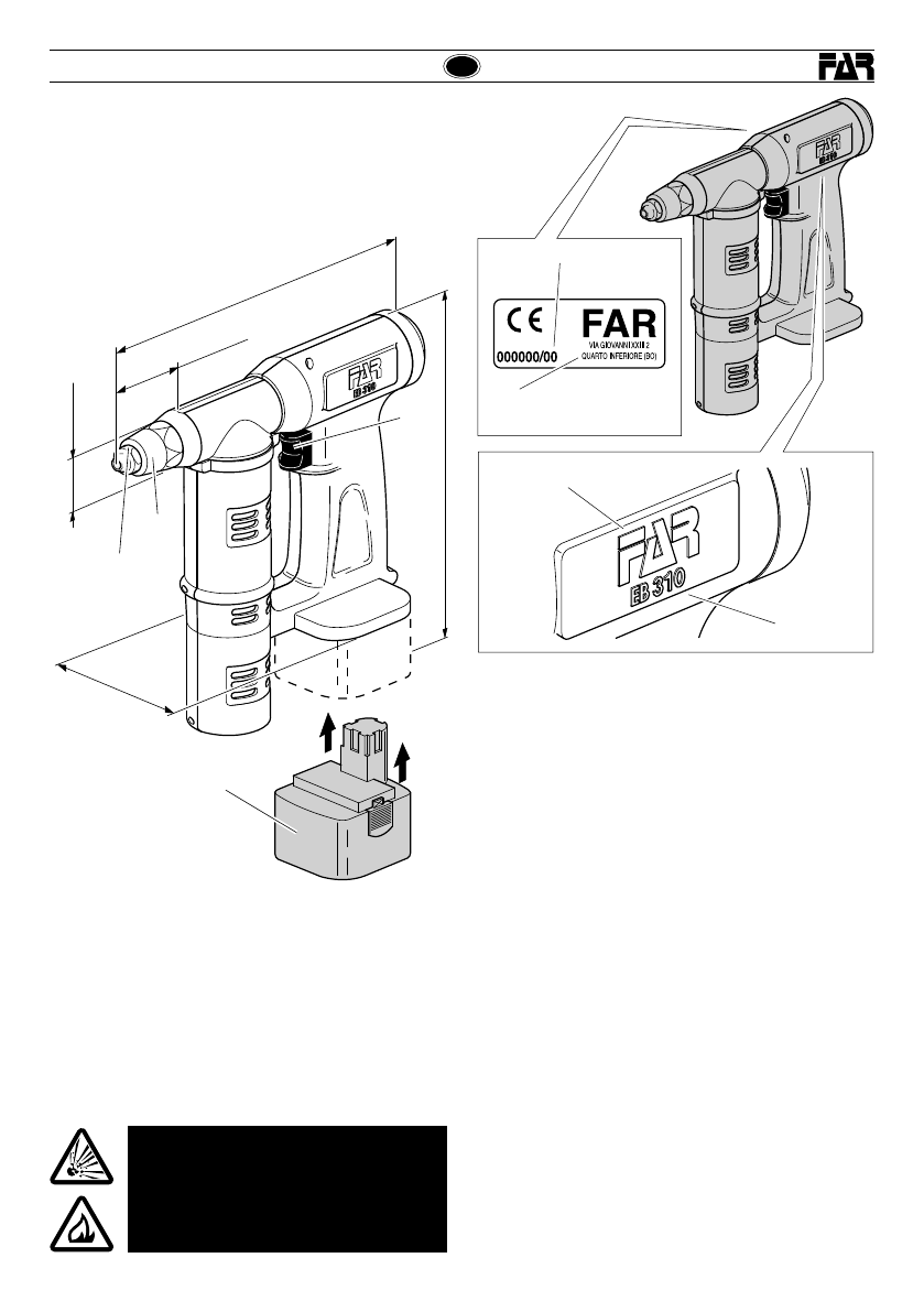
PARTI PRINCIPALI................................................................5
IDENTIFICAZIONE DELLA RIVETTATRICE.............................5
NOTE GENERALI E CAMPO DI APPLICAZIONE.....................5
DATI TECNICI........................................................................5
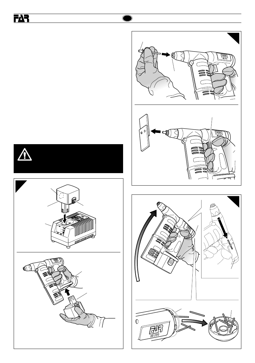
ALLACCIAMENTO ELETTRICO..............................................5
USO DELLA RIVETTATRICE ..................................................6
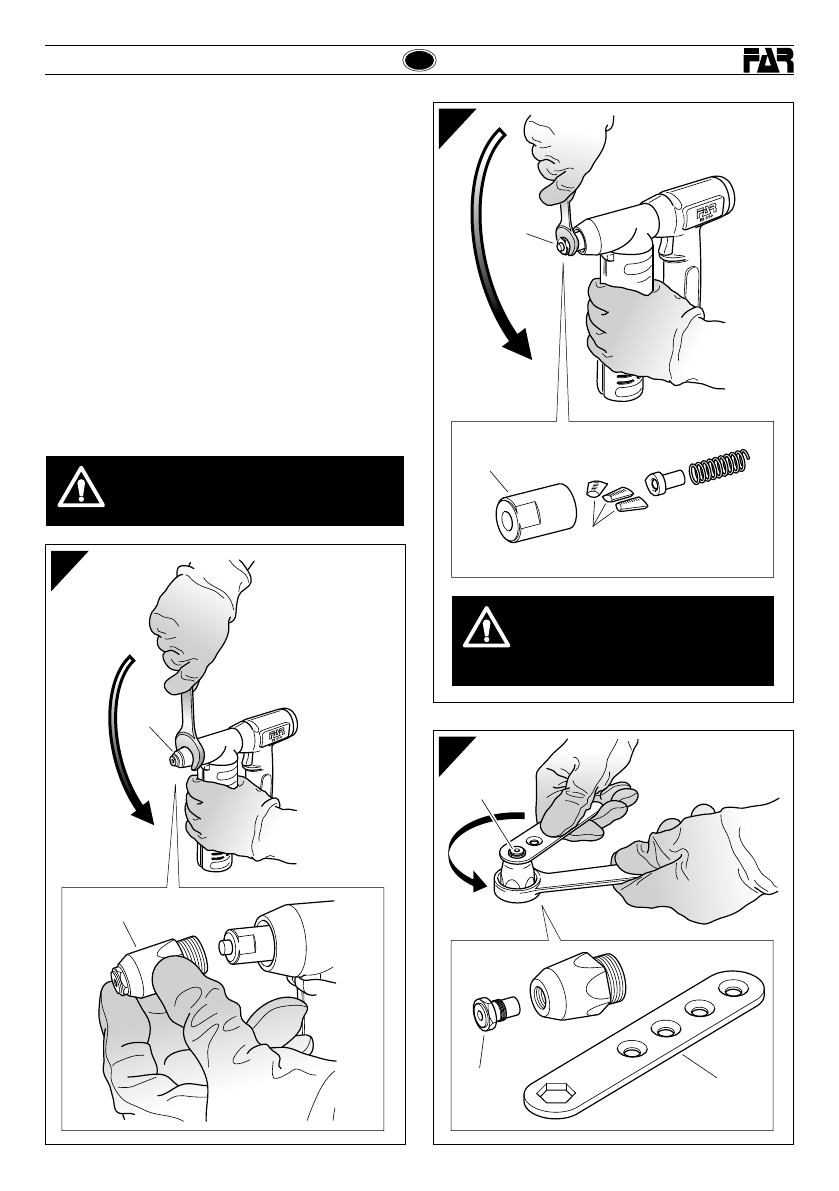
MANUTENZIONE E CAMBIO DI FORMATO............................7
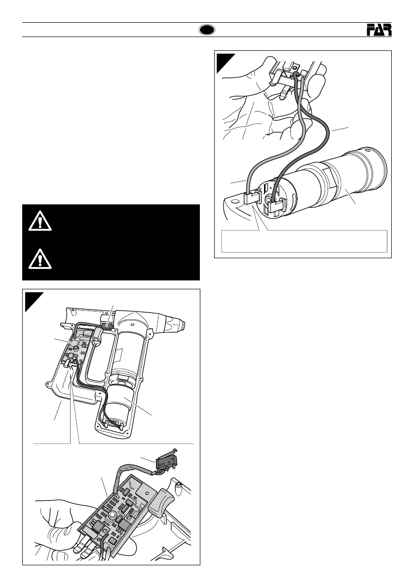
APERTURA DELLA MACCHINA.............................................8
RIMOZIONE E SOSTITUZIONE DEL
MICROINTERRUTTORE ........................................................8
RIMOZIONE E SOSTITUZIONE DELLA
SCHEDA ELETTRONICA........................................................9
BATTERIE..............................................................................9
AVVERTENZE E MISURE Dl SICUREZZA
ATTENZIONE!
La mancata osservanza o trascuratezza delle
seguenti avvertenze di sicurezza può avere
conseguenze sulla vostra o altrui incolumità e
sul buon funzionamento dell’utensile.
• Leggere attentamente le istruzioni prima dell’uso.
• Per le operazioni di manutenzione e/o riparazione affidarsi
a centri di assistenza autorizzati dalla FAR s.r.l. e fare uso
esclusivo di pezzi di ricambio originali. La FAR s.r.l. declina
ogni responsabilità per danni da particolari difettosi, che
si dovessero verificare per inadempienza di quanto sopra
(Direttiva CEE 85/374).
• Si raccomanda l’uso dell’utensile da parte di personale
specializzato.
• Usare, durante l’impiego dell’utensile, occhiali o visiere
protettive e guanti.
• Per eseguire le operazioni di manutenzione e/o di regolazione
dell’utensile utilizzare gli accessori in dotazione e/o le
attrezzature commerciali indicate nel capitolo Manutenzione.
• L’utensile può essere trasportato a mano ed è consigliabile
dopo l’uso riporlo nel proprio imballo.
• Si consiglia ai fini di un corretto funzionamento della
rivettatrice, una revisione semestrale.
• Gli interventi di riparazione e pulizia dell’utensile dovranno
essere eseguiti con macchina non alimentata.
• È consigliabile, ove possibile, I’uso di un bilanciatore di
sicurezza.
• In caso di esposizione quotidiana personale in ambiente il
cui livello di pressione acustica dell'emissione ponderata A
sia superiore al limite di sicurezza di 70 dB (A), fare uso di
adeguati mezzi individuali di protezione dell’udito (cuffia o
tappo antirumore, diminuzione del tempo di esposizione
quotidiana etc..).
• Mantenere il banco e/o l’area di lavoro pulita e ordinata, il
disordine può causare danni alla persona.
• Non lasciare che persone estranee al lavoro tocchino gli
utensili.
• Mantenere gli utensili in buono stato d’uso e puliti.
• Dopo avere eseguito operazioni di riparazione e/o registrazione
assicurarsi di avere rimosso le chiavi di servizio o di
registrazione.
• In caso di caduta dell’utensile controllarne la totale integrità.
• Accertarsi che il posto di lavoro sia libero da impedimenti.
• Il posto di lavoro deve essere sempre in ordine e ben
illuminato. In particolare non devono essere presenti liquidi
e gas infiammabili.
• Non lavorare in ambienti umidi o bagnati nè tantomeno sotto
la pioggia.
• Non utilizzare l’utensile in prossimità di fiamme libere.
• Eseguire i lavori per i quali l’utensile è stato costruito, non
rischiare danni in lavori inadeguati.
• Nel lavoro mantenere sempre una posizione sicura e un buon
equilibrio, usando idonee calzature.
• Usare un utensile di potenza adeguata al lavoro da svolgere,
evitando inutili sovraccarichi, rischiosi per l’operatore e
dannosi per la durata dell’utensile stesso.
• Attenersi scrupolosamente a queste istruzioni.
• Riporre la batteria in luogo asciutto e sicuro.
• Qualora la batteria presenti danni alla sua struttura sostituirla
con una batteria nuova.
• Se la batteria avesse delle perdite di liquido fare attenzione
a non venirne a contatto con la pelle.
• Nel caso di contatto epidermico lavarsi immediatamente con
acqua e sapone, poi ricorrere subito alle cure di un medico.
• Nel caso gli occhi vengano a contatto con il liquido della batteria
occorre sciacquarli immediatamente con acqua pulita per almeno
dieci (10) minuti, e ricorrere subito alle cure di un medico.
• Non usare batterie di modello diverso da quella fornita.
• Assicurarsi che le superfici esterne della batteria siano
asciutte e pulite prima di inserirla nell’apposito carica-
batteria.
• Utilizzare esclusivamente il carica-batteria proposto dalla
FAR s.r.l. onde evitare scariche elettriche, surriscaldamenti
o perdite di liquidi corrosivi dalla batteria.
• Le batterie possono essere dannose per l’ambiente e possono
esplodere se esposte al fuoco o altre fonti di calore, pertanto
non disperdere le batterie nell’ambiente e non incenerirle.
Smaltire le batterie non più utilizzabili secondo le norme
vigenti nel paese di utilizzo.

Revision - 04 Date 12-2009 5
I
EB 310
EB 310
Nome del costruttore
Modello
PARTI PRINCIPALI
A)..................................................................................Ugello
B)................................................................Testa porta ugello
C)..............................................................................Pulsante
D)................................................................................Batteria
DATI TECNICI
• Tensione di alimentazione............................................ 12 V
• Peso......................................................................2,600 Kg
• Temperatura di utilizzo...........................................-5°/+50°
• Valore medio quadratico ponderato in frequenza
dell’accelerazione complessiva (Ac) a cui sono
sottoposte le membra superiori..................... < 2,5 m/sec2
• Pressione acustica dell’emmissione ponderata (A) . 80 dBA
• Pressione acustica istantanea ponderata (C) ......<130 dBC
• Pressione acustica ponderata (A) ...........................86 dBA
ALLACCIAMENTO ELETTRICO
La rivettatrice EB 310 utilizza come fonte di energia una batteria
ricaricabile tipo APPA 12V / 2,0 Ah. Il tempo di ricarica ottimale
per la batteria è di 50 minuti.
Per effettuare la ricarica della batteria utilizzare esclusivamente
il carica-batteria FAR modello LGPA-1230.
Per le varie nozioni riguardanti il caricabatteria LGPA-1230
fare esclusivamente riferimento al manuale fornito unitamente
allo stesso.
Primadiinserirelaspinadelcarica-batteriaallapresadicorrente,
accertarsi che il valore della tensione in linea corrisponda a
quello contrassegnato sulla targhetta presente sullo stesso.
Accertarsi che l’impianto elettrico generale sia dimensionato
per sopportare il carico di targa richiesto (vedi dati tecnici).
Assicurarsi che l’impianto elettrico sia stato realizzato secondo
le norme di legge in vigore.
Il cavo di alimentazione è munito di una apposita spina che va
inserita in una presa dello stesso tipo.
ATTENZIONE!
Ilpostodilavorodeveesseresempreinordine
e ben illuminato.
In particolare non devono essere presenti
liquidi e gas infiammabili.
IDENTIFICAZIONE DELLA RIVETTATRICE
La rivettatrice EB 310 è identificata dal nome del costruttore e
modello. In caso di richiesta di assistenza tecnica fare sempre
riferimento ai dati riportati sulla rivettatrice.
NOTE GENERALI E CAMPO DI APPLICAZIONE
L’uso dell’utensile è finalizzato esclusivamente all’utilizzo
di rivetti a strappo di diametro compreso tra Ø 2,4 e 6 mm.
Il diametro Ø 6 mm può essere impiegato solo per rivetti in
alluminio.
235 mm
Ø 29
235 mm
45 mm
82 mm
A
B
C
D
Matricola e anno di
produzione
Nome e indirizzo del
costruttore

I
EB 310
EB 310
Date 12-2009 Revision - 046
f1
USO DELLA RIVETTATRICE (fig. f1-f2-f3)
Perun rendimento ottimale della rivettatricesi raccomanda che
l’operatore, ai primi segnali di affaticamento durante il ciclo di
serraggio, riponga la batteria (D) nel relativo carica batteria (E)
(modello LGPA-1230).
Inserire la batteria (D) nella parte inferiore della rivettatrice (F),
facendo attenzione al corretto aggancio.
Per scollegare la batteria dalla rivettatrice premere i pulsanti
(D1) e sfilarla.
Per la messa in posa inserire il rivetto (G) nell’ugello (A),
premereil pulsante(C). Percontenere il chiodo troncato dopoil
serraggio, ruotare la rivettatrice verso l’alto così facendo verrà
guidato all’interno dell’apposito contenitore (H) presente nella
parte posteriore della rivettatrice.
Attenzione:accertarsichelarivettatricesiadotatadell’apposito
tappo di chiusura (I) del contenitore dei chiodi, evitare di
contenere al suo interno un numero eccessivo di chiodi, che
causerebbe l’arresto della rivettatrice.
Vuotare regolarmente.
ATTENZIONE!!!
I chiodi tranciati devono essere raccolti in un
apposito contenitore.
Non disperdere i chiodi nell’ambiente.
Nel caso di utilizzo continuativo dell’utensile, ogni due
sostituzioni della batteria, lasciare raffreddare la rivettatrice
completamente.
D
F
E
D1
D1
D
f2
G
A
C
H
I
I
I
f3

Revision - 04 Date 12-2009 7
I
EB 310
EB 310
ATTENZIONE!
Effettuarele suddette operazionicon rivettatrice
non alimentata.
MANUTENZIONE E CAMBIO DI FORMATO (fig. f4-f5-f6)
L’utilizzoprolungatodella rivettatricepuòdarluogoalloslittamento
dei morsettl sul chiodo causato dal deposito di impurità. Si
dovrà quindi procedere alla pulizia dei suddetti morsetti ed
alla successiva lubricazione oppure, in caso di usura che ne
comprometta il corretto funzionamento, alla loro sostituzione.
Smontare il cannotto porta ugello (B) servendosi di una chiave
commercialedimm27.Unavoltarimossoilcannottoportaugello,
servirsi di chiave commerciale di mm 16 per smontare il cono (L)
dacuisaranno estratti i morsetti (M). Per la sostituzione dell’ugello
(A) servirsi dell’apposita chiave in dotazione (N) e avvitare su di
essal’ugellorimossodallarivettatriceinmododanondisperderlo.
Nota bene: l’utilizzo prolungato della rivettatrice può dar luogo
al normale deperimento del microinterruttore, del motore o della
scheda elettronica presenti all’interno della impugnatura. Per
evitare di danneggiare ulteriormente la rivettatrice procedere
alla sostituzione del microinterruttore, del motore o della scheda
(vedi capitoli successivi).
f4
B
B
f5
f6
AN
A
L
L
M
ATTENZIONE!
Il mancato bloccaggio del cono porta
morsetti può causare gravi danni
economici alla rivettatrice.

I
EB 310
EB 310
Date 12-2009 Revision - 048
APERTURA DELLA MACCHINA (fig. f7)
Togliere la batteria (D) ed il tappo di chiusura serbatoio chiodi (I),
smontare il guscio (O) servendosi di cacciavite commerciale con
testa a croce di mm 4 per rimuovere le 12 viti (P) di fissaggio.
RIMOZIONE E SOSTITUZIONE DEL MICROINTERRUTTORE
(fig. f8)
Estrarre il microinterruttore (Q) dal proprio alloggiamento,
scollegarlodaicaviesostituirloconilnuovo.Nonesistesequenza
di connessione. Riporre il microinterruttore (Q) orientato come
mostrato in figura, all’interno del guscio (R) facendo attenzione
al corretto posizionamento di tutti i cavi e chiudere la rivettatrice
utilizzando le 12 viti (P) precedentemente smontate.
ATTENZIONE!
Fare eseguire queste operazioni da personale
autorizzato e specializzato, inoltre utilizzare
esclusivamente i ricambi originali.
f7
f8
PP
P
P
P
P
D
P
P
P
P
IB
P
O
R
Q
R
Q
Q

Revision - 04 Date 12-2009 9
I
EB 310
EB 310
RIMOZIONE E SOSTITUZIONE DELLA SCHEDA
ELETTRONICA (fig. f9-f10)
Dopo avere tolto la batteria e smontato il guscio come
precedentemente descritto, estrarre la scheda (S) con il
microinterruttore (Q) dal guscio (R), scollegarla dal motore
(T) e sostituirla con la nuova.
Collegare nuovamente i cavi al motore rispettando le due
diverse polarità:
Polo Positivo (+) = Cavo Rosso.
Attenzione! Il polo positivo è identicato dal riferimento
rosso posto sul retro del motore.
Riporre la scheda (S) con il microinterruttore (Q) (come
precedentemente descritto a pag. 8) all’interno del guscio (R)
facendo attenzione al corretto posizionamento di tutti i cavi e
chiuderela rivettatrice utilizzando le 12viti(P)precedentemente
smontate.
BATTERIE
La batteria al Nickel-Cadmio APPA 12V/2,0 Ah, per rivettatrice a
batteria FAR EB 310 può essere ricaricata più volte per dare una
maggiore durata ed una piena potenza.
• Riporre la batteria in luogo asciutto e sicuro.
• Qualora la batteria presenti danni alla struttura, sostituirla
con una batteria nuova.
•
Noncortocircuitareicontatti; ciòpuòesserecausadiincendied
esplosioni.Nell’eventualitàsiverificasseroperditediliquidodalla
batteria, fare attenzione che lo stesso non venga a contatto
con la pelle.
In caso di:
1) Contatto epidermico, lavarsi immediatamente ed
accuratamenteconacqua e sapone,poiricorrere subito
alle cure di un medico.
2) Contatto con gli occhi, sciacquarli abbondantemente
con acqua pulita per almeno 10 minuti, poi ricorrere
subito alle cure di un medico.
• Non usare batterie di modello diverso da quella fornita.
• Assicurarsichelesuperficiesternedellebatteriasianosempre
asciutteepuliteprimadiinserirlanell’appositocarica-batteria.
• Utillizzareesclusivamenteilcarica-batteriaoriginaledellaFAR
S.r.l. onde evitarechelabatteriaproduca scariche elettriche,
surriscaldamenti o perdite di liquidi corrosivi.
• Le batterie Nickel-Cadmio possono essere dannose per
l’ambiente e possono esplodere: non tentare di aprirle, non
esporle al fuoco o altre fonti di calore e proteggerle da urti.
Non incenerire. Non disperdere nell’ambiente.
• Smaltire le batterie, accessori ed imballaggio non più
utilizzabili secondo le norme vigenti nel paese di utilizzo.
• L’utilizzatoreèresponsabiledel corretto smaltimentodella
batteria.
ATTENZIONE!
Fare eseguire queste operazioni da personale
autorizzato e specializzato, inoltre utilizzare
esclusivamente i ricambi originali.
ATTENZIONE!
Per la rimozione e sostituzione del motore (T)
rivolgersi ai centri assistenza FAR.
f9
S
RT
S
Q
Q
f10
T
+
-
Polo Positivo (+) = Cavo Rosso

GB
EB 310
EB 310
Date 12-2009 Revision - 0410
INSTRUCTIONS FOR USE I
INDEX
SAFETY MEASURES ...........................................................10
MAIN COMPONENTS..........................................................11
IDENTIFYING THE TOOL.....................................................11
GENERAL NOTES AND APPLICATION.................................11
TECHNICAL SPECIFICATIONS.............................................11
ELECTRICAL CONNECTION.................................................11
HOW TO USE YOUR RIVETING TOOL.................................12
MAINTENANCE AND SIZE CHANGE....................................13
OPENING THE TOOL...........................................................14
REMOVING AND REPLACING THE MICROSWITCH............14
REMOVAL AND REPLACEMENT OF THE
ELECTRONIC PRINT-CIRCUIT BOARD (P.C.B.)...................15
BATTERIES..........................................................................15
SAFETY MEASURES AND REQUIREMENTS
CAUTION!!!
All the operations must be done in conformity
with the safety requirements, in order to avoid
any consequence for your and other people’s
security and to allow the best tool work way.
• Read the instructions carefully before using the tool.
• For all maintenance and/or repairs please contact FAR s.r.l.
authorized service centers and use only original spare parts.
FAR s.r.l. may not be held liable for damages from defective
parts caused by failure to observe what above mentioned
(EEC directive 85/374).
• Only skilled personnel may use the tool.
• Wear safety goggles or masks and work gloves while using
the tool.
• Use the accessories provided and/or the commercial
equipment recommended in the Maintenance chapter for all
maintenance and/or adjustments to the tool.
• The tool is portable; we recommend storing it in its box after
use.
• The tool should be overhauled every six months to ensure
smooth operation.
• Do not perform any repair or clean the tool while it is powered.
• Where possible, we recommend using a safety balancer.
• If the A-weighted emission sound pressure level is more than
70 dB (A), you must use some hearing protections (anti-noise
headset, etc.).
• Keep the workbench and/or work area neat and clean;
untidiness can lead to accidents.
• Do not allow unauthorized person to touch the tools.
• Keep tools clean and in good working condition.
• Make sure all service or setting keys have been removed after
performing repairs and/or adjustments.
• If the tool is dropped, check it carefully for any damage.
• Make sure the work area is free of any obstacle.
• The work area must always be kept neat and well-lit. In
particular, flammable liquids or gases must not be present.
• Do not work in damp or wet areas, and especially not in the
rain.
• Do not use the tool near open flames.
• Use the tool only for its intended purpose; do not risk causing
damage through inappropriate use.
• Stand in a safe, well-balanced position while working. Wear
appropriate shoes.
• Make sure the tool power is suited to the task at hand. Avoid
unnecessary overloads, which are hazardous to the operator
and detrimental to the life-span of the tool itself.
• Follow these instructions closely.
• Store the battery in a safe, dry place.
• If the battery structure is damaged, replace it with a new one.
• Be careful to avoid skin contact if the battery leaks fluid.
• In case of accidental skin contact, wash the area thoroughly
with soap and water and contact a doctor immediately.
• In case of eye contact with the battery fluid, rinse eyes with
abundant running water for ten (10) minutes at least. Contact
a doctor immediately.
• Do not use any battery model other than the one provided.
• Make sure the outer surfaces of the battery are clean and dry
before inserting it in the battery charger.
• Use only battery charger provided by FAR S.r.l. to avoid
sparks, overheating or battery fluid leakage.
• The batteries may be harmful to the environment, and may
explode if exposed to fire or other sources of heat. Do not
litter or incinerate. Dispose of batteries according to current
regulations in your country.

Revision - 04 Date 12-2009 11
GB
EB 310
EB 310
Name of manufacturer
Model
MAIN COMPONENTS
A) ................................................................................ Nozzle
B) .........................................................................Nozzlehead
C) ................................................................................Button
D) ............................................................................... Battery
TECHNICAL SPECIFICATIONS
• Supply voltage............................................................. 12 V
• Weight ..................................................................2.600 Kg
• Operating temperature...........................................-5°/+50°
• Root weighted mean square of overall
acceleration frequency (Ac)
to which arms are subjected.......................... < 2.5 m/sec2
• A-weighted emission sound pressure level ............80 dBA
• Peak C-weighted instantaneous sound pressure <130 dBC
• A-weighted emission sound pressure .....................86 dBA
ELECTRICAL CONNECTION
The EB 310 riveting tool is powered by an APPA 12V / 2,0 Ah
rechargeable battery. The ideal recharging time for the battery
is 50 minutes.
Use only FAR battery charger model LGPA-1230 to recharge
this battery.
For miscellaneous information about LGPA-1230 battery
charger, see theinstructionbooklet provided withtheunititself.
Beforepluggingthe batterychargerintothepowersocket,make
sure that the line voltage corresponds to the value indicated on
the battery charger label.
Makesure themainelectricalsystemisproperlysizedto support
the rated charge (see technical specifications).
Make sure the electrical system complies with current
regulations.
The power cord has a plug that must be inserted into a
matching socket.
WARNING!
The work area must always be kept neat
and well-lit.
Inparticular, flammable liquids orgases must
not be present.
IDENTIFYING THE TOOL
The EB 310 riveting tool has a label bearing the name of the
manufacturer and the tool model.
Always refer to the information on the riveting tool when
requesting technical service.
GENERAL NOTES AND APPLICATION
The tool is intended solely for use with rivets having a diameter
between 2.4 and 6 mm.
Those with a 6-mm diameter may be used only in aluminum.
235 mm
Ø 29
235 mm
45 mm
82 mm
A
B
C
D
Serial number and
manufacturing year
Name and address of
manufacturer

GB
EB 310
EB 310
Date 12-2009 Revision - 0412
f1
HOW TO USE YOUR RIVETING TOOL (fig. f1-f2-f3)
For an ideal performance of the riveting tool, we recommend
that the operator, after the first symptoms of fatigue during the
fastening cycle, inserts the battery (D) into the battery charger
(E) (model LGPA-1230).
Insert the battery (D) into the bottom of the riveting tool (F) as
shown in the figure, making sure it snaps into place.
To remove the battery from the tool, press the buttons (D1)
and slide it out.
To use the tool, insert the rivet (G) into the nozzle (A) and
press the tensil strength button (C). To collect the truncated
stem after riveting, turn the tool head face up to allow to the
nail to reach the proper container (H) on the back of the tool.
Warning:besurethatthetoolisequippedwiththenailcontainer
closing cap (I), avoid to collect an excessive quantity of nails
that could block the tool.
Empty regularly.
WARNING!
Keep truncated stems in a specific container.
Dispose of stems properly.
If the riveting tool is used continuously, let it cool completely
every other time the battery is changed.
D
F
E
D1
D1
D
f2
G
A
C
H
I
I
I
f3

Revision - 04 Date 12-2009 13
GB
EB 310
EB 310
WARNING!
The riveting tool must be shut off during the
above operations.
MAINTENANCE AND SIZE CHANGE (fig. f4-f5-f6)
Prolongeduse of theriveting tool maycause the clampstoslide
alongthe stemdue to built-up grime. You must thereforeclean
and lubricate the clamps, or replace them if heavily worn to
the point of preventing correct use.
Use a 27-mm commercial wrench to remove the tube carrying
nozzle (B). Once the tube has been removed, use a commercial
wrench-16 mm -toremove the cone(L)andextract the clamps
(M). To replace the nozzle (A), use the supplied special key (N)
and place on it the removed nozzle to avoid any loss.
Please note: prolonged use of the riveting tool may cause a
normal wear of the microswitch, of the motor or of the printed-
circuit board inside the handgrip. To avoid a further damage of
the tool, proceed in replacing the microswitch, the motor or the
printed-circuit board (see following chapters).
f4
B
B
f5
f6
AN
A
L
L
M
WARNING!
If the clamps holding cone is not well
locked,therivetingtoolmaybeseriously
damaged.

GB
EB 310
EB 310
Date 12-2009 Revision - 0414
OPENING THE TOOL (fig. f7)
Remove the battery (D) and the nail container closing cap (I),
disassemble the housing (O) of the tool, using a common
screwdriver of 4 mm to remove the 12 holding screws (P).
REMOVING AND REPLACING THE MICROSWITCH (fig. f8)
Extract the microswitch (Q), disconnect the wires and replace
the microswitch with the new one. A connection sequence
does not exist.
Place the microswitch (Q) inside the housing (R) oriented as
showninfigure,takingcareofproperpositioningofallwires,and
assemble the tool using the 12 screws (P) previously removed.
WARNING!
Only skilled, authorized personnel may perform
these operations.
Use only original spare parts.
f7
f8
PP
P
P
P
P
D
P
P
P
P
IB
P
O
R
Q
R
Q
Q

Revision - 04 Date 12-2009 15
GB
EB 310
EB 310
REMOVAL AND REPLACEMENT OF THE ELECTRONIC
PRINT-CIRCUIT BOARD (P.C.B.) (fig. f9-f10)
After removing the battery and disassembling the housing as
previously described, extract the electronic p.c.b. (S) together
with the microswitch (Q) from the housing (R), disconnect it
frommotor (T) and replace the electronicp.c.b. witha new one.
Connect the wires to the motor again, respecting the two
different polarities:
Positive Pole (+) = Red Wire.
Warning! The positive pole is identied with a red mark on
the back of the motor.
Place the electronic p.c.b. (S) with the microswitch (Q) inside
the housing (R) as previously described at page 14, taking care
of proper positioning of all wires, and assemble the tool using
the 12 screws (P) previously unscrewed.
BATTERIES
The APPA 12V/2.0 Ah nickel-cadmium battery for the battery-
operated FAR EB 310 riveting tool may be recharged several
times, for a longer life-span and full power yield.
• Store the battery in a safe, dry place.
• If the battery structure is damaged, replace it with a new
one.
• Donotshort-circuitthecontacts,whichmaycausefire and
explosions. Be careful to avoid skin contact if the battery
leaks fluid.
In case of:
1) Accidental skin contact, wash the area thoroughly
withsoap and waterandcontactadoctorimmediately.
2) Accidental eye contact, rinse eyes with abundant
running water for at least 10 minutes. Contact a
doctor immediately.
• Do not use any battery model other than the one provided.
• Make sure the outer surfaces of the battery are clean and
dry before inserting it in the battery charger.
• Use only the battery charger provided by FAR S.r.l. to
avoid sparks, overheating or battery fluid leakage.
• Nickel-cadmium batteries may be harmful to the
environment and may explode. Do not attempt to open
them. Do not expose to fire or other sources of heat. Do
not incinerate. Do not litter.
• Dispose of batteries according to current regulations in
your country.
• The user is directly responsible for proper disposal of
batteries.
WARNING!
Only skilled, authorized personnel may perform
these operations.
Use only original spare parts.
WARNING!
For removal and replacement of the motor (T)
please contact our service centres.
f9
S
RT
S
Q
Q
f10
T
+
-
Positive pole (+) = Red wire

F
EB 310
EB 310
Date 12-2009 Revision - 0416
MODE D’EMPLOI I
INDEX
INSTRUCTIONS ET MESURES DE SECURITE.....................16
PARTIES PRINCIPALES ......................................................17
IDENTIFICATION DE LA RIVETEUSE ...................................17
CARACTERISTIQUES ET EMPLOI .......................................17
DONNEES TECHNIQUES .....................................................17
BRANCHEMENT ELECTRIQUE ............................................17
MODE D’EMPLOI DE LA RIVETEUSE ..................................18
ENTRETIEN ET CHANGEMENT DE BUSES ..........................19
OUVERTURE DE LA RIVETEUSE.........................................20
ENLEVEMENT ET REMPLACEMENT DU
MICROCONTACT.................................................................20
ENLEVEMENT ET REMPLACEMENT DE LA CARTE
ELECTRONIQUE..................................................................21
BATTERIES..........................................................................21
INSTRUCTIONS ET MESURES DE SECURITE
ATTENTION!!!
Le non respect des instructions suivantes
peut avoir des conséquences désagréables
pour vous-mêmes et pour l’intégrité d’autrui.
• Lisez avec soin la notice avant l’usage.
• Pour les opérations d’entretien et/ou réparations, adressez-
vous aux centres de service après-vente autorisés de FAR
s.r.l. et n’utilisez que des pièces détachées originales.
FAR s.r.l. décline toute responsabilité pour les dommages
dus à des pièces défectueuses qui interviendraient suite au
non-respect de la notice ci-dessus (Directive CEE 85/374).
• La riveteuse ne doit être utilisée que par du personnel
spécialisé.
• Avant l’usage, il faut se munir d’une visière et de gants de
protection.
• Pour l’entretien et/ou les réglages de la riveteuse, se servir
des accessoires fournis et/ou des équipements indiqués au
chapitre Entretien.
• La riveteuse peut être transportée à main et elle doit être
remise dans son emballage après l’usage.
• Pour un bon fonctionnement de la riveteuse, nous vous
suggérons de la réviser tous les six mois.
• Les réparations et le nettoyage de la riveteuse ne doivent être
effectués que quand la riveteuse n’est pas branchée.
• Si possible, utilisez des équilibreurs de sécurité.
• En cas d’exposition quotidienne où le niveau de pression soit
supérieur à la limite de sécurité 70 dB (A), l’on doit s’assurer
la protection de l’ouïe (casque antibruit, réduction du temps
d’exposition quotidienne, etc).
• La table et le poste de travail doivent être toujours propres
et rangés. Le désordre peut causer des dommages aux
personnes.
• Veiller à ce qu’aucune personne étrangère utilise la riveteuse.
• La riveteuse dot être toujours en bon état.
• Après la réparation et/ou le réglage, il faut s’assurer d’avoir
enlevé les clés de réglage.
• En cas de chute de la riveteuse, contrôlez son intégrité.
• Assurez-vous que la zone de travail est dégagée.
• Le poste de travail doit toujours être en ordre et bien éclairé.
En particulier, aucun liquide ou gaz inflammable ne devra être
présent.
• Ne travaillez pas dans un milieu humide ou mouillé, ni sous
la pluie.
• N’utilisez pas la riveteuse à proximité d’une flamme.
• N’exécutez que les travaux pour lesquels la riveteuse a été
conçue. Ne risquez pas de causer des dégâts avec des travaux
inadéquats.
• Lors du travail, maintenez toujours une position sûre et un
bon équilibre et utilisez des chaussures adéquates.
• Utilisez une riveteuse de puissance correspondant au travail à
effectuer. Evitez des surcharges inutiles et dangereuses pour
l’opérateur et néfastes pour la durée de vie de a riveteuse.
• Suivre scrupuleusement ces instructions.
• Conservez la batterie dans un endroit sec et protégé.
• Si la structure de la batterie est endommagée, remplacez-la
par une nouvelle batterie.
• Si la batterie présente des pertes de liquide, veillez à ce que
votre peau n’entre pas en contact avec le liquide.
• En cas de contact avec votre peau, laver immédiatement avec
du savon et consultez un médecin.
• Si le liquide de la batterie entre en contact avec vos yeux, il
faut d’abord rincer les yeux à l’eau propre pendant au moins
dix (10) minutes. Ensuite, consultez un médecin.
• N’utilisez pas de batterie d’un modèle différent du modèle
fourni.
• Assurez-vous que les surfaces externes de la batterie sont
sèches et propres avant de l’introduire dans le chargeur.
• N’utilisez que le chargeur proposé par FAR s.r.l. Cela vous
évitera toutes décharges électriques, surchauffes ou pertes
de liquides corrosifs de la batterie.
• Les batteries peuvent être nuisibles à l’environnement. Elles
peuvent exploser si exposées au feu ou à d’autres sources de
chaleur. N’abandonnez pas les batteries dans l’environnement
et ne les brûlez pas. Eliminez les batteries inutilisables dans
le respect des normes en vigueur dans le pays d’utilisation.

Revision - 04 Date 12-2009 17
F
EB 310
EB 310
Nom du constructeur
Modèle
PARTIES PRINCIPALES
A)....................................................................................Buse
B)................................................................... Tête porte buse
C)................................................................................ Bouton
D)................................................................................Batterie
DONNEES TECHNIQUES
• Tension d’alimentation................................................. 12 V
• Poids ....................................................................2,600 Kg
• Température d’utilisation ........................................-5 /+50°
• Valeur moyenne quadratique pondérée en
fréquence de l’accélération
totale (Ac) à laquelle les bras sont soumis .... < 2,5 m/sec2
• Pression acoustique de l’émission pondéré (A) .....80 dBA
• Pression acoustique instantanée pondéré (C) ..... <130 dBC
• Puissance acoustique pondérée (A) ........................ 86 dBA
BRANCHEMENT ELECTRIQUE
La riveteuse EB 310 utilise une batterie rechargeable du type
APPA 12V / 2,0 Ah. La durée de recharge optimale de la batterie
est de 50 minutes. Pour recharger la batterie, il faut utiliser
seulement le chargeur de batterie FAR modèle LGPA-1230.
Pour les informations concernant le chargeur de batterie
LGPA-1230, nous vous prions de consulter la notice fournie
avec le chargeur.
Avant de brancher le chargeur à la prise de courant, assurez-
vous que la valeur de tension du réseau correspond à la valeur
figurant sur la plaquette collée sur le chargeur.
Assurez-vous que l’installation électrique générale est
dimensionné pour supporter la charge nominale demandée
(voir données techniques).
Assurez-vous que l’installation électrique est réalisée dans le
respect des normes en vigueur.
Le câble d’alimentation est équipé d’une fiche qui doit être
introduite dans une prise du même type.
ATTENTION!
Le poste de travail doit toujours etre range
et bien eclaire.
Enparticulier,aucungazouliquideinflammable
ne doit etre present.
IDENTIFICATION DE LA RIVETEUSE
La riveteuse EB 310 est identifié par une étiquette autocollante
avec le nom du fabricant et le modèle. En cas de recours au
service après-vente, il faut toujours se référer aux données
indiquées sur la riveteuse.
CARACTERISTIQUES ET EMPLOI
La riveteuse peut être utilisée seulement pour rivets de 2,4 à
6 mm. Le diamètre 6 mm seulement aluminium.
235 mm
Ø 29
235 mm
45 mm
82 mm
A
B
C
D
Numéro de série
et année de
production
Nom et adresse du
constructeur

F
EB 310
EB 310
Date 12-2009 Revision - 0418
f1
MODE D’EMPLOI DE LA RIVETEUSE (fig. f1-f2-f3)
Pour obtenir un bon fonctionnement du pistolet à riveter, nous
recommandons que l’opérateur, après le premiers symptômes
de fatigue pendant le cycle de serrage, replace la batterie (D)
dans le chargeur correspondant (E) (modèle LGPA-1230).
Introduisez la batterie (D) dans le pistolet à riveter (F). Veillez à
ce que l’encliquetage soit correct. Pour déconnecter la batterie
du pistolet, pousser les boutons (D1) et enlevez la batterie.
Pour la mise en œuvre, introduisez le rivet (G) dans la buse
(A), appuyez sur le bouton (C). Pour contenir le clou découpé,
après la pose du rivet, tournez la riveteuse vers le haut pour
permettre au clou d’arriver jusqu’au boîtier (H) dans la partie
postérieure de la riveteuse.
Attention: assurez-vous que la riveteuse soit équipée avec le
bouchon spécial (I) de fermeture pour le boîtier et qu’il ne soit
jamaistrop plein declous;celapeutcauserl’arrêtdelariveteuse.
Vider méthodiquement.
ATTENTION!
Les clous detaches doivent etre collectes dans
un recipient adequat.
N’abandonnezpaslesclousdansl’environnement.
En cas d’utilisation continue de l’outil, laissez refroidir
complètementle pistoletàriveter touslesdeuxremplacements
de batterie.
D
F
E
D1
D1
D
f2
G
A
C
H
I
I
I
f3

Revision - 04 Date 12-2009 19
F
EB 310
EB 310
ATTENTION!
N’effectuez les operations ci-dessus qu’apres
voir debranche le pistolet.
ENTRETIEN ET CHANGEMENT DE BUSES (fig. f4-f5-f6)
L’utilisation prolongée de la riveteuse peut causer le patinage
des étaux sur le clou dû à l’accumulation d’impuretés. On
devra donc nettoyer les étaux et effectuer la lubrication,
ou bien, en cas d’usure empêchant le bon fonctionnement, il
faudra les-remplacer.
Démontezlatête porte-buse (B)àl’aide d’une cléplatestandard
à 27 mm. Après avoir enlevé la tête porte-buse, utilisez une
clé plate standard à 16 mm pour démonter le cône (L) dont
il faudra extraire les étaux (M). Pour remplacer la buse (A),
servez-vous de la clé correspondante fournie (N). Pour ne pas
perdre la buse déposée, vissez-la sur la clé.
N.B.: l’utilisation prolongée de la riveteuse peut causer une
normale usure du microcontact, du moteur ou de la carte
électronique placés à l’intérieur de la poignée. Afin d’éviter
des dommages ultérieurs à la riveteuse, il faut remplacer le
microcontact, le moteur ou la carte électronique (voir chapitres
correspondants).
f4
B
B
f5
f6
AN
A
L
L
M
ATTENTION!
Lenon respect du blocageducôneporte-
étaux peut causer de graves dommages
au pistolet.

F
EB 310
EB 310
Date 12-2009 Revision - 0420
OUVERTURE DE LA RIVETEUSE (fig. f7)
Enlever la batterie (D) et le bouchon spécial (I) de fermeture
pour le boîtier, démontez le carter (O) à l’aide d’un tournevis
cruciforme à 4mm pour enlever les 12 vis (P) de fixation.
ENLEVEMENT ET REMPLACEMENT DU MICROCONTACT
(fig. f8)
Enlevez le microcontact (Q) de son logement, débranchez-le
et remplacez-le avec le nouveau. Il n’existe aucune séquence
de connexion.Remettez le microcontact (Q) dans le carter (R)
orienté comme indiqué dans la figure, ayant soin de loger
correctement tous les câbles, et fermez la riveteuse avec les
12 vis (P) enlevées précédemment.
ATTENTION!
Ces operations doivent etre effectuees par du
personnel autorise et specialise. N’utilisez que
des pieces detachees originales.
f7
f8
PP
P
P
P
P
D
P
P
P
P
IB
P
O
R
Q
R
Q
Q
Table of contents
Languages: