NIPPON POP RIVETS AND FASTENERS PRL550 User manual

PRL550
Rivet Tool
PRL550
Instruction Manual
This rivet tool is exclusively for pop rivets.
Read this manual thoroughly before using the rivet tool, and keep it in a handy place
where rivet operator can refer to it any time.
NIPPON POP RIVETS AND FASTENERS LTD.

PRL550
Contents
SafetyPrecautions ・・・・・ 1
1.Nameofparts ・・・・・ 3
2.Outline ・・・・・ 4
3.Dimensionaldrawing ・・・・・ 5
4.Preparation for use ・・・・・ 6
5.Precautions for use ・・・・・ 7
6.Howtouse ・・・・・ 8
7.MaintenanceandInspections ・・・・・ 10
8.Troubleshooting ・・・・・ 16
9.Partslist ・・・・・ 17
10.Cross-sectional diagram of PRL550 ・・・・・ 19

PRL550
- 1 -
Ssfety Precautions (1/2)
●Read the following “Safety Precautions” thoroughly before using the rivet tool, and use the tool correctly,
following the instructions included in the instruction manual.
●Cautions are divided into the following:
WARNING Erroneous handling could cause death or serious injury.
CAUTIONErroneous handling could cause personal injury or damage.
●After reading the manual, keep it in a handy place where rivet operators can refer to it any time.
●Use this tool only when setting standard pop rivets.
(See the catalog of pop rivets for selecting rivets.)
WARNING
1. Use the tool with an air pressure of 0.5-0.6 MPa.
◇Exceeding the specified air pressure could damage the tool, resulting in accident or injury.
2. Do not use or operate this tool while pointing at any person. Do not look into the tool from the front or back.
◇If rivets or ruptured mandrels pop out, it could cause an accident or serious injury (losing eyesight, etc.).
3. Always wear protective goggles (JIS T8147 specification product) during use.
◇If rivets or ruptured mandrels pop out, it could cause an accident or serious injury (losing eyesight, etc.).
Take special care with BHM and peel-typerivets since it is specified that mandrelheads may pop out.
See the catalog of pop rivets for details.
4. Be sure to attach the collector without damage. When removing the collector, be sure to separate the coupler to
stop the supply of compressed air.
Do not supply compressed air while the collector is detached:
◇
Doing so could cause the ruptured mandrels to pop out, resulting in an accident or serious injury (losing
eyesight, etc.).
5. Check whether individual parts are damaged or not: If there is a damaged part, stop using the tool and ask for a
repair.
◇Using the damaged tool as is could cause an accident or injury.
6. Securely connect the compressed air supply block.
◇If the screws at the connection section do not fit in or the threaded insert margin is insufficient, the coupler,
hose, etc. could come off during use, resulting in an accident or injury.
※For names of parts, see P.3.

PRL550
- 2 -
Safety Precautions (2/2)
CAUTION
1. When this tool is disassembled for maintenance and/or parts replacement, and then reassembled, be sure to
separate the coupler or perform similar actions to stop supply of compressed air.
◇If the tool is disassembled or reassembled while compressed air is being supplied, parts could pop out, oil
could jet out, or the tool could move unexpectedly, resulting in an accident or injury.
2. Securely tighten the fill-screw when using the tool.
◇
Using the tool with the fill-screw loosened or removed could cause oil to jet out, resulting in an accident or
injury.
3. Do not operate the tool with the nose housing removed:
◇
Doing so could cause your fingers to be caught, etc., resulting in injury.
4. Use only the parts supplied or specified by use.Attach the parts that suit the rivets to be used.
◇
Neglecting the above could not only cause the tool to fail to deliver full performance, but abnormal operation
could result in an accident or injury.
5. Do not modify this tool without our permission.
◇
Unauthorized modification could cause abnormal operation, resulting in an accident or injury.
6. Leave maintenance of this tool to qualified persons who understand the functions and mechanism. Qualified
persons should follow the instructions described in the instruction manual and take great care during the work.
◇
If unauthorized persons who do not have knowledge or techniques perform maintenance, the tool will not only
fail to deliver full performance, but it could also result in an accident or injury.
7. Contact us for repair of this tool.
◇
Contact your dealer or us for repair of the tool:
If unauthorized persons who do not have knowledge or techniques on servicing perform repair, the tool will
not only fail to deliver full performance, but it could also result in an accident or injury.
8. Keep the handle grip dry and clean without oil or grease adhering.
◇Oil or grease could cause the tool to slip from your hand and fall.
9. Do not scatter ruptured mandrels on the floor.
◇ Ruptured mandrels are dangerous since they have sharp points. Persons stepping on mandrels are likely to
slip, and could fall.
10. Please organic solvent do not adhere to the Handle front, the Handle rear, the collector body, and
the collector cover (These materials are polycarbonates).
◇ Parts etc. dash out by damaging the above-mentioned parts, and the accident and the trouble
might be owed.
11. Be careful of exhaust air from the Exhaust vent.
◇
Do not bring your face (especially eyes) to the Exhaust vent, since it occasionally discharges foggy air
intensively. Be careful: Exhaust air could contaminate surrounding objects.
Foggy air containing oil or moisture could be discharged mainly depending on the status of compressed air
supplied.
※For names of parts, see P.3.

PRL550
1. Names of Parts
Mandrel guide
Pulling head
Inside
Jaw case Jaw pusher
Jaw pusher spring
Jaws
Collector
- 3 -
Fill screw
Grip
Shutter Nose piece
Nose housing
BodyMandrel
Rivet
Trigger
Handle rear
Handle front
Handle
Exhaust vent
Chamber
Coupler (Plug)
Coupler
(Socket)
Hose
R-joint
(Thread size: Rc1/4)
Warning label
Not attached
(See P.6)
Fig.1-1

PRL550
2. Out line
The PRL550 series sre compact and light weight air-hydraulic rivet tools capable of setting POP rivets for
φ3.0~4.0mm. This tool has MCS (Mandrel Collection System) as standard equipment to vacuum broken
mandrels automatically after setting rivets.
1.Specification
Select the model according to the rivet size and conditions of use.
(Table 2-1)
Model Weight
(kg) Length B
(mm) Height
(mm) Storoke
(mm) Air pressure
(MPa)
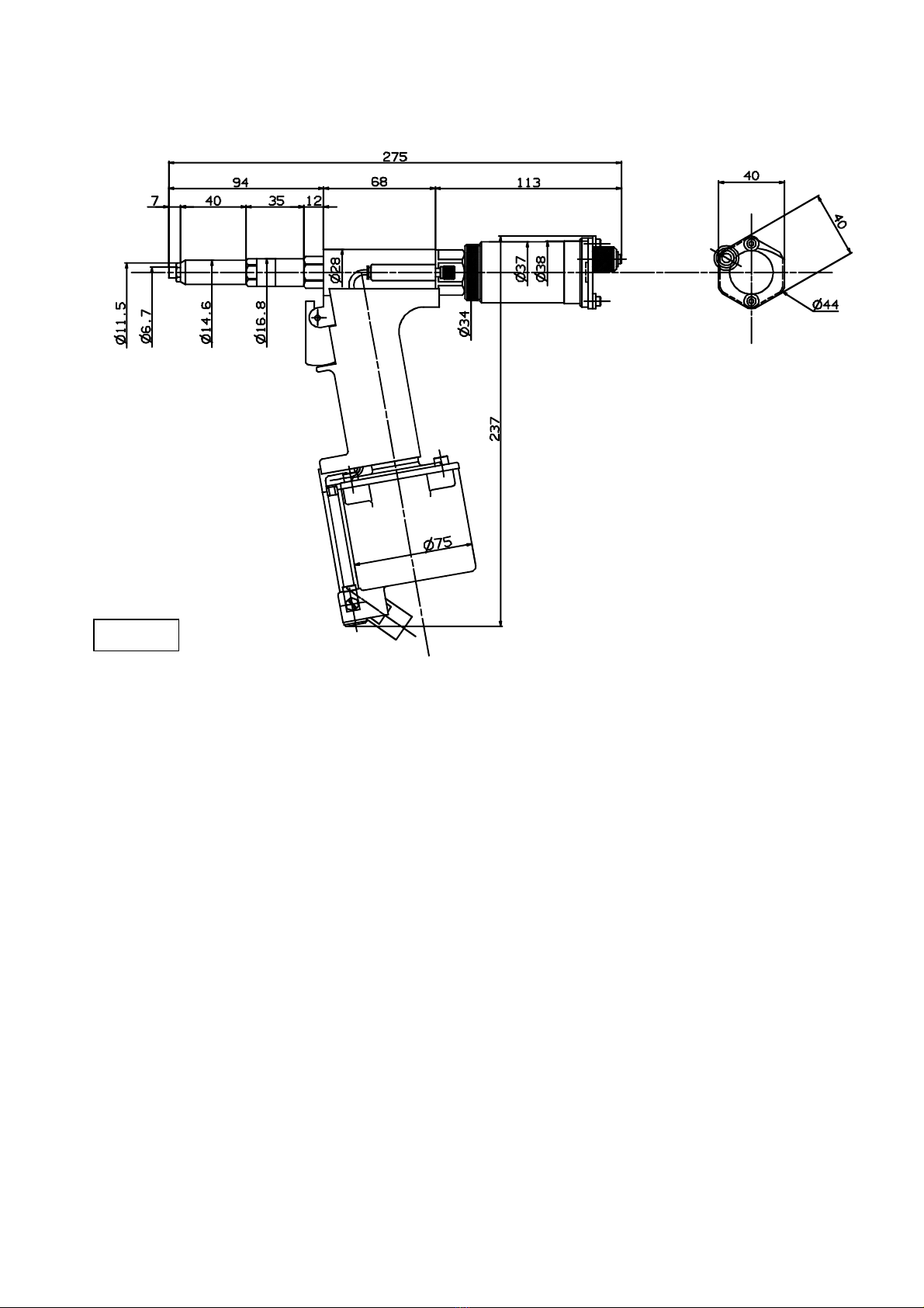
PRL550 0.89 275 237 18.0 0.5〜0.6
2.Nosepiece (Table 2-2)
Use an appropriate nosepiece according to the type and size of rivet.
Using different size nosepiece may cause faultily rivet setting or tool malfunctions.
(Table 2-2) Rivet Nose piece
Rivet dia.
(φmm) Rivet name Mandrel
dia.
(φmm)
Product
No. Hole dia.
(φmm) Remark
3.0 TAP/D(K)30M-BS PAD30M-ABS(HR/CC)
A6D30M-HR/CC SD30M-BS
TAP/D(K)4-BS(SSBS) TAP/D(K)4-SW
TAP/D4-BHM AD4-BS/LF
TCP/D-BS(BSB)
1.83
AD(K)4-ABS TAP/D(K)4-HR
SD(SSD)4-BHM
SD(K)4-BS SSD(K)4-BS(SSBS)
SSD4-SSH
1.93
PRN041 2.2 Std.
Equipment
SD(K)4-HR SSD(K)4-HR(SSHR) 2.10 PRN04K 2.4 Option
AD(K)4 AD4-SSH CD4 1.63 PRN042 1.8 Option
3.2
AD4-AH 1.83 PRN043 2.0 Option
TAP/D(K)5-BS *TAP5-SSBS
TAP/D(K)5-SW
TAP/D5-BHM AD5-BS/LF
TAP/D(K)5-HR
AD5-TL TCP/D5-BSB
2.28
AD(K)5-ABS *SD(K)5-BS 2.41
PRN051 2.7 Accessory
CD5 *AD(K)5 *AD5-SSH 2.18 PRN052 2.4 Option
4.0
AD5-AH 2.28 PRN053 2.5 Option
Mandrel dia.
Body dia.
Stam
p
Hole dia.
* : The air pressure of 0.55MPa or more is necessary.
- 4 -
PRL550
3. Dimensional Drawing
PRL550
- 5 - Fi
g
.3-1

PRL550
4. Preparation for use
(1) Make sure that Nosepiece that suits the rivets used are attached: If incompatible
parts are attached, replace them with those specified to suit the rivets used (see Table
2-2 on P. 4).
(See P.14 for Replacing Nosepiece.)
(2) Attach the coupler (AN500-72) to R-Joint block of rivet tool, to supply compressed air.
Install the air filter and regulator between Compressors and rivet tool, and adjust the
pressure of air supplied to 0.5-0.6 MPa.
Fig. 4-1
A
ir filter
Regulator
Hos
e
Coupler (Socket)
Recommended internal dia.
: at least 6mm
(Recommended)
NITTO KOUKI20SH
20SM
20SF
Compressor
R-Joint
(Rc 1/4)
Coupler (Plug)
AN500-72
NotAttached
Use the hose with the pressure at normal temperature (maximum) of a
t
least 0.7 MPa, and suitable for environment where the tool is used.
(Example: Consider oil resistance, wear resistance, etc.)
WARNING
(3) Confirm whether the shutter shuts. Turn the shutter to the right, and shut in case of
the opening. (see Fig4-2)
(4) The Valve shutter must revolve to the left one-twice, open, and operate MCS.
(see Fig.4-2)
Shutter
Fig.4-2
V
alve shutter
Collector
Operate MCS
Revolve to the left one-twice Shut
When the amount of the opening of th
e
V
alve shutter is insufficient, the mandre
l
might not be able to be collected.
Shut the Valve shutter (Screw in unti
l
stopping), and stop MCS when you do no
t
do rivetting.
*
*
- 6 -

PRL550
- 7 -
5. Precautions for use
(1) Air pressure used
Use the rivet tool with an air pressure of 0.5-0.6 MPa.
If the specified air pressure is exceeded, the tool could break, resulting in an accident
or injury. If the air pressure is lower than that specified, it may not be possible to
setting rivets.
Use the regulator to adjust the air pressure to optimum value. (see P.6)
(2) Using air filter
Moisture or dust contained in compressed air could affect the life of rivet tool: Use an
air filter. (See P.6)
(3) Nosepiece
Use an appropriate nosepiece according to the type and size of rivet.
(see Table 2-2 on P.4)
Using different size nosepiece may cause faultily rivet setting or tool malfunctions.
(4) Hydraulic oil
Use specified hydraulic oil.
Select the hydraulic oil from Table 5-1: Other oil could cause malfunctions.
(Table5-1)specifiedoil
Oil company Name
Idemitsu Kosan Daphne Hydro 68A
Mobil Sekiyu Mobil DTE 26
Cosmo Sekiyu Cosmo Orpheus 68
Esso Sekiyu Telesso 68
Nippon Petroleum FBK R068
Mitsubishi Oil Diamond Lub R068 (N)
Showa Shell Sekiyu Shell Oil C68
(5) Discard mandrels collected in the Collector
Discard mandrels collected in the collector before the accommodation capacity of
collector is not exceeded (Table 6-1 on P.9).
(Note) Exceeding the maximum capacity may damage the MCS or cause mandrels to
become stuck inside the tool.
(6) Plastic parts (Handle front, Handle rear, Collector)
Organic solvent do not adhere to the Handle front, the Handle rear, the collector body,
and the collector cover (These materials are polycarbonates).
Use the soapless soap when washing it.
PRL550
6. How to use the PRL650
- 8 -
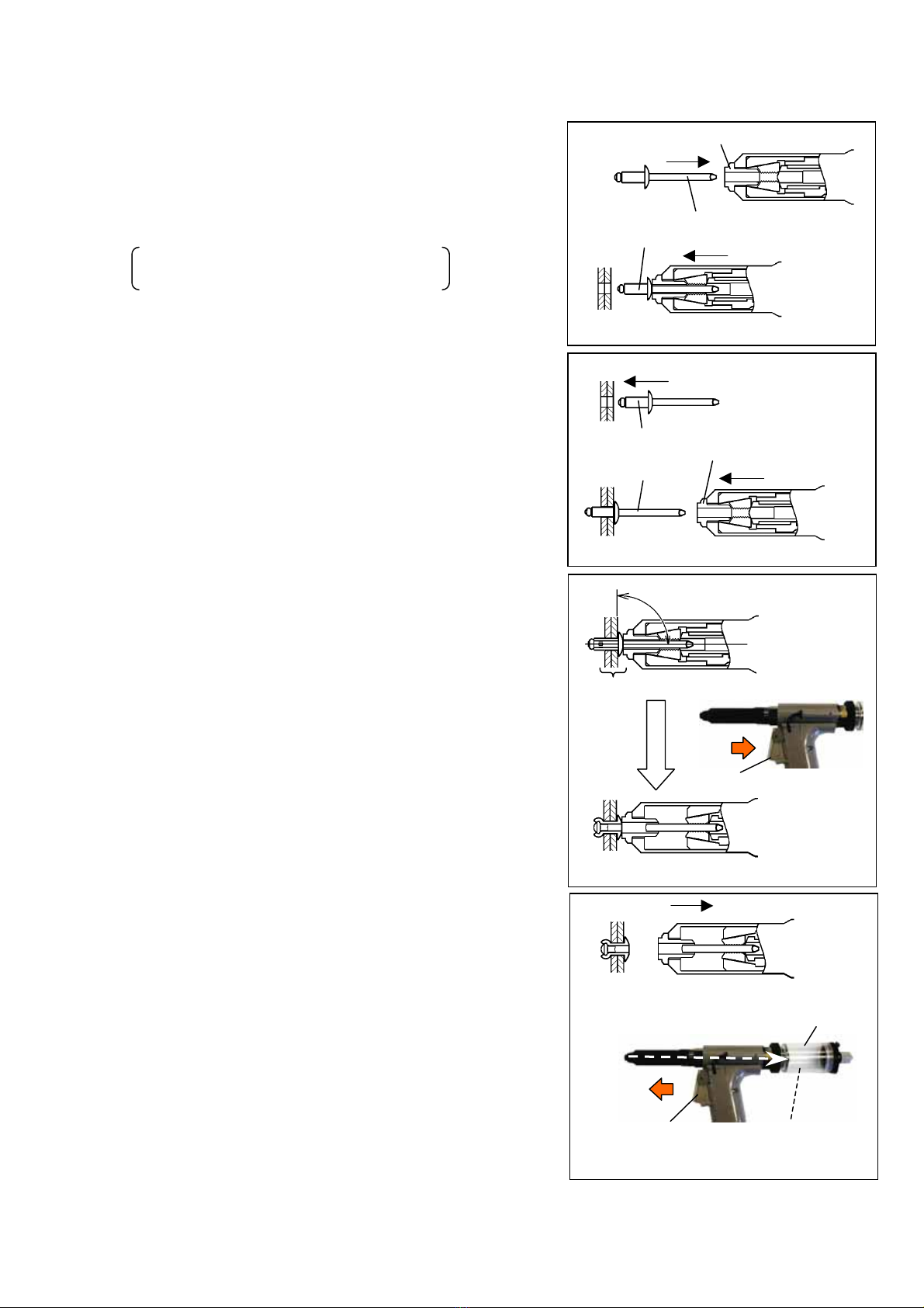
6-1 Setting rivets
(1) Insert mandrel into the nosepiece and attach a
rivet, and then insert the rivet body into the hole
in the lower base metal. (Fig. 6-1)
The rivet is attracted by MCS
into the nosepiece.
Or insert the rivet body into the hole in the lower
base metal, bring the rivet tool to the rivet, and then
insert the mandrel into the nosepiece. (Fig. 6-2)
(2) Push the rivet tool against the base metal at right
angles, and then pull the trigger while the base
metals to be joined and the rivet flange and
nosepiece are in close contact: The mandrel
ruptures and the rivet is set to join base metals.
(Fig. 6-3)
Trigger
Pull
Right angle
Close contac
t
Fig. 6-3
Ruptured mandrel
Trigger
Release
Collector
Base
Metal
Nose
p
iec
e
Body Mandrel
Fig. 6-1
Fig. 6-2
Base metal
Body Nosepiece
Mandrel
Fig. 6-4
(3) Release the rivet tool from the base metal, and then
release the trigger. (Fig. 6-4)
The ruptured mandrel is attracted by MCS, and is
collected in the Collector.
*Discard mandrels collected in the collector before the
accommodation capacity of collector is not exceeded
(Table 6-1 on P.9).
(4) After making sure that the mandrel has
been ejected, proceed with subsequent
joining.
※ See the catalog of pop rivets for selecting rivets and setting diameter of hole in lower base metal.

PRL550
6-2 Discard mandrel
Discard mandrels collected in the collector before the accommodation capacity of Collector
is not exceeded. (Table 6-1)
(Table 6-1) The accommodation capacity of Collector
Nominal dia.
of rivet Mandrel dia. Accommodation capacity
φ3.2 φ1.63
φ1.83
φ1.93 120
φ2.10
φ2.18 100
φ4.0
φ2.28
φ2.41 70
<Method for use>
The Shutter opens when the Shutter is turned to the left with the Grip pulled, and the
mandrel is discarded from this opening.
When setting rivet, turn the Shutter to the right and shut.
(Fig. 6-5)
Turn left
Collector
Pull
Fig. 6-5
- 9 -

PRL550
7. Maintenance and Inspections
(Table 7.1)
No Item Purpose
7-1 Spraying lubricant into the Jaws ・Maintains proper Jaws operation and extends the service life.
7-2 Cleaning the tip parts ・To remove metal particles and prevent slippage of Jaws or being caught
・To prevent early wear on Jaws and Jaws case
7-3 Greasing the Jaw case ・To remove metal particles and prevent slippage of Jaws or being caught
・To prevent early wear on Jaws and Jaws case
7-4 Exchange of Hydraulic oil ・To restore stroke
7-5 Replacing Nosepiece ・To match the rivets used
・Because of damage
7-6 Replacing Jawpusher ・Because of damage
7-7 Replacing Jaws ・To match the rivets used
7-8 Replacing Ejector complete ・Recovery when MCS function has become degraded
7-1. Spraying lubricant into the Jaws
Lubricating and rust-proofing agents (CRC type) should be sprayed into the Nosepie
cehole approximately every 2,000 rivets in order to maintain proper Jaws operation.
Always close the Valve shutter when spraying the Jaws.
(If the Jaws are spraying with the air connected, the lubricating oil will be drawn in
to the MCS and miss the Jaws.)
Manufacturer Product neme
Kure Industries Inc. CRC5-56
Three Bond Inc. 1801B
Musashi Holtz Inc. Holtz Top Oil
MH241
Lesupi Inc. Pikka
(Reference)
Nosepiece
(PRN-□)
Spray oil Fig. 7-1
7-2. Cleaning the tip parts
Clean the tip parts regularly (two or three times per month). After setting 10,000 rivets,
metal powder will adhere to the tip parts causing tool action to deteriorate and the Jaws
to slip or catch. Continuing operation under these conditions will shorten the service life of
the Jaws and other tip parts.
(1) Loosen the Nose housing with a wrench and remove it.
(2) Loosen the Jaw case from the Pulling head with wrentches.
(3) The parts which will come off are shown (Fig. 7-2). Clean these parts and the Nose
housing with kerosene or similar oil. In addition, blow air through the Pulling head and
Nose housing to clean them.
- 10 - Fig 7-2
Nose housing
Jaw case
Pulling hesd
Jaw pusher Mandrel guide
Jaws Jaw pusher spring
PRL550
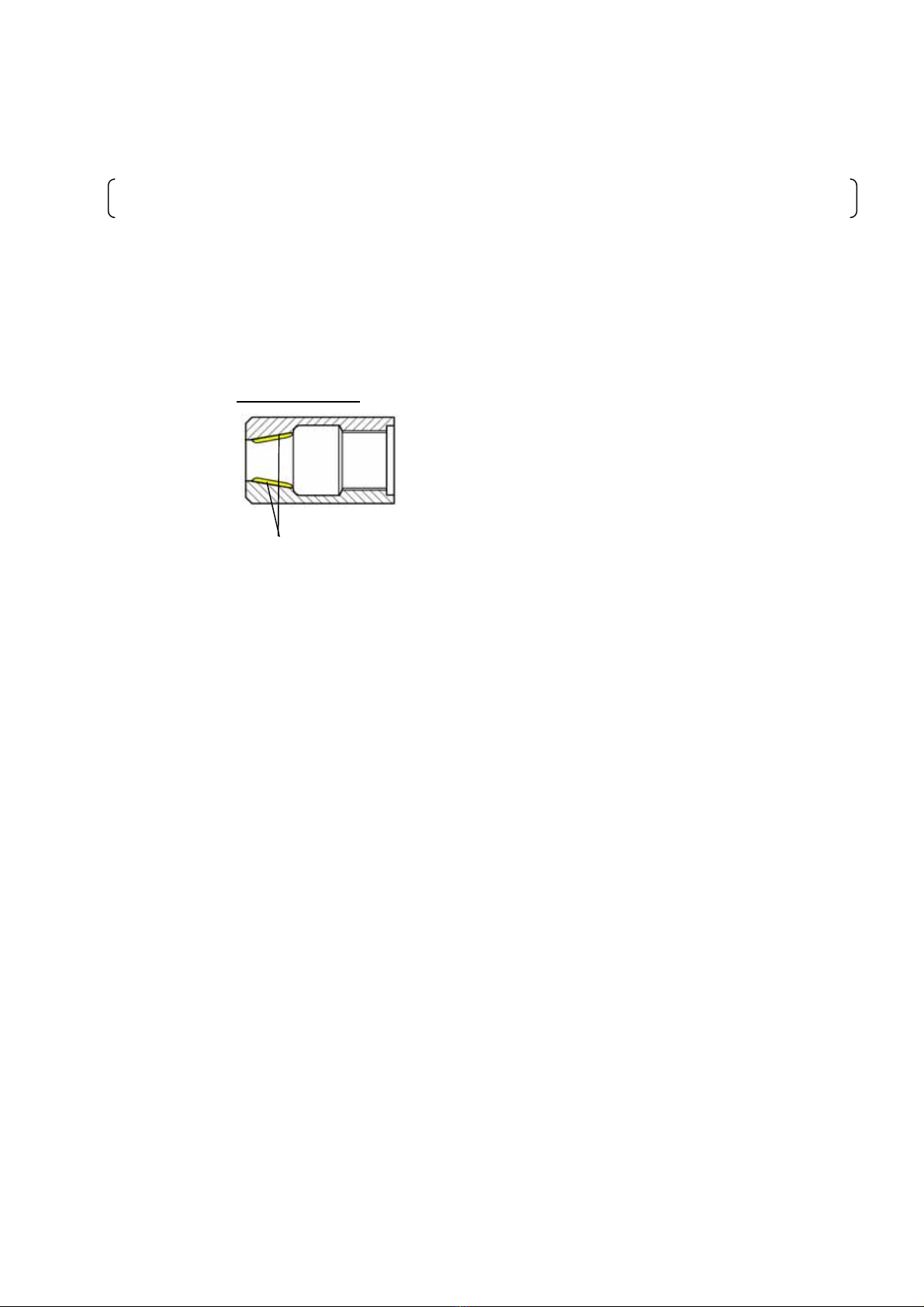
7-3. Greasing the Jaw case
When Jaws slipping or catching occurs earlier in the spraying lublicant into the Jaws,
grease inside of Jaw case.
Catching: After a rivet is setting, the jaw is caught by the jaw case and does not open, and
the mandrel cannot be ejected.
<Procedure>
(1) Clean the tip parts according to P.10 7-2.
(2) Reassemble the parts by the reverse procedure to disassembly. Grease the inside of jaw case (surface
that is in contact with jaw) sufficiently before reassembly (see Fig. 7-3): Molybdenum disulfide type is
recommended.
Jaw case (section)
Grease (2~3mm thick)
Fig. 7-3
- 11 -

PRL550
7-4. Exchange of Hydraulic oil
When hydraulic oil is down and the stroke is low (one trigger operation does not allow
riveting), exchange the hydraulic oil by the following procedure:
If stroke is low immediately after hydraulic oil is exchanged, seal has worn:Ask for repair.
<Procedure>
(1) Cut off supply of compressed air by separating the coupler.
- 12 -
(2) Remove Collector and Nose housing.
(3) Pull out the Tube from Joint while evenly pushing the ring
of open of the Joint by the finger. (Fig. 7-4)
(4) Remove the cap screws (4 pcs) with 4mm hexagonal wrench.
(Fig. 7-5)
Fig.7-6
A
ir piston
assembly
Chamber
(5) Do Chamber up, and remove Chamber.
Pull outAir piston assembly.
Discard Hydraulic oil in the Sleeve. (Fig. 7-6)
Tub
e
Join
t
Fig. 7-5
Cap screw (4pcs)
4mm
Hexagonal wrench
Remov
e
Fig. 7-4
(6) Inject the specified oil (see Table 5-1 on P.7) into the sleeve (hole in which the air piston
assembly was inserted), until the oil surface is the same of Backup ring.
(Fig. 7-7)
H
y
draulic oil
Sleev
e
Sleev
e
Oil surface is sam
e
of Backup ring. Backup ring
Specified oil
Fig. 7-7
PRL550
(7) Loosen Fill screw about 3mm, push and holdAir piston.
The hydraulic oil oozes out from Fill screw, and hold it, until this polluted hydraulic oil
does not come out. (Fig. 7-8)
(8) Pull out Air piston assembly, inject the hydraulic oil again according to (4), and tighten
Fill screw temporarily.
(9) After pushing Air piston assembly, and making the piston move 5-6 times by the hand,
pull outAir piston assembly again, and confirm the oil side. (Fig. 7-9)
Repeat (8) and (9) when the oil side has fallen or air mixes.
Dirty oil
Fill screw
Push and Hold
A
ir piston assembl
y
Making the pisto
n
move 5-6 times by th
e
hand.
Fig. 7-9
Fig. 7-8
(10) After the injection of the hydraulic oil is completed, reassemble Air piston assembly and
Chamber.
Grease inside of Chamber before reassembling.
Assemble it in the reverse order of disassembly.
Fill screw
Remove
Fig.7-10
(11) Loosen Fill screw, and remove an extra hydraulic oil and air (bubble).
Tighten Fill screw after it leaves it until the hydraulic oil does not come out. (Fig.7-10)
- 13 -
(12) Assemble Nose housing and Collector.
*Do not allow any dust or metal particle to enter the hydraulic oil or chamber during
disassembly and reassembly.

PRL550
7-5. Replacing Nosepiece
Use the specified Nosepiece to match the rivets used (see Table 2-2 on P.6).
If Nosepiece is damaged, replace it.
<Procedure>
(1) Use spanner to remove Nosepiece from Nose housing. (Fig. 7-11)
Nosepiece
Nose housing
Remove
Fig. 7-11
(2) Tighten specified Nosepiece to Nose housing firmly.
7-6. Replacing Jawspusher
If Jaw pusher is damaged, replace it.
<Procedure>
Remove used Jaw pusher by the procedure in 7-2 (P.10).
7-7. Replacing Jaws
Use specified jaw to match the rivets used (see Table 2-2 on P.6).
If jaw is damaged or slips immediately after cleaning (teeth are worn), replace it.
<Procedure>
(1) Remove used Jaw by the procedure in 7-2 (P. 10).
(2) Before installing new jaw, clean the tip parts and grease the Jaw case (see 7-2 on P.10
and P.11).
7-8. Replacing Ejector complete
When Ejector nozzle is worn out, or the force is weak, mandrels are not being collected,
and replace Ejector complete.
(Notes)
Check the following before replace Ejector complete: If the applicable defective
phenomenon is found, perform appropriate troubleshooting. (See P.17)
a) Supplied air pressure is low.
b) Mandrel collector is full
c) Mandrel ejection tube is clogged with ruptured mandrels.
d) Jaw pusher and nosepiece are clogged with ruptured mandrels.
If the attraction force is weak after troubleshooting, replace Ejector complete.
- 14 -

PRL550
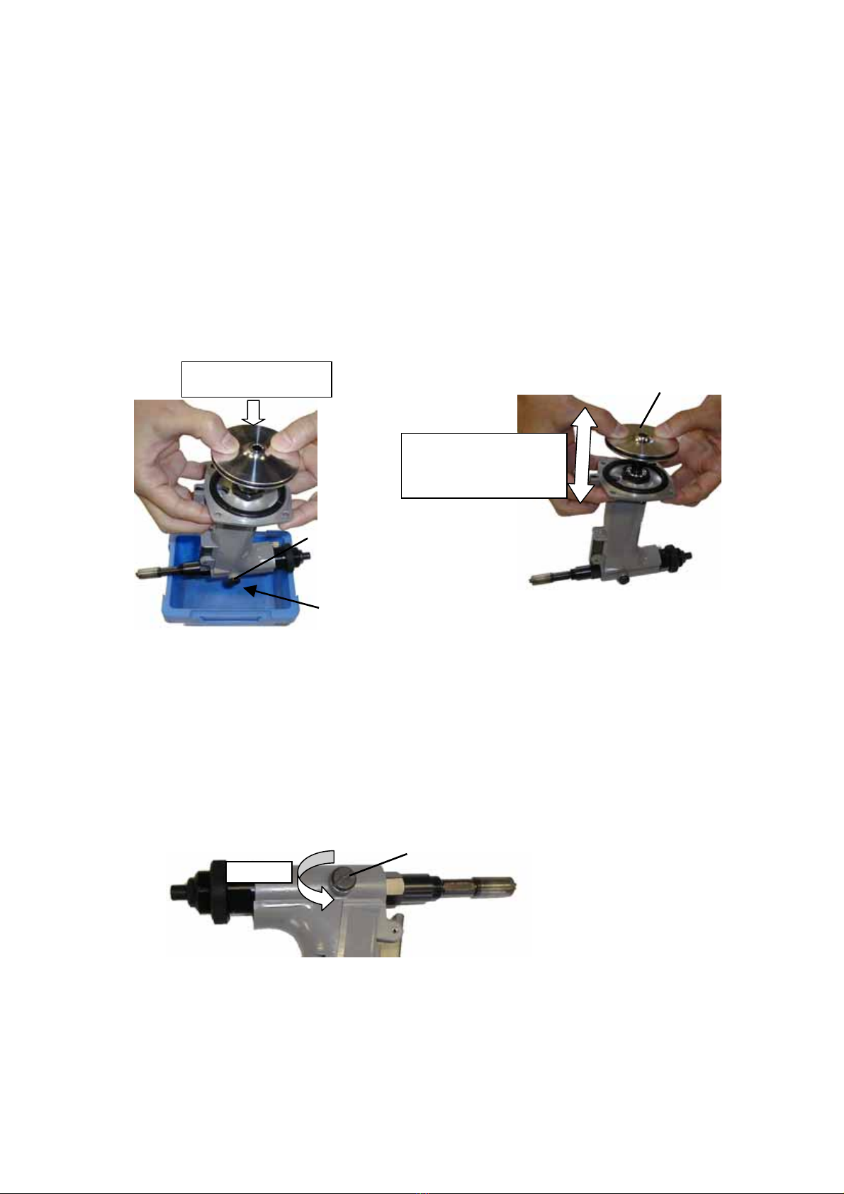
<Procedure>
(1) Cut off supply of compressed air by separating the coupler.
(2) Remove Collector. Collector lock nut is held by the hand, turn Collector in the left, and
remove it. (Fig. 7-12)
Remove
Collector lock nu
t
Collector
Fig. 7-12
(3) Remove Collector lock nut and Valve shutter. (Fig. 7-13)
(4) Remove End cap with wrench. (Fig. 7-14)
Collector lock nut
V
alve shutter
Fig. 7-13
End cap
Return spring
Fig. 7-14
(5) Pull out Ejector complete by the hand. (Fig. 7-15)
(6) Replace it for new Ejector complete.
Spread grease before assembling. (Fig. 7-16)
Fig. 7-15
Ejector complete
Fig. 7-16
Ejector complete
S
p
read
g
rease
WARNING
Do not rivet during this adjustment since compressed air is being supplied.
Also at this time, do not insert a rivet or ruptured mandrel from the nosepiece.
◇If you do, the rivet or ruptured mandrel will pop out because of the compressed air,
which could cause an accident or serious injury (losing eyesight, etc.).
- 15 -

PRL550
- 16 -
8. Troubleshooting
(If you cannot fix the tool after checking the content of this secton, send it to your supplier or
one of our offices for repair.)
Symptom Cause Troubleshooting
1.Parts are incompatible.
Nosepiece is not compatible with rivets
used.
Replace the parts with compatible
ones. (see P.4)
2.Loose parts
Nosepiece, Nose housing, Jaw case are
loose.
Use wrench to securely tighten
them.
3.Damaged parts
Jaw, Nosepiece (section in contact with
Jaw), Jaw pusher or Jaw pusher spring is
damaged.
Replace the damaged parts.
(See P.11)
4.Dirt in Nose housing
Metal particles have accumulated in
Nose housing, which causes defective
opening of Jaw.
Clean nose housing, jaw, etc.
(see P.10)
5.Jaw and jaw case are poorly lubricated.
Defective lubrication causes catching. Clean and grease the point end
parts, such as jaw. (see P.10,11)
6.Excessive hydraulic oil
After hydraulic is replenished, surplus
hydraulic oil and air are not removed.
Loosen the fill-screw and eliminate
surplus hydraulic oil and air.
(see P.13)
Rivet cannot be
inserted into
Nosepiece.
Or mandrel cannot
be ejected after
riveting.
7.Clogging in jaw pusher
Mandrels are clogged in the jaw pusher. Remove the jaw pusher and remove
the clogged objects. (See P.10)
1.Shortage of supplied air pressure. Adjust the supplied air pressure.
(see P.6)
2.The amount which shuts Valve shutter or
opens is insufficient. Open Valve shutter. (see P.6)
3. Ccollector is full of mandrels. Discard the mandrels from
Collector. (see P.9)
4.Mandrels are clogged in Jaw pusher Remove Jaw pusher, and removed
clogged mandrels. (see P.10)
Mandrels cannot
be collected by
MCS
(Attractive force is
weak).
5.Wear-out of Ejector nozzle Replace Ejector complete.(see P.15)
1.Parts are incompatible.
Nosepiece is not compatible with rivets
used.
Replace the parts with compatible
ones. (see P.4, P.14)
2.Shortage of supplied air pressure. Adjust the supplied air pressure.
(see P.6)
3.Slippage of jaw
Metal particles are clogged in jaw teeth
or teeth are worn, and the jaw cannot
catch mandrels, causing slippage.
Clean the jaw.
If fault is not corrected after
cleaning, replace the jaw. (see P.10)
One trigger
operation does not
allow riveting.
4.Stroke is too low
Hydraulic oil is short or air enters,
causing low stroke.
Exchange hydraulic oil. (see P.12)

PRL550
- 17 -
9. Parts List
No. 品番 品名 員数 No. 品番 品名 員数
1 PRN041 Nose piece 1 31 PRL600-64 O-ring P4(U) 2
2 PRL550-01 Jaws 1set 32 PRL600-29A
A
ir tube 4×71 1
6 PRL550-12 Nose housing 1 33 PRL600-28A Joint PCC4M6M 1
7 PRL550-02 Hydraulic piston 1 34 PNT600-80 O-ring S3(1A) 1
8 PRL550-03 Housing adapter 1 35 PL1500i-27A
V
alve shutter 1
9 PRL500-05 Scraper SER9 1 36 PRL600-24 O-ring P5(U) 1
10 PRL500-06A Rod seal case 1 37 PRL600-45A Sleeve upper 1
11 PRL500-07 O-ring P16(U) 2 38 PRL600-46 O-ring P10A(U) 1
12 PRL500-08 BU-ring T2P9(PT) 1 39 PRL500-20 Handle rear spacer 2
13 PRL500-09 Penta seal PS9 1 40 PRL600-48A Handle rear 1
15 PRL500-10 BU-ring T2P16(PT) 1 41 PRL600-70A Handle front 1
16 O-RING-1017 O-ring 1 42 PRL650-14 Sleeve lower 1
17 PRL550-04 Handle upper 1 43 PRL600-80 Pan head screw M3×16 4
18 PRL500-12 Return spring 1 44 PRL600-53B Handle lower 1
19 PRL550-05 End cap 1 45 PRL650-15 Bumper 1
20 PRL500-33 Lock nut 1 46 SA-18 Penta seal PS11.2 1
21 PNT600-60 O-ring S6(1A) 1 47 SA-17 BU-ring T2P11.2(PT) 1
22 PRL550-06 Ejector guide 1 48 PRL550-14 Camber 1
23 PRL550-07 Jaw case 1 49 O-RING-C0630G(1A) O-ring 1
24 PRL550-08/5 Jaw pusher 1 50 PRL650-17
A
ir piston 1
26 SPG5135 Jaw pusher spring 1 51 PRL550-15 Ram 1
27 PRL550-09/5 Mandrel guide 1 52 PRL600-62 Cap 1
28 PRL550-10 Pulling head 1 53 PRL600-63 O-ring S8(1A) 1
29 PRL550-11/5 Ejector 1set 54 PRL600-97
V
alve sprin
g
5082 1
29a PRL650-10/5 Ejector nozzle 1 55 PRL600-65A
V
alve lower 1
29b PRL650-11 Ejector lock 1 56 PRL500-28
Va
lve rod 1
29c PRL550-13/5 Ejector body 1 57 PRL600-68A
V
alve upper 1
30 PNT600-21 Fill screw 1 58 PRM530-43 Spring pin 3×10 2

PRL550
- 18 -
No. 品番品名員数 No. 品番品名員数
59 PRL600-69
V
alve pusher 1 71 PRL500-68A Collector 1set
60 PRL650-19 Sleeve lock nut 1 71a PRL500-36 Collector body 1
61 PRL650-20 Sleeve washer 1 71b PRL500-37A
A
dapter 1
62 PRL600-71 Trigger wire 1 71c PRL500-42A Shutter spacer 2
63 PRL600-72A Trigger 1 71d PSL600CJ-30 Cap screw M3×8 2
64 PRL600-73 Spring pin 3×18 1 71e PRL500-38A Shutter 1
65 PRL600-74 Cap screw M5×12 4 71f PRL500-39A Shutter washer 1
66 PRL500-64A Tube assembly 1set 71g PRL500-40A Pin case 1
66a PRL600-75A Joint PL4M5M 1 71h PRL600-102A Pin case cap 1
66b PRL500-31A Tube 1 71i PRL500-41A Shutter pin 1
66c PRL600-77 Nipple LN-M5-M5 1 71j PRL600-103 E-ring E4 1
66d PRL600-78 Joint LH-FM5-M5 1 71k PRL600-39A Grip 1
67 PRL650-21 RJ-spacer 1 71l PRL600-40A Shutter spring 5113 1
68 PNT600-44A R-joint 1 Accessory
69 PL1500i-22A R-joint adapter 1 PRN051 Nose piece 1
70 PNT600-42 O-ring S9(1A) 2
A
N50
0
-72 Couppler 20PM 1
PRM530-48 Hexagonal wrench 4mm 1
Instruction manual 1
オプション
PRL650-OSV OS-valve 1set
Table of contents
Popular Rivet Tools manuals by other brands


Gesipa
Gesipa taurus 1 Operating manual with spare parts list

Degometal
Degometal GO 3312 SAFETY INSTRUCTIONS AND DIRECTIONS FOR USE

Arconic
Arconic MARSON MP-4V manual

Marson
Marson Integra-Fuse M39075 Operation guide

Milwaukee
Milwaukee M12 BPRT Original instructions

Ingersoll-Rand
Ingersoll-Rand 127 Product information


