INSTRUCTIONS FOR USE
GUARANTEE 4
SAFETY MEASUREMENTS & REQUIREMENTS 4
TOOL IDENTIFICATION 5
MAIN COMPONENTS 5
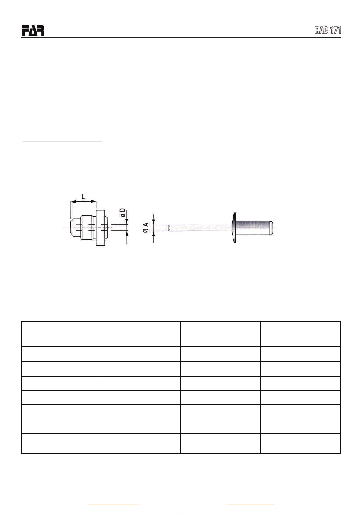
TECHNICAL DATA 5
HOW TO USE YOUR RIVETING TOOL 5
TOPPING UP OIL-DYNAMIC CIRCUIT 6
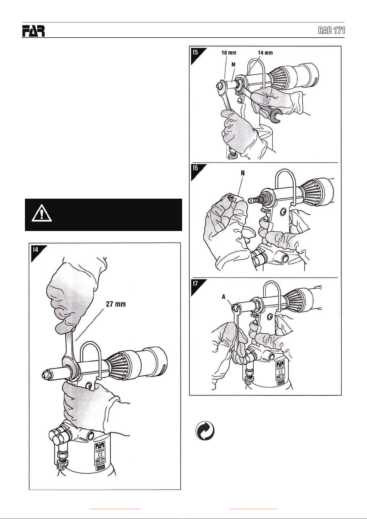
MAINTENANCE & CHANGE OF SIZE 7
DISPOSAL OF THE RIVETING TOOL 7
INDEX
GUARANTEE
FAR riveting tools are covered by a 12-month warranty.
The tool warranty period starts on the date of delivery to
the buyer, as specified in the relevant document. The war-
ranty covers the user/buyer provided that the tool is pur-
chased through an authorized dealer and only if it is used
for the purposes for which it was conceived. The warranty
shall not be valid if the tool is not used or maintained as
specified in the instruction and maintenance handbook. In
the event of defects or failures, FAR S.r.l. shall undertake
solely to repair and/or replace the components it judges to
be faulty.
• The tool needs a thorough six-monthly overhaul.
• Repairing and cleaning operations must be done when
the tool is not fed.
• If it is possible, we suggest a safety balancer.
• If the A-weighted emission sound pressure level is more
than 70 dB (A), you must use some hearing protections
(anti-noise headset, etc.).
• The workbench and the work surface must be always
clean and tidy. The untidy can cause damages to people.
• Do not allow unauthorized persons to use the working
tools.
• Make you sure that the compressed air feeding hoses
have the correct size to be used.
• Do not carry the connected tool by pulling the hose. The
hole must be far from any heating sources or from cutting
parts.
• Keep the tools in good conditions; do not remove either
safety parts or silencers.
• After repairing and/or adjusting, make sure you have al-
ready removed the adjusting spanners.
• Before disconnecting the compressed air hose from the
tool make sure that there is no pressure in the hose.
• These instructions must be carefully followed.
SAFETY MEASURES & REQUIREMENTS
• Read the instructions carefully before using the tool.
• For all maintenance and/o r repairs please contact FAR
s.r.l. authorized service centers and use only original
spare parts. FAR s.r.l. may not be held liable for
damages from defective parts caused by failure to ob-
serve what above mentioned (EEC directive 85/374).
• The tool must be used only by expert workers.
• A protective visor and gloves must be put on when us-
ing the tool.
• Use equipment recommended in the maintenance
chapter to do any maintenance and/or regulation of the
tool.
• For topping up the oil, we suggest using only fluids in
accordance with the features specified in this working
book.
• If any drop of oil touches your skin, you must wash with
water and alkaline soap.
• The tool can be carried and we suggest putting it into its
box after using.
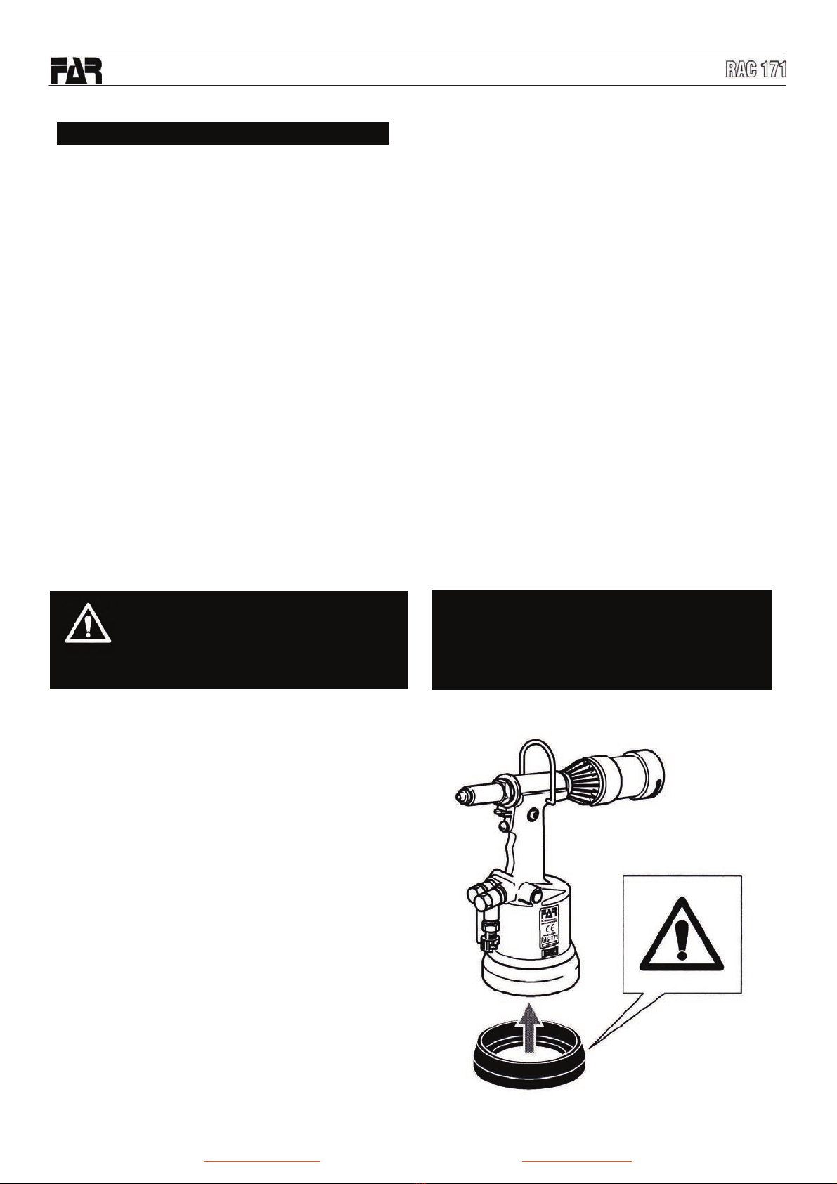
WARNING!
Before using the tool, assemble the protectionbottom sup-
plied with the tool, as indicated in the picture below.
FAR has no responsibility for any damages of the tool,
person or things caused by lack of the protection.
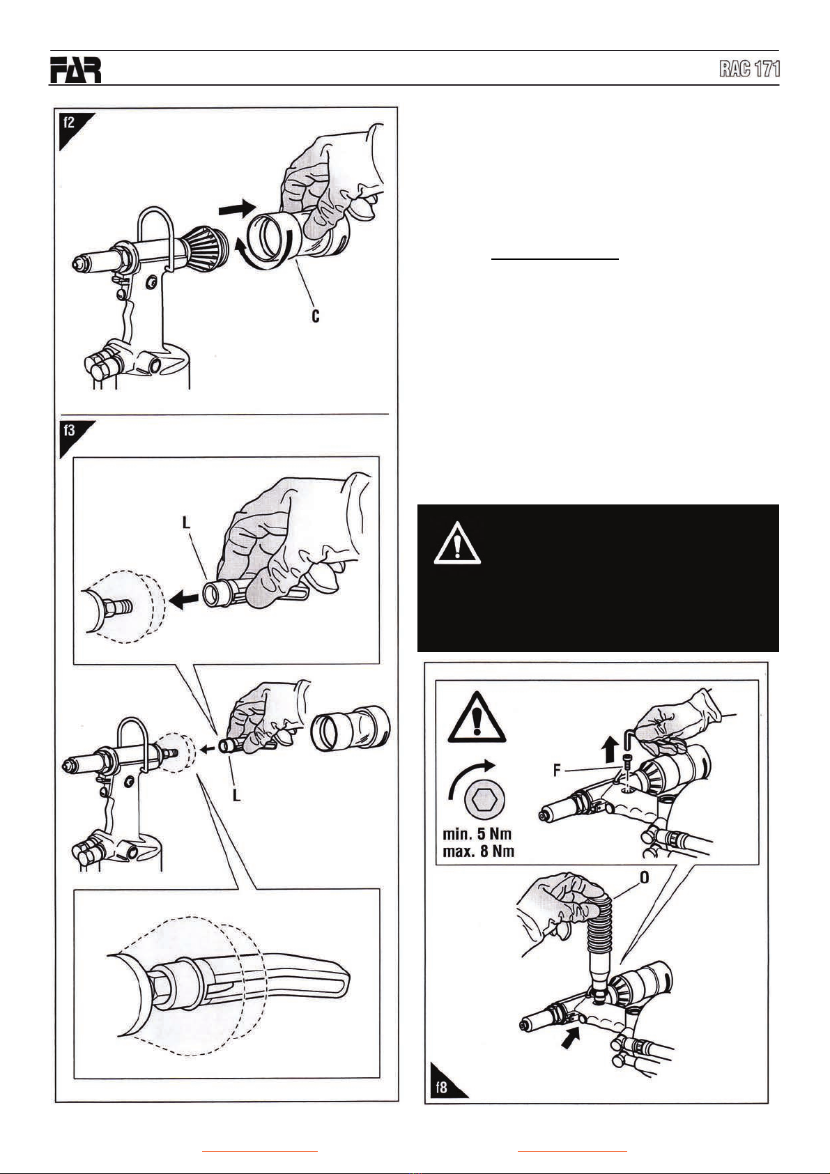
CAUTION!!!
All the operations mustbe done in conformity with
the safety requirements, in order to avoid any
consequence for your and other people’s security
and to allow the best tool work way.