Farfisa 2231Q User manual

- 1 -
Mi 2489/3
2
"
8
/
3
60
3
"
2
/
1
89
2
"
8
/
1
54
IT
SEPARATORE DI MON-
TANTI PER SISTEMA DUO
Il separatore 2231Q consente la crea-
zione di sezioni indipendenti all'interno
di una installazione videocitofonica DUO
permettendo di avere servizi locali senza
impegnare la lineaprincipale condominiale.
Il dispositivo può essere utilizzato per di-
videre l'impianto in blocchi (DUO a Range
Esteso versione PDX2 che prevede la pos-
sibilità di collegare no a 25000 dispositivi
e di gestire centralini di portineria principali
e/o secondari).
Alcuni esempi sono:
- servizi intercomunicanti e/o domotici in
unoopiùappartamenticon/senzaingres-
so secondario;
- collegamento di unapalazzina (con/senza
ingresso secondario) aduno o piùingressi
principali;
- divisione a blocchi dell'impianto (DUO a
Range Esteso) per il collegamento di più
palazzine con/senza ingressi principali/
secondari e con/senza centralini di por-
tineria principali o secondari.
EN
LINE BUFFER FOR DUO
SYSTEM
The buer 2231Q can be used to create
independent sections within the same DUO
videointercom installation, thus allowing to
have local services without engaging the
main common line. This device can also
be used to divide the system into blocks
(DUO Extended Range version PDX2 which
allows to connect up to 25000 devices and
to manage door keeper exchangers either
main or secondary).
A few examples are:
- intercom and/or home automation
services in one or more apartments with/
without a secondary entrance;
- connection of a building (with/without
secondary entrance) to one or more main
entrances;
- division of the system into blocks (DUO
Extended Range) for the connection of
several buildings with/without main or sec-
ondary entrances and with/without main
or secondary door keeper exchangers.
FR
SÉPARATEUR DE MON-
TANTS POURSYSTÈMEDUO
Le séparateur 2231Q permet la création
de sections indépendantes à l’intérieur
d’une installation de vidéophonique DUO
permettant d’avoir des services locaux
sans occuper la ligne principale de la
copropriété. Le dispositif est utile pour
diviser l’installation en blocs (DUO à
Large Range, version PDX2, permettant
de brancher jusqu'à 25000 dispositifs et
de gérer des standards de conciergerie
principaux et/ou secondaires).
Quelques exemples sont:
- services inter-communicants et/ou do-
motiques dans un ou plusieurs apparte-
ments avec/sans entrée secondaire ;
- Raccordement d’un bâtiment (avec/
sans entrée secondaire) à une ou plu-
sieurs entrées principales ;
- Division de l’installation à blocs (DUO
à Range Étendu) pour la connexion de
plusieurs petits immeubles avec/sans
entrées principales/secondaires et avec
/sans standards de conciergerie princi-
paux et/ou secondaires.
ES
SEPARADORDEMONTAN-
TES PARA SISTEMA DUO
El separador 2231Q permite la creación
de secciones independientes dentro de
una instalación por videoporteros DUO,
para tener servicios locales sin ocupar la
línea principal común. El dispositivo puede
usarse para dividir el sistema en bloques
(DUO de Gama Extendida versión PDX2
que prevé la posibilidad de conectar hasta
25000 dispositivos y gestionar centralitas
de conserjería principales y/o secundarias).
Algunos ejemplos son:
- servicios de intercomunicación y/o do-
móticos en uno o varios apartamentos
con o sin entrada secundaria;
- conexión de un edicio (con o sin en-
trada secundaria) a uno o más ingresos
principales;
- división en bloques del sistema (DUO de
Gama Extendida) para conexión de varios
edicios con/sin entradas principales/
secundarias y con/sin centralitas de
conserjería principales o secundarias.
PT
SEPARADORDE MONTAN-
TES PARA SISTEMA DUO
O separador 2231Q consente a criação
de secções independentes no interior
de uma instalação de vídeo porteiro
DUO, permitindo a obtenção de serviços
locais sem empenhar a linha principal
condominial. O dispositivo pode ser
utilizado para dividir a instalaçãoem blocos
(DUOdeAmplitudeEstendidaversãoPDX2
que prevê a possibilidade de conectar
até 25000 dispositivos e gerir centrais de
portaria principais e/ou secundárias).
Alguns exemplos são:
- serviços de intercomunicação e/ou do-
móticas em um ou mais apartamentos
com/sem entrada secundária;
- ligação de edifício (com/sem entrada
secundária) a uma ou mais entradas
principais;
- divisão da instalação em blocos (DUO
de Amplitude Estendida) para a cone-
xão de mais edifícios com/sem entradas
principais/secundárias e com/sem cen-
trais de portaria principais ou secundá-
rias.
DE
TRENNER DER STEIGLEI-
TUNGFÜRDUO-BUSSYSTEM
Der Trenner 2231Q ermöglicht unabhängige
Abschnitte innerhalb einer Installation
einer DUO Videotürsprechanlage für den
Gebrauch von lokale Dienstleistungen ohne
die Hauptleitung zu belegen.
Das Gerät kann eingesetzt werden, um
die Anlage in zwei Blöcke zu unterteilen
(DUO erweiterte Reichweite, Version
PDX2, mit Möglichkeit, bis zu 25.000
Vorrichtungen anzuschließen und Haupt-
sowie Nebenschaltstellen für Portierslogen
zu bedienen).
Einige Beispiele sind:
- Miteinander verbundene Systeme und/
oder Heimautomation in einer oder
mehreren Wohnungen mit/ohne Ne-
beneingang;
- Anschluss eines Wohnhauses (mit/ohne
Nebeneingang) an einen oder mehrere
Haupteingänge;
- in Blöcke unterteilte Anlage (DUO
erweiterte Reichweite), um mehrere
Gebäude mit/ohne Haupt- und
Nebeneingängen sowie mit/ohne Haupt-
und Nebenstellen für Portierslogen
anzuschließen.
Mi 2489/3
ART. 2231Q

Mi 2489/3
- 2 -
B
DV2420
CLM
LM
LM
LM
LM
LM
PA
SE
A
22 12MQ
2221S
22 12MQ
2221S
22 12MQ
2221S
LP
LP
LP
LP
LP
LP
2S220
LOLO
PE (232)
Agorà
Profilo
Matrix
LP
LP
S1
S2
127/230Vac
127/230Vac
127/230Vac
LI
LI
LI
LI
LO
LO
LO
LO
LI
LI
J1=3-4
1
1
2
2
3
3
4
4
2231Q
PEs (231)
PEs (231)
LP
LP
LP
LP
LS
LS
LS
LS
LP
LP
LP
LP
PA
PA
SE
SE
A
A
2S220
2S220
S1
S2
S1
S2
127/230Vac
127/230Vac
B
B
Agorà
Profilo
Matrix
Agorà
Profilo
Matrix
VC CT-
VC CT-1 VC CT-2
FP
FP
Zhero
myLogicOne
Echos
Exhito
Zhero
myLogicOne
Echos
Exhito
LM
LM
A1
GN
LM
LM
A1
GN
LM
LM
A1
GN
E
E
J1=1-2=100
11223344
3-4 1-2=100
1234
1-2=100
127/230Vac
2231Q
IT
Esempi installativi
EN
Examples of installation
FR
Exemples de installation
ES
Ejemplos de conexión
PT
Exemplos de ligação
DE
Anschlussbeispiele
PA = Pulsante apriporta (opzionale)
Door release push-button (optional)
Bouton-poussoir ouvre porte (optionnel)
Pulsador abrepuerta (opcional)
Botão para abrir a porta (opcional)
Türönertaste (Zusatztaste)
SE = Serratura elettrica (12Vca-1A max.)
Electric door lock (12VAC-1A max)
Gâche électrique (12Vca-1A max)
Cerradura eléctrica (12Vca-1A máx.)
Fechadura eléctrica (12Vca-1A max)
elektrisches Türschloss (12Vca-1A max)
FP = Pulsante di piano (opzionale)
Door release push-button (optional)
Bouton-poussoir de palier (optionnel)
Pulsador de piso (opcional)
Botão de patamar (opcional)
Treppenhausruftaste (Zusatztaste)
PE = Posto esterno comune e secondario (s)
Common and secondary (s) door station
Plaque de rue commune et secondaire (s)
Placa de calle común y secundaria (s)
Botoneira comum e secundária (s)
Gemeinsamen Eingang und Sekundär (s)
VC - CT = Videocitofono o citofono
Videointercom or intercom
Moniteur ou interphone
Monitor o teléfono
Videoporteiro ou telefone
Videosprechgerät oder Haustelefon

- 3 -
Mi 2489/3
Dati tecnici
Alimentazione dalla linea
Assorbimento (LI-LO): 10mA
Assorbimento (LM-LM): - a riposo 40mA
- con carico 70mA
Contenitore: DIN 3 moduli A
Temperatura di funzionamento: 0° ÷ +50°C
Massima umidità ammissibile: 90% RH
Fissabile su guida DIN o a muro con 2 tasselli
ad espansione
Morsetti
LM - LM Ingresso alimentazione di linea
LI - LI Ingresso della linea DUO principale
LO - LO Uscita della linea DUO principale
LP - LP Ingressodapostoesternosecondario
LS - LS Uscita della linea DUO secondaria
Technical features
Power supply from the line
Current (LI-LO): 10mA
Current (LM-LM): - stand-by 40mA
- operating 70mA
Housing: 3 module A DIN
Operating temperature: 0° ÷ +50°C
Maximum humidity acceptable: 90% RH
Fits on DIN bar or with 2 expansion plugs
Terminals
LM - LM Line power supply input
LI - LI Main DUO line input
LO - LO Main DUO line output
LP - LP Input from secondary door station
LS – LS Secondary DUO line output
Données techniques
Alimentation de la ligne
Absorption (LI-LO): 10mA
Absorption (LM-LM): - à repos 40mA
- pendant le charge 70mA
Boîtier: DIN 3 modules A
Température de fonctionnement: 0° ÷ +50°C
Humidité maximale admissible: 90% RH
Fixation sur rail DIN ou dans coret mural avec
2 tasseaux à expansion.
Bornes
LM - LM Entrée d’alimentation de ligne
LI - LI Entrée de la ligne DUO principale
LO - LO Sortie de la ligne DUO principale
LP - LP Entréedepuisplaquederuesecondaire
LS – LS Sortie de la ligne DUO secondaire
Datos técnicos
Alimentación de la línea
Consumo (LI-LO): 10mA
Consumo (LM-LM): - en reposo 40mA
- con carga 70mA
Recipiente: DIN 3 módulos A
Temperatura de funcionamiento: 0°÷+50°C
Máxima humedad permitida: 90% RH
Fijación en carril DIN o tacos a expansión
Bornes
LM - LM Entrada de alimentación de línea
LI - LI Entrada de la línea DUO principal
LO - LO Salida de la línea DUO principal
LP - LP Entrada para placa de calle secundaria
LS – LS Salida de la línea DUO secundaria
Dados técnicos
Alimentação da linha
Absorção (LI-LO): 10mA
Absorção (LM-LM): - em repouso 40mA
- com carga 70mA
Recipiente: DIN 3 módulos A
Temperatura de funcionamento: 0° ÷ +50°C
Máxima umidade permitida: 90% RH
Fixável em barra DIN ou com parafusos a
expansão
Terminais
LM - LM Entrada de alimentação de linha
LI - LI Entrada da linha DUO principal
LO - LO Saída da linha DUO principal
LP - LP Entrada pela botoneira secundária
LS – LS Saída da linha DUO secundária
Technische Daten
Stromversorgung über Ltg.
Stromaufnahme (LI-LO): 10mA
Stromaufnahme (LM-LM): - im Ruhe 40mA
- im Betrieb 70mA
Gehäuse: DIN 3 Module A
Betriebstemperatur: 0° ÷ +50°C
max. zulässige Feuchtigkeit: 90% RH
Befestigung auf DIN-Schiene oder an der
Mauer mittels 2 Spreizdübeln
Anschlussklemmen
LM - LM Eingang Versorgungslinie
LI - LI Eingang der Hauptlinie DUO
LO - LO Ausgang der Hauptlinie DUO
LP - LP Eingang der sekundären Außenstelle
LS – LS Ausgang der Nebenlinie DUO
IT
Tabella delle distanze massime garantite
EN
Table of the maximum permitted distances
FR
Tableau des distances maximales garanties
ES
Tabla de las distancias máximas garantizadas
PT
Tabela das distâncias máximas garantidas
DE
Tabelle der garantierten maximale Kabellängen
Tratta Cavo Farsa 2302 Cavo telefonico Cavo CAT5
Section Farsa 2302 cable Twisted cable CAT5 cable
Tronçon Câble Farsa 2302 Câble torsadé Câble CAT5
Tramo Cable Farsa 2302 Cable trenzado Cable CAT5
Trecho Cabo Farsa 2302 Cabo trançado Cabo CAT5
Strecke Farsa 2302 Kabel gedrilltes Kabel Kabel CAT5
2x1mm² - AWG17 2x0,32mm² - AWG22 2x0,2mm² - AWG24
A50 m - 164 ft 10 m - 33 ft 5 m - 17 ft
B150 m - 328 ft 150 m - 328 ft 150 m - 328 ft
C150 m - 328 ft 150 m - 328 ft 150 m - 328 ft
E * 30 m - 164 ft 10 m - 33 ft 5 m - 17 ft
* La somma di tutte le tratte "E" non deve superare i 300 metri.
The sum of all sections "E" must not exceed 300 meters.
La somme de tous les tronçons “E” ne doit pas dépasser 300 mètres.
El total de todos los tramos “E” no puede ser superior a los 300 metros.
A soma de todos os trechos “E” não deve superar 300 metros.
Die Summe aller "E" darf 300 Meter nicht überschreiten.

Mi 2489/3
- 4 -
1234
LP LP LS LS
LM
LM
LI
LI
LO
LO
1234
MADE IN ITALY
IN: LI - LO Line 0.4W
IN: LM Line max 2.5W
2231Q
1234
1234
1234
Morsettiera per LP-LS-LM
Terminal board for LP-LS-LM
Connecteurs pour LP-LS-LM
Conectores para LP-LS-LM
Steckverbinder für LP-LS-LM
Posizione dei connettori e relativa funzione
Position of connectors and related function
Position des connecteurs avec leur fonction
Posición de los conectores y relativa función
Posição dos conectores e relativa função
Position der Steckverbinder und deren Funktion
Connettori J2 e J3 (solo per servizio)
Connectors J2 and J3 (service only)
Connecteurs J2 et J3 (seul entretien)
Conectores J2 y J3 (solo servicio)
Conectores J2 e J3 (somenteassistência)
Steckverbinder J2 und J3 (nur Service)
Micro-interruttori di programmazione.
Microswitches for programming.
Micro-interrupteurspourla programmation.
Micro-interruptores para la programación.
Micro-interruptores para a programação.
DIP-Schalter für die Programmierung.
LED indicazione modo operativo
- Lampeggio lento: normale;
- lampeggio veloce: programmazione.
LED showing operating mode
- Slow ashing : normal;
- fast ashing: programming.
LED montrant le mode de fonctionnement
- Clignotement lent: normal;
- clignotement rapide: programmation.
LED que muestra el modo de funcionamiento
- Parpadeo lento: normal;
- parpadeo rápido: programación.
LED que mostra o modo de funcionamento
- Piscando lento: normal;
- piscando rápido: programação.
LED zeigt Betriebsmodus
- Blinkt langsam: Normal;
- Blinkt schnell: Programmierung.
Morsettiera per LO-LI
Terminal board for LO-LI
Connecteurs pour LO-LI
Conectores para LO-LI
Steckverbinder für LO-LI
Ponticello per adattare l'impedenza del segnale video.
Jumper to adjust the impedance of the video signal.
Petit pont pour adapter l’impédance du signal vidéo.
Puentecillo para adaptar la impedancia de la señal de video.
Jumper para adaptação da impedância do sinal de vídeo.
Jumper zur Impedanzregulierung des Videosignals.
2-3
chiusura 15W
termination 15W
fermeture 15W
cierre 15W
fechar 15W
Abschluss 15W
3-4
linea aperta
opend line
ligne ouverte
línea abierta
linha aberta
oene Ltg.
1-2
chiusura 100W (di fabbrica)
termination 100W (default)
fermeture 100W(d'usine)
cierre 100W (de fábrica)
fechar 100W (de fábrica)
Abschluss 100W (ab Werk)

- 5 -
Mi 2489/3
EN
PROGRAMMING
Preliminary notes
-
To manage videointercom or intercom
addresses connected to the lines LS are
available 10 numerical intervals (F1÷F10).
In each numerical interval can be stored the
address of a single device or the rst and
the last address of a group of intercoms/
videointercoms, with sequential addresses,
related to the same line.
For example if in the numerical interval F1
is stored the address 100, on the line LS
only the calls addressed to the intercom/
videointercom 100 is delivered. Vice-versa if
on the same numerical interval F1 are stored
the addresses 100 and 120, on the line LS
are delivered the call addressed to all the
intercoms/videointercoms whose address
is between 100 and 120.
- To enable the secondary door station ,
if present in the riser, you need to store,
in one of the 10 numerical intervals, the
address of the door station connected to
terminals LP. Use the other numerical
intervals to store the addresses of any
additional door stations connected to the
LP terminals.
-Attention: if during the programming
some error are made or if later it is nec-
essary to modify some addresses al-
ready stored in the memory of the buer
art.2231Q, it is necessary to erase the
whole memory of the device executing
the “memory erasing“ procedure and than
reprogramming completely the device.
Programmingthe numerical intervals
To program the numerical intervals F1÷F10
it is necessary:
1) select the numerical interval to be
programmed, positioning the micro
switches of SW1 according to the
instructions provided in table 1 on page
9; red LED ashes quickly.
For example, to program the interval F1,
set to ON micro switch 1 of
SW1 leaving OFF micro
switches 2, 3 and 4;
2) store the address of the
external door station or internal station
by following the procedure described
here below.
-Videointercom Zhero,myLogic:press
the button .
- Videointercom Echos, Exhito,
Compact: press the button
- Intercom Exhito,Compact: pick up the
handset, press the button , hang up
the handset
- Make a call, from secondary door
stations.
In case you wish to program a group of
addresses, store the address with the
lowest value rst.
If the nal group address also has to be
programmed in the interval, continue
with step 3; if, on the other hand, only
ON
1234
IT
PROGRAMMAZIONE
Informazioni preliminari
- Per la gestione degli indirizzi dei
videocitofoni o citofoni collegati
sulla linea LS sono disponibili 10 fasce
numeriche (F1÷F10). In ciascuna fascia
numerica può essere memorizzato
l’indirizzo di un singolo dispositivo oppure
il primo e l’ultimo indirizzo di un gruppo
di citofoni/videocitofoni, con indirizzi
sequenziali, che fanno capo alla stessa
linea.
Per esempio, se nella fascia F1 si
memorizza solo l’indirizzo 100, su LS
saranno inoltrate le chiamate indirizzate
al solo citofono/videocitofono 100; se
invece nella stessa fascia numerica F1
si memorizzano i numeri 100 e 120, sulla
linea LS saranno inoltrate le chiamate
indirizzate a tutti i citofoni/videocitofoni
che hanno indirizzo compreso tra 100 e
120.
- Perabilitare il postoesternosecondario,
se presente nella colonna montante, oc-
corre memorizzare, in una delle 10 fasce
numeriche, l'indirizzo del posto esterno
collegato ai morsetti LP. Utilizzare altre
fasce numeriche per la memorizzazione
degli indirizzi di eventuali ulteriori posti
esterni connessi ai morsetti LP.
-Attenzione: se nel corso della
programma-zione si commette un errore
o se in un secondo momento si vogliono
modicare gli indirizzi memorizzati nel
separatore, è necessario cancellare tutta
la memoria del dispositivo eseguendo
la procedura di cancellazione memoria e
quindi ri-programmare completamente il
dispositivo.
Programmazione fasce numeriche
Per la programmazione delle fasce
numeriche F1÷F10, occorre:
1) selezionare la fascia numerica
posizionando i microinterruttori di SW1
secondo le indicazioni della tabella 1
di pagina 9; il LED rosso lampeggia
velocemente.
Per esempio per programmare la fascia
F1, posizionare in ON il
microinterruttore 1 di SW1
lasciando in OFF i
microinterruttori 2, 3 e 4;
2) memorizzare l'indirizzodel posto esterno
o posto interno seguendo la procedura
riportata di seguito.
- Dal videocitofono Zhero emyLogic,
premere il tasto
- Dal videocitofono Echos, Exhito e
Compact, premere il tasto .
- Dal citofono Exhito e Compact
sollevare il microtelefono, premere il
tasto e riporre il microtelefono.
-Dai postiesternisecondari, eettuare
una chiamata.
Nel caso si voglia programmare un
gruppo di indirizzi, memorizzare per
ON
1234
FR
PROGRAMMATION
Informations préliminaires
- Pour la gestion des adresses des
moniteurs ou interphones branchés
sur la ligne LS, 10 tranches numériques
(F1÷F10) sont disponibles. Dans chaque
tranche numérique, on peut mémoriser
l’adresse d’un seul dispositif ou bien la
première et la dernière adresse d’un
groupe deinterphones/vidéophones, avec
adresses séquentielles, qui sont à la tête
de la même ligne.
Par exemple, si dans la tranche F1, on
mémorise uniquement l’adresse 100,
les appels adressés uniquement au
interphone/vidéophone 100 sera passé
sur LS; si en revanche on mémorise les
numéros 100 et 120 sur la tranche F1, les
appels adressés à tous les interphones/
vidéophonesquiontuneadressecomprise
entre 100 et 120 sera passé sur la ligne
LS.
- Pouractiver laplaquede ruesecondaire,
si présente sur la colonne montante, il
faut mémoriser sur l’une des 10 plages
numériques, l’adresse de la plaque de rue
raccordéeauxbornes LP. Utiliser d’autres
plages numériques pour la mémorisation
des adresses des éventuelles plaques
de rue supplémentaires connectées aux
bornes LP.
-Attention:siaucoursdelaprogrammation,
on commet une erreur ou si, dans
un second temps, on veut modier
les adresses mémorisées dans le
séparateur, il faut effacer toute la
mémoire du dispositif en eectuant la
procédure d’eacement mémoire et donc
reprogrammer complètement le dispositif.
Programmationtranchesnumériques
Pour la programmation des tranches
numériques F1÷F10, il faut:
1) sélectionner la plage numérique
à programmer en positionnant les
micro-interrupteurs de SW1 selon les
indications du tableau 1 de la page 9;
la LED rouge clignote rapidement.
Par exemple, pour programmer la plage
F1, positionner sur ON le
microinterrupteur 1 de SW1
en laissant sur OFF les
microinterrupteurs 2, 3 et 4;
2) mémoriser l’adresse de la
plaque de rue ou du poste interne
en suivant la procédure reportée ci-
dessous.
- Par le vidéophone Zhero et myLogic,
appuyer sur la touche
- Par le vidéophone Echos, Exhito et
Compact, appuyer sur la touche .
- Par le interphone Exhito et Compact,
soulever le combiné, appuyer sur la
touche , reposer le combiné.
-Depuislesplaquesderuesecondaires,
eectuer un appel.
Si l’on souhaite programmer un groupe
ON
1234

Mi 2489/3
- 6 -
primo l'indirizzo con valore più basso.
Se nella fascia si deve programmare
anche l'indirizzo finale del gruppo
proseguire con il punto 3; se invece deve
essere programmato un solo indirizzo
passare al punto 4.
Note.
- La corretta memorizzazione è indicata
dallo spegnimento per un secondo
e successiva accensione in modo
lampeggiante del LED del separatore.
- Eventuali segnali acustici udibili in questa
fase non rilevano alcuna anomalia nella
programmazione.
3) Dal posto interno, avente l'indirizzo
utente con valore più alto, memorizzare
l'indirizzo seguendo la procedura del
modello scelto. Il separatore acquisisce
l’indirizzo dell'ultimo posto interno
appartenente al gruppo consentendo a
tutti gli interni programmati nella fascia
F1 di connettersi alla linea LS.
4) Riportare in OFF il microinterruttore 1di
SW1. Conquesta operazionesi conclude
la fase di programmazione della fascia
F1.
5) Se richiesto, proseguirein modo analogo
per la programmazione delle altre 9
fasce numeriche ripetendo i punti da
1 a 4 con l’avvertenza di spostare i
microinterruttori di SW1 in accordo con
la fascia che si intende programmare
(vedi tabella 1 di pagina 9).
6) Perusciredallaprogrammazioneoccorre
riportare tutti i microinterruttori di SW1
in posizione OFF; il LED rosso ritorna a
lampeggiare lentamente.
7) Vericare il corretto funzionamento dei
posti esterni e dei citofoni/videocitofoni
collegati alla linea LS dell'art.2231Q.
Cancellazione della memoria
Per cancellare i dati inseriti nella memoria
del dispositivo, occorre:
- posizionare in ON i microinterruttori 1, 2
e 4e lasciare in OFF il microin-
terruttore 3di SW1; il led rosso
inizia a lampeggiare veloce-
mente
- attendere circa 4 secondi; il led rosso
rimane acceso in modo continuo;
- entro 4 secondi portare in ON il microin-
terruttore 3; il led si spegne per
circa 2 secondi, poi, ritorna a
lampeggiare velocemente;
- tutti i dati memorizzati nel dispositivo sono
stati cancellati;
- riportare in OFF tutti i microinterruttori; il
LEDrossoritornaalampeggiare
lentamente.
ON
1234
ON
1234
ON
1234
one address needs to be programmed,
move on to step 4.
Notes.
- Proper storage is indicated by the buer
LED turning o for one second and then
turning back on in ashing mode.
- Possible audio noise signals in this
phase don't notice any anomaly in the
programming.
3) From the internal station, having the user
address with the highest value, store the
address following the procedure of the
selected model. The device acquires
the address of the last internal station
belonging to the group, allowing all the
extensions programmed in interval F1
to connect to the LS line.
4) Set OFF the microswitch 1 of SW1. This
operation ends the programming phase
of the numerical interval F1
5) If required, proceed in a similar way to
program the other 9numerical intervals
repeating the instructions reported on
points from 1 to 4 and paying attention
to set properly the microswitches of SW1
according to the numerical interval to be
programmed (see table 1 on page 9).
6) Set OFF all the microswitches of SW1
and exit the programming mode; red
LED comes back ashing slowly
7) Verify the correct operations of door
stations and of intercoms/video-
intercoms connected to line LS of the
art.2231Q.
Memory erasing
To erase all the data stored in the memory
of the device it is necessary:
- set ON microswitches 1,2 and 4 of SW1
and leave OFF the microswitch
3 of SW1; red LED ashes
quickly
- wait for about 4 seconds; red LED lights
up continuously;
- within 4 seconds set ON the microswitch
3; red LED turns OFF for about
2 seconds and than starts
again flashing quickly;
- at this stage all data have been erased;
- set OFF all the SW1 micro-switches; red
LED comes back flashing
slowly.
ON
1234
ON
1234
ON
1234
d’adresses, mémoriserd’abord l’adresse
ayant la valeur la plus basse.
Sidanslaplagehoraireilfautprogrammer
également l’adresse nale du groupe,
poursuivreaveclepoint3; si au contraire
une seuleadresse doitêtre programmée,
passer au point 4.
Remarques.
- La mémorisation correcte est indiquéepar
l’arrêt qui dure 1 seconde et la mise en
marche successive en mode clignotant
de la LED du séparateur.
- D’éventuels signaux acoustiquesaudibles
durant cette phase n’indiquent pas
d’anomalie dans la programmation.
3) À partir du poste interne, en ayant
l’adresse de l’utilisateur avec une valeur
plus haute, mémoriser l’adresse en
suivant la procédure du modèle choisi.
Le dispositif prend l’adresse du dernier
poste interne appartenant au groupe
en permettant à tous les internes
programmés sur la plage F1 de se
connecter à la ligne LS.
4) Ramenersur OFF lemicro-interrupteur1
de SW1. Avec cette opération, la phase
de programmation de la tranche F1 est
terminée.
5) Si demandé, eectuer de façon analogue
pour la programmation des 9 autres
tranches numériques en répétant
les points de 1 à 4 en ayant soin de
déplacer lesmicro-interrupteurs de SW1
en accord avec la tranche que l’on veut
programmer (voir tableau 1 de la page
9);
6) Ramener tous les micro-interrupteurs
de SW1 en position OFF; la LED rouge
recommence à clignoter lentement;
7) vérifier le fonctionnement correct
des plaques de rue et interphones/
vidéophones au ligne LSdel'art.2231Q.
Eacement de la mémoire
Pour eacer les données entrées dans la
mémoire du dispositif, il faut:
- amener les micro-interrupteurs 1, 2et 4
de SW1 sur ON et laisser sur
OFF le microinterrupteur 3de
SW1; la LED rouge clignote
rapidement.
- attendre environ 4 secondes;la LEDrouge
reste allumée de façon continue;
- dans les 4 secondes, amener sur ON le
micro-interrupteur 3; la LED
s’éteint pendant environ 2
secondes, puis recommence
à clignoter rapidement;
- toutes les données mémorisées dans le
dispositif ont été eacées;
- ramener sur OFF tous les micro-
interrupteurs; la LED rouge
recommence à clignoter
lentement.
ON
1234
ON
1234
ON
1234

- 7 -
Mi 2489/3
ES
PROGRAMACIÓN
Informaciones preliminares
- Para la gestión de las direcciones de los
videoporteros o teléfonos conectados
a la línea LS hay 10 bandas numéricas
disponibles (F1÷F10). En cada banda
numérica es posible memorizar la
dirección de un solo dispositivo o la
primera y la última dirección de un grupo de
teléfonos/videoporteros, con direcciones
secuenciales, que pertenecen a la misma
línea.
Porejemplo, si en la banda F1 se memoriza
solamente la dirección 100, en la L1 se
reenviará las llamadas direccionadas
solamente al videoportero/teléfono 100;
en cambio si en la misma banda numérica
F1 se memorizan los números 100 y 120,
en la línea LS se reenviará las llamadas
direccionadas a todos los videoporteros/
teléfonos cuya dirección está comprendida
entre 100 y 120.
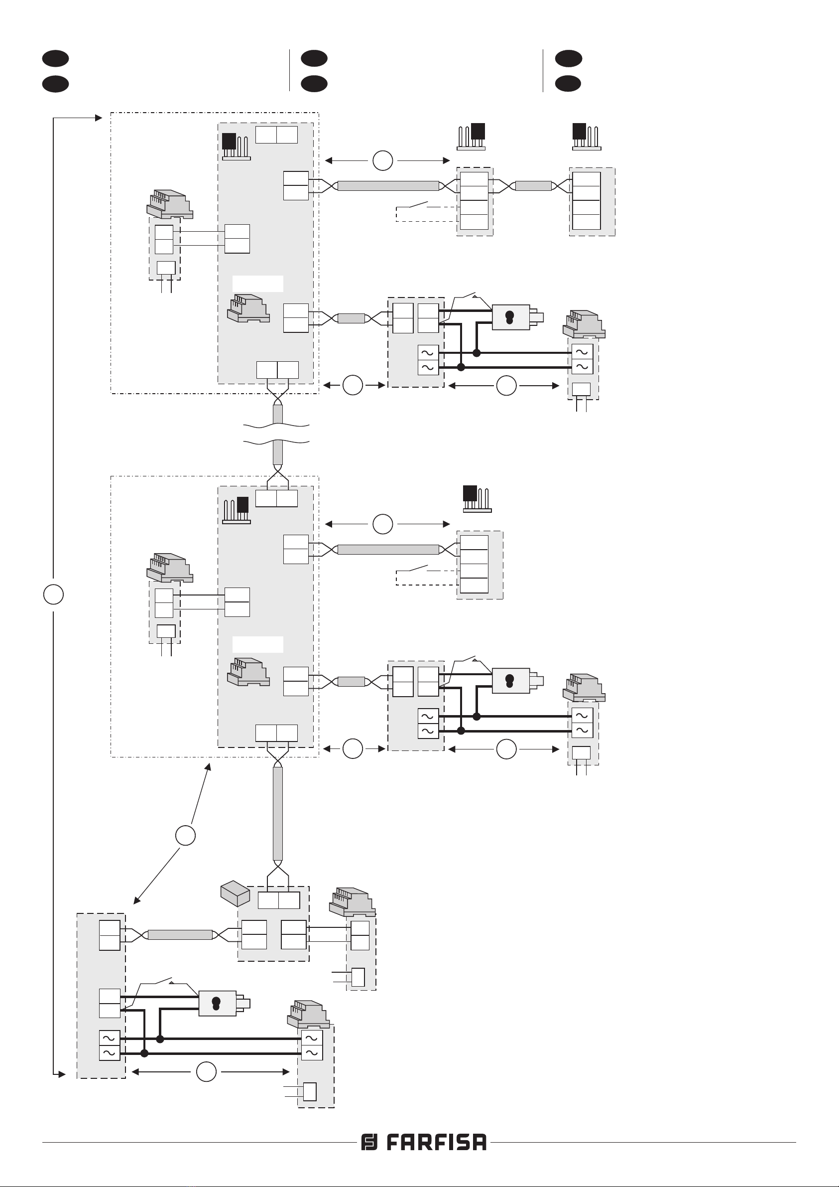
- Para habilitar la placa de calle secundaria,
si se encuentra en la columna montante, hay
que memorizar, en una de las 10 bandas
numéricas, la dirección de la placa de calle
conectada a los terminales LP. Utilice otras
bandas numéricas para la memorización
de las direcciones de eventuales ulteriores
placas de calle conectadas a los terminales
LP.
-Atención: si durante la programación
se comete un error o si en un segundo
momento se quieren modificar las
direcciones memorizadas en el
separador, será necesario borrar toda
lamemoria del dispositivo ejecutando el
procedimiento de borrado de la memoria
y luego volver a programar totalmente el
dispositivo.
Programación de las bandas
numéricas
Para programar las bandas numéricas
F1÷F10, hay que:
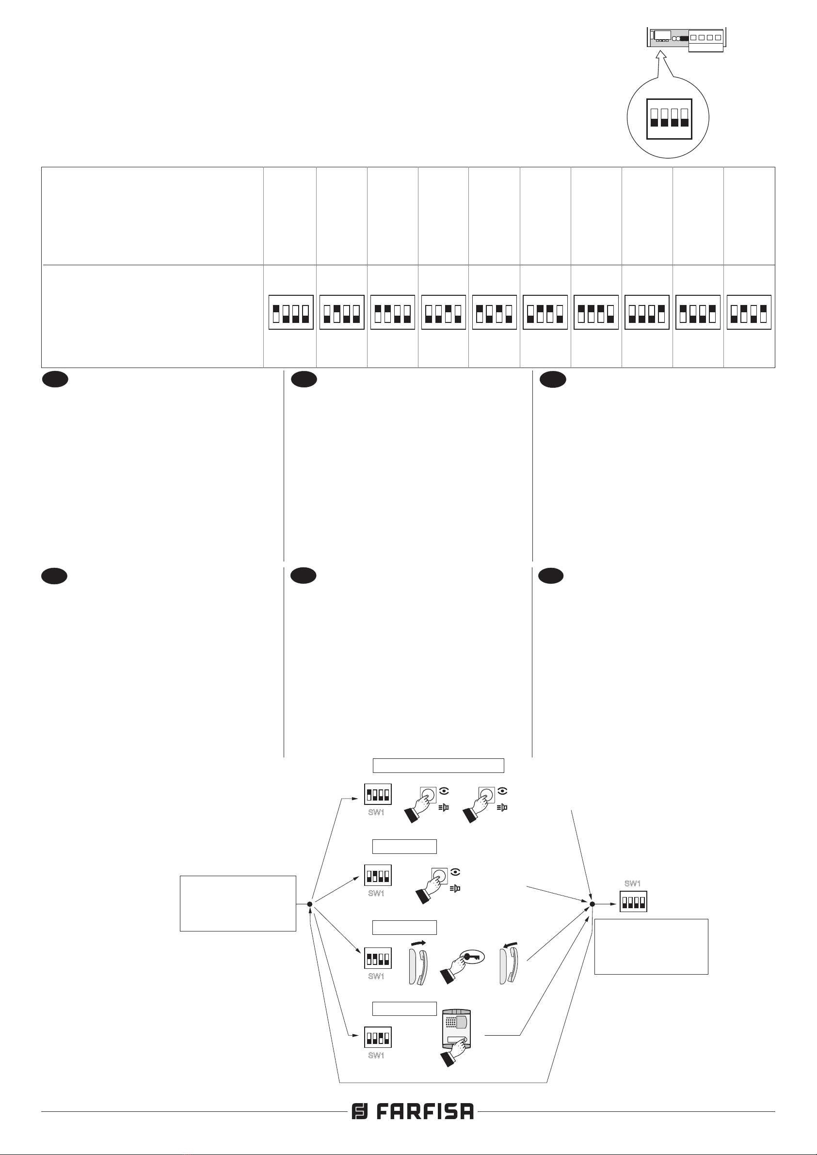
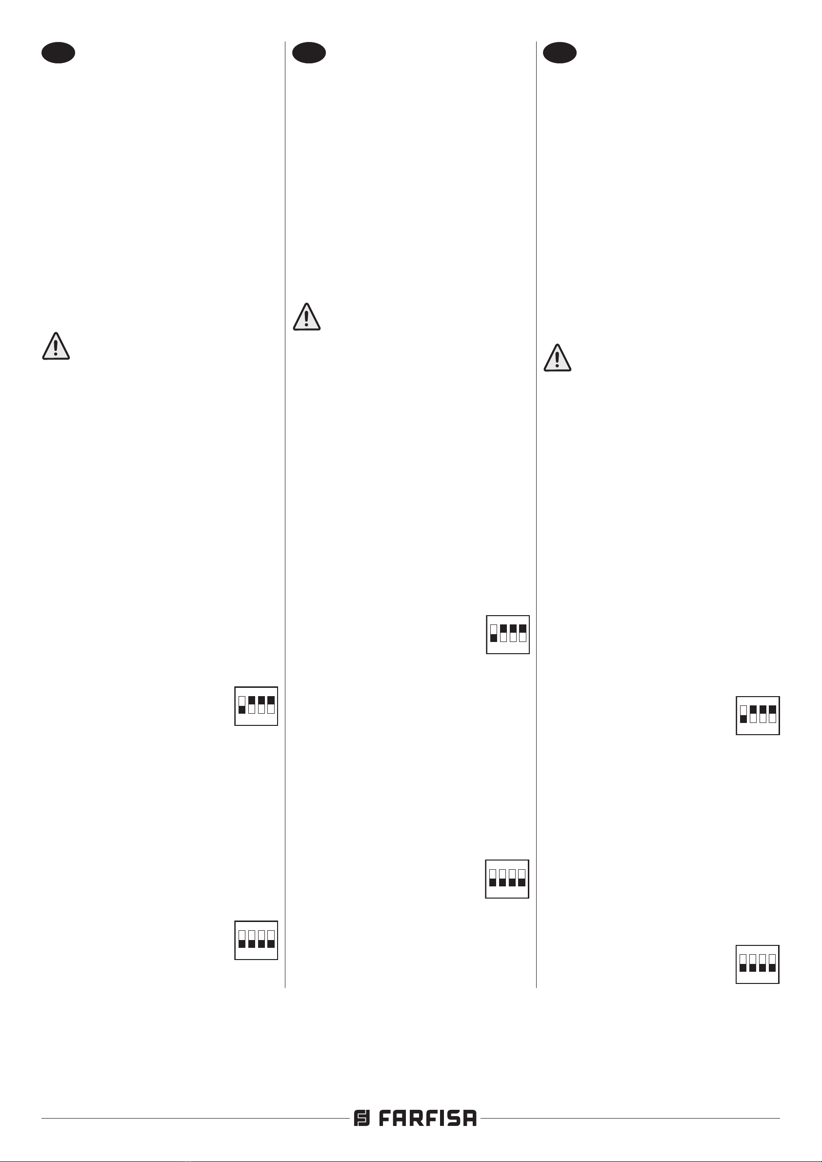
1) seleccione la banda numérica que
hay que programar, posicionando los
microinterruptores de SW1 según las
indicaciones de la tabla 1 de la página
9; el LED rojo parpadea rápidamente.
Por ejemplo, para programar la banda
F1, posicione en ON el
microinterruptor 1 de SW1
dejando en OFF los micro-
interruptores 2, 3 y 4;
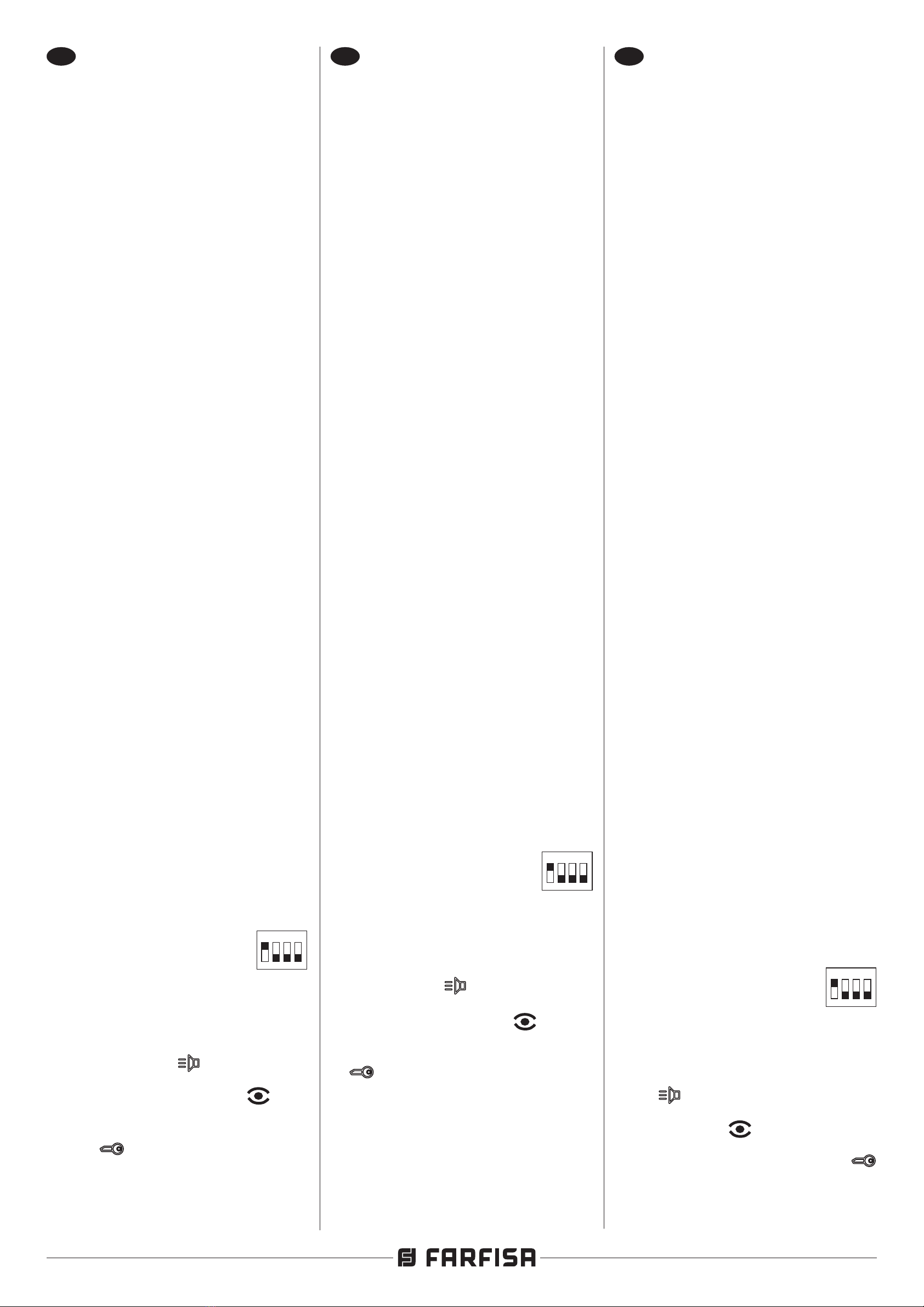
2) memorice la dirección de la placa de calle
o del aparato interno siguiendo el proce-
dimiento que se indica a continuación.
- Por videoportero Zhero ymyLogic,
presionar la tecla
- Por videoportero Echos, Exhito y
Compact, presionar la tecla .
- Por teléfono Exhito y Compact
levantar el microteléfono, presionar la
tecla , colgar el microteléfono.
- Desde lasplacasdecallesecundarias,
realizar una llamada.
En caso de querer programar un grupo
ON
1234
PT
PROGRAMAÇÃO
Informações preliminares
- Para a gestão dos endereços dos video-
porteiros ou telefones conectados à linha
LS estão disponíveis 10 faixas numéricas
(F1÷F10). Em cada faixa numérica pode
ser memorizado o endereço de um único
dispositivo ou então o primeiro e o último
de um grupo de telefones/video-porteiros,
com endereços sequenciais, que se
referem à mesma linha.
Por exemplo, se na faixa F1 memoriza-se
apenas o endereço 100, para a LS será
encaminhada as chamadas endereçadas
apenas ao telefone/video-porteiro 100; se
ao contrário na mesma faixa numérica
F1 for memorizado os números 100 e
120, para a linha LS será encaminhada
as chamadas endereçadas a todos
os telefones/video-porteiros que têm
endereço compreendido entre 100 e 120.
- Para habilitar a botoneira secundária,
quando presente na coluna montante, é
necessário salvar, em uma das 10 faixas
numéricas, o endereço da botoneira liga-
da aos terminais LP. Utilize outras faixas
numéricas para salvar os endereços de
eventuais sucessivas botoneiras coneta-
das aos terminais LP.
-Atenção: se no curso da programação
comete-se um erro ou se em um
segundo momento se quer modicar os
endereços memorizados no separador,
énecessáriocancelartodaamemóriado
dispositivo executando o procedimento
decancelamentoda memória e, então,re-
programar completamente o dispositivo.
Programação das faixas numéricas
Para a programação das faixas numéricas
F1÷F10, é necessário:
1) selecione a faixa numérica a ser
programada posicionando os micro-
interruptores SW1 de acordo com as
indicações da tabela 1 da página 9; o
LED vermelho pisca rapidamente.
Por exemplo, para programar a faixa
F1, posicione em ON o
microinterruptor 1 de SW1,
deixando em OFF os micro-
interruptores 2, 3 e 4;
2) salve o endereço da botoneira ou posto
interno seguindo o procedimento citado
a seguir.
- Por videoporteiro Zhero emyLogic,
premer a tecla
- Por videoporteiro Echos, Exhito e
Compact, premer a tecla .
- Por telefone Exhito e Compact
levantar o micro-telefone, premera tecla
, recolocar o micro-telefone
- Através das botoneiras secundárias
efetue uma chamada.
Caso queira-se programar um grupo
de endereços, primeiramente salve o
endereço com o valor mais baixo.
Se deve-se também programar o
endereço final do grupo na faixa,
prossiga com o ponto 3; do contrário,
ON
1234
DE
PROGRAMMIERUNG
Einleitende Informationen
- Für die Verwaltung der Adressen der
Videosprechgeräte oder Haustelefones,
die mit der Linie LS verbunden sind,
sind für 10 Nummernbereiche (F1÷F10)
verfügbar.
In jedem Nummernbereich kann die
Adresse eines einzelnen Apparates
gespeichert werden oder die erste
und letzte Adresse einer Gruppe von
Videosprechgeräte (Haustelefone) mit
aufeinanderfolgenden Adressen, die
zur gleichen Linie gehören. Wenn zum
Beispiel im Bereich F1 der Linie LS
nur die Adresse 100 gespeichert wird,
dann wird auf LS das nur an die Video-
sprechgerät (Haustelefon) 100 gerichtet
ist weitergeleitet; wenn jedoch im gleichen
Nummernbereich F1 die Zahlen 100
und 120 gespeichert werden, dann
wird auf der Linie LS das Anrufe an alle
Videosprechgeräte (Haustelefone), die
eine Adresse zwischen 100 und 120
haben, weitergeleitet.
- Um die sekundäre Türstation zu aktivie-
ren, falls in der Steigleitung vorhanden,
muss in einem der 10 Nummernbereiche
die Adresse der mit den Anschlussklem-
men LP verbundenen Türstation gespei-
chert werden. Andere Nummernbereiche
für die Speicherung der Adressen von
eventuellen weiteren Türstationen, die mit
den LP-Anschlussklemmen verbunden
sind, verwenden.
-Vorsicht: Wenn man im Laufe der
Programmierung einen Fehler macht oder
wenn man an einem späteren Zeitpunkt
die im Linietrenner gespeicherten
Adressen ändern möchte, dann ist
es notwendig den gesamten Speicher
des Apparates zu löschen und die
Prozedur zur Löschung des Speichers
vorzunehmen und folglich die Vorrichtung
komplett neu zu programmieren.
Programmierung der Nummern-
bereiche
Für die Programmierung der
Nummernbereiche F1÷F10, ist es notwendig:
1) den zu programmierenden Nummern-
bereich auswählen, dabei die
Mikroschalter von SW1 entsprechend
den Angaben von Tabelle 1 auf Seite 9
positionieren
; die rote LED blinkt schnell
auf
.
Um, zum Beispiel, den Bereich F1 zu
programmieren, den Mikroschalter 1
von SW1 auf ON positionieren
und dabei die Mikroschalter 2,
3 und 4 in der OFF-Position
belassen;
2) die Adresse der Türstation oder der
Innenstelle entsprechend dem folglich
wiedergegebenen Vorgang speichern.
- Videosprechgerät Zheround myLogic;
Die Taste drücken
- Videosprechgerät Echos, Exhito und
Compact; Die Taste drücken
- Haustelefon Exhito und Compact;
Das Mikrotelefon anheben, die
Taste drücken, das Mikrotelefon wieder
zurücklegen
- Von den sekundären Türstationen
einen Anruf ausführen.
ON
1234

Mi 2489/3
- 8 -
de direcciones, memorice primero la
dirección con el valor más bajo.
Si en la banda se debe programar
también la dirección nal del grupo,
continúe con el punto 3; si, en cambio,
se debe programar una sola dirección,
pase al punto 4.
Notas.
- La memorización correcta se indica con el
apagado durante un segundo y encendido
sucesivo de manera parpadeante del LED
del separador.
- Eventuales señales acústicas audibles en
esta fase no detectan ninguna anomalía
en la programación.
3) Desde el aparato interno, que tiene
la dirección usuario con el valor más
alto, memorice la dirección siguiendo
el procedimiento elegido. El dispositivo
adquiere la dirección del último aparato
interno que pertenece al grupo,
permitiendo a todos los grupos internos
programados en la banda F1 conectarse
a la línea LS.
4) Volver a colocar en OFFel microinterruptor
1 de SW1. Con esta operación se termina
la fase de programación de la banda F1.
5) Si se desea, continuar de manera
análoga para la programación de las
otras 9 bandas numéricas repitiendo
los puntos de 2 a 5 con la advertencia
de desplazar los microinterruptores
de SW1 de acuerdo con la banda que
se quiere programar (ver tabla 1 de la
página 9).
6) Volver a colocar todos los micro-
interruptores de SW1 en la posición
OFF; el LED rojo vuelve a parpadear
lentamente.
7) Comprobar el correcto funcionamiento
de las placas de calle y de los
videoporteros o teléfonos conectados
a la línea LS del art.2231Q.
Borrado de la memoria
Para borrar los datos introducidos en la
memoria del dispositivo hay que:
- colocar en ON los microinter-ruptores 1,
2 y 4 de SW1 y dejar en OFF
el 3 de SW1; el LED rojo
parpadea rápidamente;
- esperar aproximadamente 4 segundos;
el led rojo quedará encendido de manera
continua;
- dentro de 4 segundos colocar en ON el
microinterruptor 3; el led se
apaga por 2 segundos
aproximadamente, luego
vuelve a parpadear
rápidamente;
- todos los datos memorizados en el
dispositivo se han borrado;
- volver a colocar en OFF todos los
microinterruptores; el led rojo
vuelve a parpadear lentamente.
ON
1234
ON
1234
ON
1234
se deve-se programar somente um
endereço, passe ao ponto 4.
Notas.
- A correta memorização é indicada
pelo desligamento, por um segundo, e
sucessivo acendimento pisca-pisca do
LED do separador.
- Eventuais sinais acústicos audíveisnessa
fase não detectam nenhuma anomalia na
programação.
3) A partir do posto interno que possui o
endereço do utilizador com valor mais
alto, salve o endereço seguindo o
procedimento do modelo escolhido. O
dispositivo adquire o endereço do último
posto interno pertencente ao grupo,
consentindo a todos os postos internos
programados na faixa F1 conetarem-se
à linha LS.
4) Recolocar em OFF o micro-interruptor 1
deSW1. Com essa operação conclui-se
a fase de programação da faixa F1.
5) Se solicitado, prosseguir de modo
análogo para a programação das outras
9faixasnuméricas repetindo os pontos
de 2 a 5 com a advertência de mover os
micro-interruptores de SW1 de acordo
com a faixa que se pretende programar
(ver tabela 1 da página 9).
6) Recolocar todos os micro-interruptores
deSW1naposiçãoOFF;oLEDvermelho
retorna a piscar lentamente.
7) Vericar o correcto funcionamento das
botoneiras e dos video-porteiros ou
telefones conectados à linha LS do
art.2231Q.
Cancelamento da memória
Para cancelar os dados inseridos na
memória do dispositivo, é necessário:
- posicionar em ON os micro-interruptores
1, 2e 4de SW1 e deixe em
OFF o micro-interruptor 3de
SW1; o LED vermelho pisca
rapidamente;
- esperar cerca de 4 segundos; o led
vermelho permanece aceso de modo
contínuo;
- dentro de 4 segundos levar para ON o
micro-interruptor3;o ledapaga-
se por cerca de 2 segundos,
depois, retorna a piscar
rapidamente;
- todos os dados memorizados no
dispositivo foram cancelados;
- recolocar em OFF todos os micro-
interruptores; o led retorna a
piscar lentamente.
ON
1234
ON
1234
ON
1234
Soll eine Adressengruppe gespeichert
werden, so ist die Adresse mit dem
niedrigsten Wert zuerst zu speichern.
Sollte in diesem Bereich auch die
Endadresse der Gruppe gespeichert
werden, dann ist mit Punkt3fortzufahren;
soll jedoch nur eine Adresse gespeichert
werden, dann weiter zu Punkt 4.
Anmerkung.
- Um die ordnungsgemäße Speicherung
anzuzeigen, geht der LED des Trenners
geht eine Sekunde lang aus und fängt
dann wieder an schnell aufzublinken.
- Eventuelle in dieser Phase hörbare
akustische Signale erfassen keine
Anomalie in der Programmierung.
3) Von der Innenstelle, welche die
Benutzeradresse mit dem höchsten Wert
besitzt, die Adresse speichern. Dabei
die Schritte des gewählten Modells
folgen. Das Gerät erfasst die Adresse
der letzten Innenstelle der Gruppe und
ermöglicht den gesamten Innenstellen,
die im Bereich F1 programmiert sind,
sich mit der Linie LS zu verbinden.
4) Den Mikroschalter 1von di SW1wieder auf
OFF zurückstellen. Mit diesem Vorgang
endet die Programmierungsphase des
Bereiches F1.
5) Wenn gefordert, dann die
Programmierung der anderen
9 numerischen Bereiche auf
analoge Weise fortführen und die
Punkte 2 bis 5 mit dem Hinweis
wiederholen, die Mikroschalter von
SW1 in Übereinstimmung mit dem
zu programmierenden Bereich (siehe
Tabelle 1 auf Seite 9) zu verschieben.
6) Alle Mikroschalter von SW1 in die
Position OFF bringen; die rote LED
leuchtet nun wieder langsam auf.
7) Den korrekten Betrieb der Türstationen
und Videosprechgeräte oder Hautelefone
überprüfen, die mit den Linie LS
verbunden sind.
Löschung des Speichers
Um die Daten zu löschen, die in den
Speicher des Apparates eingegeben
wurden, ist es nötig:
- Die Mikroschalter 1, 2 und 4 von SW1 auf
ON stellen dabei den Mikroschalter 3 von
SW1 auf OFF positioniert
lassen; die rote LED beginnt
schnell aufzublinken;
- Zirka 4 Sekunden lang warten; die rote
LED bleibt fortlaufend an;
- Den Mikroschalter 3 innerhalb von 4
Sekunden auf ON stellen; die
LED geht etwa 2 Sek. lang aus,
dann fängt sie wieder an,
schnell zu blinken;
- Alle in der Vorrichtung gespeicherten
Daten wurden gelöscht;
- Alle Mikroschalter wieder auf OFFstellen;
die rote LED blinkt wieder in
langsamen Abständen auf.
ON
1234
ON
1234
ON
1234

- 9 -
Mi 2489/3
ON
1234
ON
1234
ON
1234
ON
1234
ON
1234
ON
1234
ON
1234
ON
1234
ON
1234
ON
1234
4
3
2
1
ON
ON
OFF
1234
LP LP LS LS
LM
LM
LI
LI
LO
LO
1234
MADE IN ITALY
IN: LI-LO Line 0.4W
IN: LM Line max 2.5W
++
+
ON
ON
1
1
2
2
3
3
4
4
SW1
SW1
VC1 (11) VC5 (15)
VC6 (34)
ON
1234
SW1
ENTRATA IN PROGRAMMAZIONE
ENTRADA EM PROGRAMAO
ENTERINGTHE PROGRAMMING MODE
ACCESO ALLA PROGRAMACI N
AUFRUFEN DES PIERMODUS
Ó
ÇÃ
ENTREREN MODEDE PROGRAMMATION
ROGRAMM USCITA DALLA PROGRAMMAZIONE
QUITTERLA PROGRAMMATION
SADADA PROGRAMAO
EXITTHE PROGRAMMING MODE
SALIDADELA PROGRAMACI N
VERLASSEN DES PROGRAMMIERMODUS
Ó
ÍÇÃ
=Echos-Exhito
=Echos-Exhito
=Zhero-myLogic
=Zhero-myLogic
Compact
Compact
F1 (11, 12, 13, 14, 15)
F2 (34)
+
+++
ON
ON
1
1
2
2
3
3
4
4
SW1
SW1
CT (18)
F3 (18)
F4 (231) PEs (231)
Tabella 1 - Posizione dei microinterruttori di SW1 e relativa fascia numerica
Table 1 - Position of SW1’s microswitches and related numerical intervals
Tableau 1 - Position des micro-interrupteurs de SW1 et relative tranche numérique
Tabla 1 - Posición de los microinterruptores de SW1 y relativa banda numérica
Tabela 1 -Posição dos micro-interruptores de SW1 e relativa faixa numérica
Tabelle 1 - Position der Mikroschalter von SW1 und seine Numerischer Bereich
Posizione microinterruttori SW1
Position of SW1’s microswitches
Position micro-interrupteurs SW1
Posición micro-interruptores SW1
Posição dos micro-interruptores SW1
Position der Mikroschalter SW1
Fascia numerica
Numerical interval
Tranche numérique
Banda numérica
Faixa numérica
Numerischer Bereich
F1 F2 F3 F4 F5 F6 F7 F8 F9 F10
IT
Esempio di programmazione
Esempio di programmazione di 4 fasce
(F1÷F4) per il separatore art.2231Q.
Nell'esempio gli interni aventi gli indirizzi
da 11 a 15 (F1), 34 (F2) e 18 (F3) potranno
intercomunicare tra loro o comunicare con
il posto esterno secondario (231) indipen-
dentemente dalla situazione operativa della
linea principale DUO. E' sempre possibile,
da uno degli interni, collegarsi o essere
chiamato dalla linea principale DUO.
EN
Example of programming
Sample programming of 4 intervals (F1÷F4)
for the buer art.2231Q.
In the example, apartments with addresses
from 11 to 15 (F1), 34 (F2) and 18 (F3)
will be able to communicate to each other
or communicate with the secondary door
station (231) regardless of the operational
situation of the DUO main line. From the
apartments is always possible to connect
to or receive a call from the DUO main line.
FR
Exemple de programmation
Exemple de programmation de 4 plages
(F1÷F4) pour un séparateur art.2231Q.
Dans l’exemple les postes internes ayant
les adresses de 11 à 15 (F1), 34 (F2) et
18 (F3) pourront communiquer entre eux
ou communiquer avec la plaque de rue
secondaire (231) indépendamment de la
situation opérationnelle de la ligne principale
DUO. Il est toujours possible, à partir de l’un
des postesinternes, de seraccorder oud’être
appelé depuis la ligne principale DUO.
ES
Ejemplo de programación
PT
Exemplo de programação
DE
Beispiel für Programmierung
Ejemplo de programación de 4 bandas
(F1÷F4) para un separador art.2231Q.
En el ejemplo, los internos que tienen las
direcciones de 11 a 15 (F1), 34 (F2) y 18 (F3)
podrán comunicar entre sí o comunicar con la
placa de calle secundaria (231) independien-
temente de la situación operativa de la línea
principal DUO. Siempre es posible, desde
uno de los internos, conectarse o ser llamado
por la línea principal DUO.
Exemplo de programação de 4 faixas
(F1÷F4) para um separador art.2231Q.
No exemplo, os módulos internos que
possuem os endereços de 11 a 15 (F1),
34 (F2) e 18 (F3) poderão intercomunicar
entre si ou comunicar com a botoneira
secundária (231) independentemente da
situação operativa da linha principalDUO. É
sempre possível, apartir de umdos módulos
internos, ligar ou ser chamado pela linha
principal DUO.
Programmierbeispiel von 4 Bereichen
(F1÷F4) für einen Trenner Art.2231Q.
Im Beispiel können die Innenstellen mit den
Adressen von 11 bis 15 (F1), 34 (F2) und 18
(F3) untereinander kommunizieren oder mit
der sekundäre Türstation (231) in Verbindung
treten, unabhängig vom Betriebszustand
der Hauptlinie DUO. Es ist stets möglich,
von einer der Innenstellen mit der Hauptlinie
DUO in Verbindung zu treten oder von dieser
angerufen zu werden.

Mi 2489/3
- 10 -
IT
DUO a Range Esteso
Caratteristiche Funzionali
Il separatore di montanti art. 2231Q è
compatibile con i sistemi digitali DUO e ne
aumenta le potenzialità prevedendo la pos-
sibilità di dividere l’impianto in 99 blocchi
con 253 dispositivi ciascuno: nel sistema
possono quindi essere installati più di 25000
dispositivi (Sistema Duo a Range Esteso).
Per ottenere tali prestazioni è necessario
che ogni separatore sia individuato da un
indirizzo di blocco (sezione dell’impianto a
cui il dispositivo appartiene: da 01 a 99); il
blocco 00 (ovvero blocco non programmato)
è riservato per la compatibilità con i prodotti
e le schematiche DUO esistenti. All'interno
di ciascun blocco possono essere collegati
altri 253 dispositivi.
Attenzione: per il corretto funziona-
mento del sistema i posti esterni principali e
i dispositivi collegati alle linee LI-LI oppure
LO-LO, devono essere predisposti per il
funzionamento DUO a Range Esteso,
mentre i posti esterni secondari e i dispo-
sitivi collegati alle linee LP-LP oppure LS-
LS, possono essere del tipo tradizionale
(DUO). I posti esterni secondari, collegati
alla linea LS-LS,devono avere obbligato-
riamente un indirizzo compreso tra 245 e
253, indirizzi che ovviamente non possono
essere attribuiti ai posti esterni principali per
i quali rimangono a disposizione gli indirizzi
compresi tra 231 e 244.
Programmazione del separatore
Per il funzionamento in modalità Duo a
Range Esteso è necessario programmare
l'indirizzodi blocco delseparatoreart. 2231Q
come riportato di seguito:
1) posizionare in ON i microinterruttori
2,3 e4 di SW1 lasciando in OFF il
microinterruttore 1;
4
3
2
1
ON
il LED rosso lampeggia
velocemente.
2) Da uno dei posti esterni secondari,
collegati agli ingressi LP-LP del
dispositivo, eettuare una chiamata
al numero di blocco desiderato, il
dispositivo acquisisce automaticamente
il valore. Per esempio se nel separatore
art. 2231Q si intende programmare
l'indirizzo di blocco 24, è necessario
inviare, dal posto esterno secondario ad
esso collegato, una chiamata al numero
24.
3) Riportare in OFF tutti i microinterrut-
tori di SW1;
4
3
2
1
ON
il LED rosso ritorna a lampeg-
giare lentamente
EN
DUO Extended Range
Functional Features
The Line Buer 2231Q is compatible with
DUO digital systems and increases their
potentialities by allowing the system to be
divided into 99 blocks with 253 devices
each. Over 25,000 devices can therefore
be installed in the system (Duo System
Extended Range). To achieve this, each
buer is identied by a block address
(block of the system to which the device
belongs: from 01 to 99). The block 00 (i.e.
not programmed) is reserved for compat-
ibility with the existing products of DUO
systems. Within each block 253 other de-
vices can be connected.
Warning: for correct operation of
the system the main entrance units and
devices connected to LI-LI or LO-LO lines
must be set up for the DUO Extended
Range, while the secondary entrance
units and devices connected to LP-LP or
LS-LS lines may be of the traditional type
(DUO). Secondary entrance door stations
connected to the LS-LS line must have ad-
dresses between 245 and 253, address-
es which cannot be attributed to the main
entrance door stations, which can have
addresses between 231 and 244.
Line buer programming
For operation in Duo Extended Range
mode, the block address of the 2231Q Line
Buer must be programmed as follows:
1) position microswitches 2,3 and 4 of
SW1 to ON, leaving switch 1 OFF.
The red LED should ash
4
3
2
1
ON
quickly.
2) From one of the secondary entrance
door stations, connected to the LP-
LP inputs of the device, make a call
to the desired block number and the
device will automatically store the val-
ue. For example, if you want to pro-
gramme the address of block 24 in
the 2231Q Line Buer, you must send
a call, from the secondary entrance
door station, connected to it, to the
number 24.
3) Return all the microswitches of SW1
to OFF.
4
3
2
1
ON
The red LED should return to
blinking slowly.
Caractéristiques Fonctionnelles
Le séparateur de montants art. 2231Q
est compatible avec les systèmes DUO et
augmente ses potentialités en prévoyant
la possibilité de diviser l’installation en 99
blocs avec 253 dispositifs chacun: dans
les systèmes peuvent donc être installés
plus de 25000 dispositifs (Système Duo
à Large Range). Pour obtenir ces presta-
tions il est nécessaire pour chaque sépa-
rateur qu’il soit identié par une adresse
de bloc (section de l’installation à laquelle
le dispositif appartient : de 01 à 99); le bloc
00 (c’est-à-dire bloc non programmé) est
réservé pour la compatibilité avec les pro-
duits et les schématiques DUO existantes.
A l’intérieur de chaque bloc peuvent être
raccordé 253 autres dispositifs.
Attention: Pour le fonctionnement
correct du système les postes externes
principaux raccordés aux lignes LI-LI ou
LO-LO, doivent être prédisposés pour le
fonctionnement DUO à Large Range, tan-
dis que les postes externes secondaires et
les dispositifs reliés aux lignes LP-LP ou
LS-LS, peuvent être du type traditionnel
(DUO). Les postes externes secondaires,
raccordés à la ligne LS-LS, doivent avoir
une adresse comprise entre 245 et 253,
adresses qui ne peuvent être attribuées
aux postes externes principaux pour les-
quels restent à disposition les adresses
comprises entre 231 et 244.
Programmation du séparateur
Pour le fonctionnement en modalité Duo
à Large Range il est nécessaire de pro-
grammer de bloc du séparateur art. 2231Q
comme reporté ci-après:
1) placer sur ON les micro-interrup-
teurs 2,3 et 4de SW1 en laissant sur
OFF le microinterrupteur 1;
4
3
2
1
ON
la LED rouge clignote rapide-
ment.
2) D’un des postes externes secon-
daires, raccordés aux entrées LP-
LP du dispositif, eectuer un appel au
numéro de bloc souhaité, le dispositif
acquiert automatiquement la valeur.
Par exemple si dans le séparateur
art. 2231Q on entend programmer
l’adresse de bloc 24, il est nécessaire
d’envoyer, du poste externe secon-
daire raccordé à celui-ci, un appel au
numéro 24.
3) Reporter sur OFF tous les micro-in-
terrupteurs de SW1;
4
3
2
1
ON
la LED rouge clignote à nou-
veau lentement.
FR
DUO à Large Range

- 11 -
Mi 2489/3
ES
DUO de Gama Extendida
Características funcionales
El separador de montantes 2231Q es
compatible con los sistemas digitales DUO
y aumenta las potencialidades previendo
la posibilidad de dividir la instalación en 99
bloques con 253 dispositivos cada uno:
en el sistema se pueden instalar pues más
de 25000 dispositivos (Sistema Duo de
Gama Extendida). Para obtener estas
prestaciones es necesario que cada se-
parador sea individuado por una dirección
de bloque (sección de la instalación a la
que pertenece el dispositivo: de 01 a 99);
el bloque 00 (o sea el bloque no programa-
do) está reservado para la compatibilidad
con los productos y los esquemas DUO
existentes. En el interior de cada bloque
pueden conectarse otros 253 dispositivos.
Atención: para el correcto funcio-
namiento del sistema las placas de calle
principales y los dispositivos conectados a
la líneas LI-LI o LO-LO, deben estar pre-
dispuestos para el funcionamiento DUO de
Gama Extendida, mientras que las placas
de calle secundarias y los dispositivos co-
nectados a las líneas LP-LP o LS-LS pue-
den ser tipo tradicional (DUO). Las pla-
cas de calle secundarias, conectados a la
línea LS-LS, deben tener obligatoriamente
una dirección entre 245 y 253, direccio-
nes que obviamente no pueden atribuirse
a las placas de calle principales para los
cuales permanecen a disposición las di-
recciones entre 231 y 244.
Programación del separador
Para el funcionamiento en modalidad Duo
de Gama Extendida es necesario progra-
mar la dirección de bloqueo del separador
2231Q como se indica a continuación:
1) ponga en ON los micro-interrupto-
res 2, 3 y 4 de SW1 dejando en OFF
el micro-interruptor 1;
4
3
2
1
ON
el LED rojo está intermitente
rápido.
2) Desde uno de las placas de calle
secundarias, conectados a los in-
gresos LP-LP del dispositivo, efec-
túe una llamada al número de bloque
deseado, el dispositivo adquiere au-
tomáticamente el valor. Por ejemplo
si en el separador 2231Q se desea
programar la dirección de bloque 24,
es necesario efectuar una llamada al
número 24 desde la placa de calle co-
nectado a este.
3) Regrese a OFF todos los micro-in-
terruptores de SW1;
4
3
2
1
ON
el LED rojo vuelve a ponerse
intermitente y lento.
ES
DUO de Gama Extendida
Características Funcionais
O separador de montantes 2231Q é com-
patível com os sistemas digitais DUO e
aumenta as potencialidades ao prever a
possibilidade de dividir a instalação em 99
blocos com 253 dispositivos cada um:
no sistema podem ser instalados mais
de 25.000 dispositivos (Sistema DUO de
Amplitude Estendida). Para obter tais
prestações, é necessário que cada sepa-
rador seja identicado por um endereço de
bloco (seção da instalação a qual o dispo-
sitivo pertence: de 01 a 99); o bloco 00 (ou
seja, bloco não programado) é reservado
pela compatibilidade com os produtos e os
esquemas DUO existentes. No interior de
cada bloco podem ser ligados outros 253
dispositivos.
Atenção: para o funcionamento
correto do sistema em botoneiras princi-
pais, os dispositivos ligados às linhas LI-LI
ou LO-LO devem ser predispostos para o
funcionamento DUO de Amplitude Esten-
dida, enquanto as botoneiras secundárias
e os dispositivos ligados às linhas LP-LP
ou LS-LS podem ser do tipo tradicional
(DUO). As botoneiras secundárias, ligados
à linha LS-LS, devem ter obrigatoriamente
um endereço compreendido entre 245
e 253, endereços que, obviamente, não
podem ser atribuídos as botoneiras prin-
cipais para as quais permanecem à dispo-
sição os endereços compreendidos entre
231 e 244.
Programação do separador
Para o funcionamento na modalidade
DUO de Amplitude Estendida é neces-
sário programar o endereço do bloco do
separador 2231Q, como descrito a seguir:
1) posicionar em ON os micro-interrup-
tores 2, 3 e 4de SW1, deixando em
OFF o micro-interruptor 1;
4
3
2
1
ON
o LED vermelho pisca rapida-
mente.
2) De uma das botoneiras secundá-
rias, ligados às entradas LP-LP do
dispositivo, efectuar uma chamada ao
número do bloco desejado, o disposi-
tivo adquire automaticamente o valor.
Por exemplo, se no separador 2231Q
se pretende programar o endereço do
bloco 24, é necessário enviar, da bo-
toneira secundária a ele ligado, uma
chamada ao número 24.
3) Recolocar em OFF todos os micro-
interruptores de SW1;
4
3
2
1
ON
o LED vermelho volta a pis-
car lentamente.
Funktionsmerkmale
Der Trennverstärker Artikel Nr. 2231Q ist
mit den digitalen DUO-Systemen kompa-
tibel und verbessert die Leistungsfähigkeit
durch die Möglichkeit der Aufteilung der
Anlage in 99 Blöcke mit jeweils 253 Ge-
räten: in die Anlage können daher mehr als
25000 Geräte installiert werden (Duo-Sys-
tem mit erweiterter Reichweite). Um die-
se Vorteile nutzen zu können, muss jede
Trennvorrichtung durch eine Bockadresse
gekennzeichnet werden (Abschnitt der An-
lage, zu welchem das Gerät gehört: von
01 bis 99); der Block 00 (d.h. nicht pro-
grammierter Block) ist die Kompatibilität
mit den bestehenden Produkten und den
DUO-Diagrammen. In jedem Block kön-
nen weitere 253 Geräte angeschlossen
werden.
Vorsicht: für den korrekten Be-
trieb des Systems müssen die Haupt-Au-
ßenstationen und Geräte, die an die Lei-
tungen LI-LI oder LO-LO angeschlossen
sind für den Betrieb DUO mit erweiterter
Reichweite vorbereitet sein, während die
sekundären Außenstationen und Geräte,
die an die Leitungen LP-LP oder LS-LS
angeschlossen sind, vom traditionellen
Typ (DUO) sein können. Die sekundären
Außenstationen, die an die Leitung LS-LS
angeschlossen sind, müssen unbedingt
eine Adresse zwischen 245 und 253 ha-
ben, Adressen die oensichtlich nicht an
die Haupt-Außenstationen vergeben wer-
den können, für diese sind die Adressen
zwischen 231 und 244 vorgesehen.
Programmierung der Trennvorrichtung
Für den Betrieb in der Betriebsweise Duo
mit erweiterter Reichweite muss die
Blockadresse der Trennvorrichtung Artikel
Nr. 2231Q folgendermaßen programmiert
werden:
1) die Mikroschalter 2, 3 und 4 der SW1
auf ON stellen und den Mikro-
4
3
2
1
ON
schalter 1 auf OFF lassen;
die rote LED blinkt schnell.
2) Von einer der sekundären Außensta-
tionen, verbunden an die LP-LP Ein-
gänge des Gerätes, einen Anruf an
die gewünschte Blocknummer durch-
führen, das Gerät erfasst automatisch
den Wert. Zum Beispiel, wenn in der
Trennvorrichtung Artikel Nr. 2231Q
versucht wird, die Blockadresse 24
zu programmieren, muss von der se-
kundären Außenstation an welche sie
angeschlossen ist, ein Anruf an die
Nummer 24 gesendet werden.
3) Alle Mikroschalter der SW1 wieder
auf OFF stellen;
4
3
2
1
ON
die rote LED blinkt wieder
langsam.
DE
DUO-System mit erweiter-
ter Reichweite

Mi 2489/3
- 12 -
ACI srl Farsa Intercoms
Via E. Vanoni, 3 • 60027 Osimo (AN) • Italy
Tel: +39 071 7202038 (r.a.) • Fax: +39 071 7202037
e-mail: info@acifarsa.it • www.acifarsa.it
Directive 2012/19/EU (WEEE-RAEE)
Smaltire il dispositivo secondo quanto prescritto dalle norme per la tutela dell'ambiente.
Dispose of the device in accordance with environmental regulations.
Écouler le dispositif selon tout ce qu'a été prescrit par les règles pour la tutelle du milieu.
Eliminar el aparato según cuánto prescrito por las normas por la tutela del entorno.
Disponha do dispositivo conforme regulamentos ambientais.
Werden Sie das Gerät in Übereinstimmung mit Umweltregulierungen los.
La ACI Srl Farsa Intercoms si riserva il diritto di modicare in qualsiasi momento i prodotti qui illustrati.
ACI Srl Farsa Intercoms reserves the right to modify the products illustrated at any time.
La ACI Srl Farsa Intercoms se réserve le droit de modier à tous moments les produits illustrés.
Mi2489/3
Cod. M527052720
ACI Srl Farsa intercoms se reserva el derecho de modicar en cualquier momento los productos ilustrados aquí.
E’ reservada a ACI Srl Farsa intercoms o direito de modicar a qualquer momento os produtos aqui ilustrados.
Änderungen vorbehalten.
LM
LM
PA
SE
PEp (231)
TD2000
LP
LP
LILI
LOLO
J1=3-4
1234
2231Q
PEs (245)
LP
LP
LS
LS
LP
LP
Agorà Light
Solvo
Alba
DV2420
LI
LI
LOLO
LM
LM
22 12MQ
2221S
LP
LP
127/230Vac
S+
S-
PB
GN
Linea DUO
DUO Line
Ligne DUO
Linea DUO
Linha DUO
Linie DUO
LM
LM
LILI
LOLO
J1=3-4
1234
2231Q
LP
LP
LS
LS
LM
LM
22 12MQ
2221S
LP
LP
127/230Vac
LILI
LOLO
J1=1-2 (100 )
1234
2231Q
PEs (245)
LP
LP
LS
LS
LP
LP
Agorà Light
Solvo
Alba
Sistema DUO Tradizionale
Conventional DUO System
Système DUO Traditionnel
Sistema DUO Tradicional
Traditionelles DUO-System
Sistema DUO a Range Esteso
Extender Range DUO System
Système DUO à Large Range
Sistema DUO de Gama Extendida
Sistema DUO de Amplitude Estendida
DUO-System mit erweiterter Reichweite
Linea DUO
DUO Line
Ligne DUO
Linea DUO
Linha DUO
Linie DUO
Linea DUO
DUO Line
Ligne DUO
Linea DUO
Linha DUO
Linie DUO
BLOCCO N° ..n - BLOCK No ..n
BLOC N° ..n - BLOQUE N° ..n
BLOCO N° ..n - BLOCK Nr ..n
Agorà Light
Solvo
Alba
22 12MQ
2221S
LP
LP
127/230Vac
PEs (245)
LP
LP
Agorà Light
Solvo
Alba
22 12MQ
2221S
LP
LP
127/230Vac
BLOCCO N° 2 - BLOCK No 2
BLOC N° 2-BLOQUE N° 2
BLOCO N° 2 - BLOCK Nr 2
BLOCCO N° 1 - BLOCK No 1
BLOC N° 1-BLOQUE N° 1
BLOCO N° 1 - BLOCK Nr 1
PDX2000
LOLO
LILI
A
J
T
G
PW
D
M
B
K
U
H
QX
E
N
C
L
V
I
RY
SZ
F
O
1
4
7
2
5
8
0
3
6
9
IT
Esempio installativo
EN
Example of installation
FR
Exemple de installation
ES
Ejemplo de conexión
PT
Exemplo de ligação
DE
Anschlussbeispiel
Table of contents
Popular Water Filtration System manuals by other brands

Eden
Eden 511 instructions

Gardner Denver
Gardner Denver FIL Series manual

Donaldson
Donaldson PowerCore CPC Series Installation, operation and maintenance manual

Cillit
Cillit Claropur BW Installation and operating manual

Sanitron
Sanitron S2400C Installation operation & maintenance

AFS
AFS MD500 Series Operation & maintenance manual

Sera
Sera UV-C-System Assembly instruction

BWT
BWT Celsius 80 Installation and operating manual

GE
GE GXSL55R Owner's manual and installation instructions

Hydac
Hydac FAM 5 FluidAqua Mobil Operating and maintenance instructions

brondell
brondell H625 Pearl owner's manual

Kessel
Kessel 99601.002B Installation and operating instructions