manuals.online logo
Brands
  1. Home
  2. •
  3. Brands
  4. •
  5. Mahr
  6. •
  7. Measuring Instrument
  8. •
  9. Mahr 40 AG User manual

Mahr 40 AG User manual

Printed in Germany
0605
Bedienungsanleitung
Operating Instructions
Instructions de Service
Bügelmessschraube
Micrometer
Micrométre
40 AG/W
Mahr GmbH Esslingen
D-73702 Esslingen • Postfach 10 02 54
Telefon (07 11) 9 31 26 00 • Fax (07 11) 3 16 09 53
3758429
Beschreibung
1 Schnelltrieb
2 Messtrommel mit integrierter Ratsche
3 Hülse
4 Messspindel
5 Einstellmutter
6 Feststelleinrichtung
7 Bügel
8 Messflächen
9 Amboss
10 Hakenschlüssel
F
D
USA
GB
F
D
USA
GB
Justieren der Nullstellung
Einstellen auf Null
– Messflächen reinigen
– Messspindel 4mit Messtrommel 2unter Einsatz der
Ratsche an Amboss 9oder Einstellmaß anlegen
– Abweichung des Null-Striches der Messtrommel 2
gegenüber der Null-Linie der Hülse 3feststellen
– Messspindel 4einige Umdrehungen zurückschrauben
– Mit Hakenschlüssel 10 die Hülse 3um die festgestellte
Abweichung drehen.
– Zur Prüfung Messspindel 4mit Schnelltrieb 1an
Amboss 9oder Einstellmaß anlegen und Übereinstim-
mung von Null-Linie der Messhülse mit Null-Strich der
Messtrommel prüfen. Bei noch vorhandener Differenz
Nachstellung verbessern.
Hinweis:
Nach mehrmaligem Nachstellen kann die Null-Linie der
Messhülse in eine ungünstige Messstellung kommen.
– Messhülse in die günstigste Stellung zurück drehen und
die genaue Einstellung an der Messtrommel vornehmen.
– Schnelltrieb lösen; Messtrommel durch mäßiges Klopfen
mit einem Holz lockern und in die richtige Stellung bringen.
Nachstellen bei Spindelspiel
– Spindel mit Messtrommel herausschrauben. Lage der
Feststelleinrichtung 6nicht verändern.
– Die Einstellmutter 5geringfügig lösen, bis der erforder-
liche spielfreie Gang der Messspindel 4 erreicht ist.
– Messspindel wieder in den Schaft einführen und
vorsichtig einschrauben. Achtung! Gewindegänge
dabei nicht beschädigen.
– Nullstellung kontrollieren und gegebenenfalls auf Null
einstellen.
Adjusting the zero position
Setting to zero
– Clean measuring faces
– Turn thimble 2 using the ratchet until the measuring
spindle 4makes contact with the anvil 9or a setting
standard
– Determine the deviation between the zero line on the
thimble 2and the reference line on the barrel 3
– Unscrew the measuring spindle 4 a few turns
– Apply the hook spanner 10 to the barrel 3and turn to
the previously determined deviation
– Examine whether the reference line on the barrel is
aligned the with the zero line on measuring spindle 4,
turn the measuring spindle using the rapid drive until
contact is made with the anvil 9 or the setting standard,
if necessary this process must be repeated.
Note:
After repeated adjustments the reference line on the barrel
maybe in a inconvenient reading position.
– Reset the barrel to a convenient reading position and
then make the adjustments to the thimble
– Loosen the rapid drive; loosen the thimble by tapping it
with a piece of wood and set in the correct position.
Readjust in case of spindle play
– Unscrew the measuring spindle and thimble, do not
alter the position of the clamping device 6
– Slightly undo the setting nut 5until the point is reached
were the spindle 4is completely free of play
– Return the spindle to its shank and carefully screw it
back into position. Attention! Be extremely cautious
so as not to damage the first threads
– Check the zero position, and if necessary set to zero.
Remise à zéro
Ajustage de la position zéro (fig. c)
– Nettoyer les faces mesurantes
– Utiliser l’avance rapide 1avec tambour 2pour mettre
en contact la vis micrométrique 4avec la touche 9 ou
alors utiliser un étalon de réglage.
– Déterminer la déviation de la ligne « 0 » sur le tambour
2par rapport à la ligne « 0 » du vernier.
– Resserrer la vis micrométrique 4de quelques tours.
– A l’aide de la clef 10 tourner le vernier 3par la
déviation déterminée précédemment.
– Pour contrôler si le « 0 » du vernier est aligné au « 0 »
du tambour 2, tourner la vis micrométrique 4en
utilisant l’avance rapide 1pour en mettre en contact
avec la touche 9ou alors utiliser un étalon de réglage.
En cas de déviation encore existante, il faut répéter le
procédé.
Remarque :
Après des rajustages répétés la ligne de référence sur le
vernier peut être dans une position de lecture inconvéniente.
–Ramener le vernier sur la position la plus convéniente et
procéder à l’ajustage exact sur le tambour
–Desserrer le système d’avance rapide ; frapper très
légèrement avec une pièce de bois sur la roue de fiction
et la mettre dans la position correcte
Rajustage en cas de jeu de la vis micrométrque
–Dévisser la vis micrométrique avec le tambour. Ne pas
changer la position du dispositif de blocage 6.
–Desserrer très légèrement le cône 5jusqu’au point où la
vis micrométrique 4est complètement sans jeu
–Remettre la vis micrométrique dans la queue et la visser
avec précaution dans la position correspondante.
Attention ! Ne pas en endommager les pas des vis.
–Contrôler la position zéro et si nécessaire rajuster au
point zéro.
69 835421
7
10
8
Description
1 Avance rapide
2 Tambour avec bouton à friction
intégré
3 Vernier
4 Vis micrométrique
5 Cône
6 Dispositif de blocage
7 Etrier
8 Faces mesurantes
9 Touche de mesure
10 Clef pour l’étalonnage
Description
1 Rapid drive
2 Thimble with integrated ratchet
3 Barrel
4 Measuring spindle
5 Setting nut
6 Clamping device
7 Frame
8 Measuring faces
9 Anvil
10 Hook spanner
Wichtige Hinweise vor Gebrauch
• Verschmutzungen der Messflächen beeinflussen das
Messergebnis. Die Messflächen sollten daher stets frei
von Staub und Schmutz sein.
• Sollte in der Grundstellung die Skalenlinie „0“ der
Trommel nicht mit der Bezugslinie übereinstimmen,
muss die Nullstellung justiert werden.
Wir wünschen Ihnen viel Erfolg beim Einsatz Ihrer Bügel-
messschraube. Falls Sie Fragen haben, stehen Ihnen
unsere technischen Berater gerne zur Verfügung.
Einleitung
Die Bügelmessschraube 40 AG/W ist ein vielseitig
einsetzbares Präzisionsinstrument für den wirtschaftlichen
Einsatz in der Fertigung und im Messraum. Vor Inbetrieb-
nahme des Geräts empfehlen wir Ihnen, die Bedienungs-
anleitung aufmerksam zu lesen.
Zur Grundausstattung der Bügelmessschraube 40 AG/W
gehört:
– Bügelmessschraube 40 AG/W
– Einstellmaß
– Hakenschlüssel
– Bedienungsanleitung
F
D
USA
GB
Pflege der Messschraube
– Bügelmessschraube von Staub und Schmutz reinigen
– Zum Reinigen des Spindelgewindes die Spindel
herausschrauben
– Gewinde mit Waschbenzin reinigen und synthetisches
Öl auftragen
– Auf Spindel und Amboss ein synthetisches Öl auf-
tragen.
F
D
USA
GB
Service of the Micrometer
– Remove dust and dirt from the Micrometer
– To clean the spindle threads unscrew the spindle
– Clean the thread with petroleum ether followed by the
application of a trace of synthetic oil
– Apply a trace of synthetic oil to spindle and anvil.
Entretien du micromètre
– Eliminer toute trace de poussière ou de copeaux
– Dévisser totalement la vis micrométrique
– Le nettoyage des différentes parties devra se faire
avec du pétrole
– Appliquer une mince couche d’huille après nettoyage.
Nota: il ne faudra utiliser que de l’huile synthétique.
Important hints prior to use
• Contamination of the measuring faces affects the
measuring result therefore they should always be kept
free of dust and dirt particles.
• Should the „0“- line of the thimble scale in the basic
setting not align with the reference line then it is
necessary to carry out a zero adjustment.
We wish you a satisfactory and long service of your
Micrometer. Should you have any questions regarding the
instrument, please contact us and our technical advisors
will be pleased to answer them.
Introduction
The Micrometer 40 AG/W is versatile precision measuring
instrument for use in a production environment and in the
inspection department. In order to achieve the best use of
this measuring instrument it is most important that you read
these operating instructions first.
Basically the Micrometer 40 AG/W consists of:
– Micrometer 40 AG/W
– Setting standard
– Hook spanner
– Operating instructions
Indications importantes avant l’utilisation
• La détérioration des faces mesurantes affecte le
résultat de la mesure. Elles devront par conséquent
toujours êtres protégées de la poussière ou des
copeaux.
• En position normale, le „0“ du barillet doit être aligné
avec le „0“ du vernier. Le cas échéant, il sera alors
nécessaire de procéder à un étalonnage (ajustement
du „0“).
Nous vous souhaitons une excellente utilisation de votre
Micromètre 40 A. Pour tous renseignements complémen-
taires, contactez-nous, nos conseillers techniques se feront
un plaisir de vous renseigner.
Introduction
Le Micromètre 40 AG/W est un instrument de mesure de
prècision polyvalent. C’est une solution économique pour
les cas de mesure en atelier ou en salle de contrôle. Afin
d’utiliser au mieux cet instrument de mesure, nous vous
engageons vivement à lire, avant toute utilisation, les
instructions suivantes.
La livraison du Micromètre 40 AG/W comprend:
– un Micromètre 40 AG/W
– Mesure de réglage
– une clef pour l’étalonnage
– les instructions de service.
Ablesen der Messschraube
Messschrauben mit Teilung 0,01 mm
Hülse 2,5
Trommel 0,28
Messergebnis 2,78 mm
Achtung!
Es ist darauf zu achten, dass senkrecht zur Referenzlinie
abgelesen wird, um Parallaxfehler zu vermeiden.
25
30
0
F
D
USA
GB
Reading the Micrometer
Micrometer with 0,01 mm-divisions
Barrel 2,5
Thimble 0,28
Measuring result 2,78 mm
Note!
Please ensure that you read the result perpendicular to the
reference line to avoid parallax errors.
Lecture du micromètre
micromètre au 0,01 mm
Vernier 2,5
Tambour 0,28
Résultat de mesure 2,78 mm
Note:
Pour éviter toute mauvaise interprétation de la lecture,
assurez-vous de bien lire le résultat en étant
perpendiculaire à la ligne de référence du vernier.
25
30
0
25
30
0

This manual suits for next models

1

Other Mahr Measuring Instrument manuals

Mahr Digimar 817 CLT User manual

Mahr

Mahr Digimar 817 CLT User manual

Mahr Millimar S 1840 User manual

Mahr

Mahr Millimar S 1840 User manual

Mahr MarSurf PS 10 Quick guide

Mahr

Mahr MarSurf PS 10 Quick guide

Mahr Digimar M 814 G User manual

Mahr

Mahr Digimar M 814 G User manual

Mahr Micromar 44 EWR User manual

Mahr

Mahr Micromar 44 EWR User manual

Mahr Pocket Surf IV User manual

Mahr

Mahr Pocket Surf IV User manual

Mahr Millimar C 1202 User manual

Mahr

Mahr Millimar C 1202 User manual

Mahr MarCal 30 EWN User manual

Mahr

Mahr MarCal 30 EWN User manual

Mahr Multimar 844 T User manual

Mahr

Mahr Multimar 844 T User manual

Mahr umaxum II User manual

Mahr

Mahr umaxum II User manual

Mahr MarSurf PS 10 User manual

Mahr

Mahr MarSurf PS 10 User manual

Mahr MarTest 802 NW User manual

Mahr

Mahr MarTest 802 NW User manual

Mahr Millimar C 1202 User manual

Mahr

Mahr Millimar C 1202 User manual

Mahr Maxum III User manual

Mahr

Mahr Maxum III User manual

Mahr Multimar 25 EWR User manual

Mahr

Mahr Multimar 25 EWR User manual

Mahr 106 ES User manual

Mahr

Mahr 106 ES User manual

Mahr Marameter 838 EI User manual

Mahr

Mahr Marameter 838 EI User manual

Mahr Federal Maxum III User manual

Mahr

Mahr Federal Maxum III User manual

Mahr MarSurf M 300 User manual

Mahr

Mahr MarSurf M 300 User manual

Mahr Millimar C 1200 M/T User manual

Mahr

Mahr Millimar C 1200 M/T User manual

Mahr Digimar 817 CLM User manual

Mahr

Mahr Digimar 817 CLM User manual

Mahr 25 ES User manual

Mahr

Mahr 25 ES User manual

Mahr Millimar C 1200 User manual

Mahr

Mahr Millimar C 1200 User manual

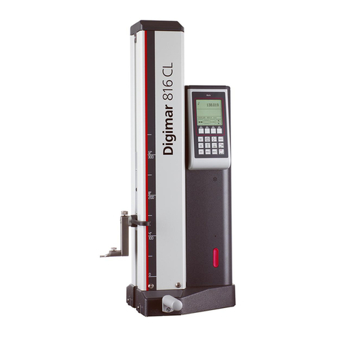
Mahr Digimar 816 CL User manual

Mahr

Mahr Digimar 816 CL User manual

Popular Measuring Instrument manuals by other brands

Hach Polymetron 9586 user manual

Hach

Hach Polymetron 9586 user manual

Xylem WTW Cond 3310 operating manual

Xylem

Xylem WTW Cond 3310 operating manual

Geosense VWPHT-3600 Series instruction manual

Geosense

Geosense VWPHT-3600 Series instruction manual

Wohler FA 320 manual

Wohler

Wohler FA 320 manual

Renkforce 1342395 operating instructions

Renkforce

Renkforce 1342395 operating instructions

LTH Electronics MXD70 Series Configuration guide

LTH Electronics

LTH Electronics MXD70 Series Configuration guide

Meyer Sound SIM 3 Setup guide

Meyer Sound

Meyer Sound SIM 3 Setup guide

Smappee Infinity installation manual

Smappee

Smappee Infinity installation manual

Qtx FRACTAL-250 user manual

Qtx

Qtx FRACTAL-250 user manual

EKO MS-80 quick start guide

EKO

EKO MS-80 quick start guide

Starr Instruments GMX-01 user manual

Starr Instruments

Starr Instruments GMX-01 user manual

VOLTCRAFT SEM6500 CH operating instructions

VOLTCRAFT

VOLTCRAFT SEM6500 CH operating instructions

Turner Designs TD-20/20 Service manual

Turner Designs

Turner Designs TD-20/20 Service manual

QED MP30 instruction manual

QED

QED MP30 instruction manual

Polimaster PM 1703M-O Operation manual

Polimaster

Polimaster PM 1703M-O Operation manual

Leader LV5300 Quick manual

Leader

Leader LV5300 Quick manual

Sekonic LITEMASTER PRO L-478 Series operating manual

Sekonic

Sekonic LITEMASTER PRO L-478 Series operating manual

LSHTEC 86170 user manual

LSHTEC

LSHTEC 86170 user manual

manuals.online logo
manuals.online logoBrands
  • About & Mission
  • Contact us
  • Privacy Policy
  • Terms and Conditions

Copyright 2025 Manuals.Online. All Rights Reserved.