Farmet DUO User manual

OPERATING MANUAL
OILSEED SCREW PRESS
FARMET DUO

OPERATING MANUAL
OILSEED SCREW PRESS FARMET DUO
Page 2of 48

OPERATING MANUAL
OILSEED SCREW PRESS FARMET DUO
Page 3of 48
IMPORTANT
READ CAREFULLY BEFORE USE
KEEP FOR FUTURE REFERENCE
Issued by: Technical Division, Farmet a.s., Jiřinková 276, Česká Skalice 552 03
Number of Pages: 48
Date of Issue: 01/07/2014
Issue Number: 2.2
Changes are reserved

OPERATING MANUAL
OILSEED SCREW PRESS FARMET DUO
Page 4of 48

OPERATING MANUAL
OILSEED SCREW PRESS FARMET DUO
Page 5of 48
Dear Customer,
Farmet DUO Screw Presses are quality products by Farmet a.s. Česká Skalice. You can
fully utilise the advantages and qualities of the Equipment after thoroughly studying the
operating manual.
The serial number of the Equipment is punched on the production label and written in the
operating manual. The Equipment serial number must be stated whenever ordering spare parts
for possible repairs. The production label is located on the basic frame by the gearbox.
Only use spare parts for the Equipment according to the Spare Parts Catalogue officially
issued by the manufacturer, Farmet a.s. Ceska Skalice. The spare parts are identified by a
catalogue number (e.g. LAMELA –2900133).
Possibilities of the Use of Your Equipment
The Farmet DUO screw press is designed for cold-pressing oilseeds, namely rapeseed,
sunflower seeds and other oilseeds. The pressed oil can be used for both technical and food-
processing purposes.

OPERATING MANUAL
OILSEED SCREW PRESS FARMET DUO
Page 6of 48

OPERATING MANUAL
OILSEED SCREW PRESS FARMET DUO
Page 7of 48
Table 1 - Technical Parameters of the Equipment
PARAMETERS
FARMET DUO
3f
FARMET DUO
FM
FARMET DUO
FM 4kW
Machine Length (mm)
780
775
795
Height (mm)
465
540
560
Width (mm)
650
Electromotor Voltage (V)
400
Requirement –
Voltage/Frequency (V/Hz)
3+PE+N,3x230/400V / 50Hz
Rated Output of the
Electrometer (kW)
2.2
3
4
Requirement –Line Protection
(A)
10
16
Press Input Material Parameters
Minimum seed temperature at the press input 15° C,
humidity 5–7 %, quality according to CSN 462300
Noise Level
Equivalent noise level A does not exceed 70 dB, acc. to EN
61672-1:2003
Granule Diameter (mm) –acc.
to the jets
4 (for oilseeds with at least 20 % fat content) 4, 6, 8, 10
Press Head Warming-up to Pre-
actuation Temperature (°C)
60
Press Weight (kg)
115
120
120
Table 1 –Gearbox Parameters
GEARBOX
PARAMETERS
3f
FM
FM 4kW
Type
PSL 100
True Gear
i = 28.2
Input Speed (min-1)
1415
Max. Input Power
(kW)
2.2
3
4
Oil Quantity (L)
2.2
Viscosity Class
VG 220
Oil Type
CLP 220

OPERATING MANUAL
OILSEED SCREW PRESS FARMET DUO
Page 8of 48

OPERATING MANUAL
OILSEED SCREW PRESS FARMET DUO
Page 9of 48
TABLE OF CONTENTS
1. LIMIT PARAMETERS OF THE EQUIPMENT........................................................ 11
2. SAFETY MESSAGES ......................................................................................... 12
3. DESCRIPTION OF THE EQUIPMENT.................................................................. 16
3.1 Terms definition ..................................................................................................... 17
3.2 Optional Equipment ............................................................................................... 18
4. ON-SITE ASSEMBLY AND INSTALLATION OF THE EQUIPMENT.......................... 19
5. ACTIVATION AND SHUTDOWN ....................................................................... 20
5.1 Safety Instructions for the Operator ...................................................................... 20
5.2 Inspection of the Equipment before Activation..................................................... 22
5.3 DUO controls .......................................................................................................... 22
5.4 DUO FM control...................................................................................................... 23
5.5 Activation of the press ........................................................................................... 23
5.5.1 Activating a new press and a press after a long standstill ............................. 23
5.5.2 Activating the press after a standstill under 5 minutes ................................. 24
5.6 Shut-down of the press .......................................................................................... 24
5.6.1 Shut-down of the press for a short period of time (under 5 minutes) .......... 24
5.6.2 Shut-down of the press for a longer period of time (more than 5 minutes) . 24
6. OPERATION OF THE EQUIPMENT .................................................................... 25
6.1 Inspection of the Operating Values and Parameters ............................................. 25
6.2 Breakdown ............................................................................................................. 25
6.3 SUDDEN STOP of the PRESS ................................................................................... 25
6.4 “OILING UP” THE PRESS.......................................................................................... 26
6.5 Operating Diary ...................................................................................................... 26
7. ADJUSTING OPERATING MECHANISMS........................................................... 27
7.1 ADJUSTING THE OPERATING PARTS OF the EQUIPMENT...................................... 27
8. OPERATING DEFECTS...................................................................................... 29
9. MAINTENANCE AND REPAIRS OF THE EQUIPMENT ......................................... 30
9.1 General Instructions ............................................................................................... 30
9.2 List of Recommended Tools for Regular Maintenance and Operation ................. 31
9.3 Maintenance of the Equipment ............................................................................. 31
9.4 Regular Maintenance and Repairs ......................................................................... 32
9.4.1 Lubrication Plan .............................................................................................. 33

OPERATING MANUAL
OILSEED SCREW PRESS FARMET DUO
Page 10 of 48
9.4.2 Gearbox Maintenance and Operation............................................................ 33
9.5 Disassembly and Assembly of the Equipment Parts .............................................. 34
9.5.1 Disassembly and Assembly of Press Components ......................................... 35
9.5.2 Assembly of Press Components ..................................................................... 36
9.6 Assessing the Deterioration of the Operating Mechanisms of the Equipment..... 36
10. DISPOSAL OF THE MACHINE, PROTECTION OF THE ENVIRONMENT ................. 37
11. SERVICE AND GUARANTEE TERMS .................................................................. 38
11.1 Service ................................................................................................................ 38
11.2 Guarantee........................................................................................................... 38
12. ANNEXES........................................................................................................ 41

OPERATING MANUAL
OILSEED SCREW PRESS FARMET DUO
Page 11 of 48
1. LIMIT PARAMETERS OF THE EQUIPMENT
The Equipment is designed to be operated in interiors with ambient temperature from
+15 °C to +35 °C and relative humidity from 10 % to 90 % without condensation.
The Equipment is designed for continuous operation with periodical inspections and
regularly performed maintenance.
The Equipment is designed for continuous operation with periodical inspections and
regularly performed maintenance.
The Operator must not use the equipment for any other purposes, especially for pressing
other seeds than oilseeds or other materials.
OPERATING MANUAL
OILSEED SCREW PRESS FARMET DUO
Page 12 of 48
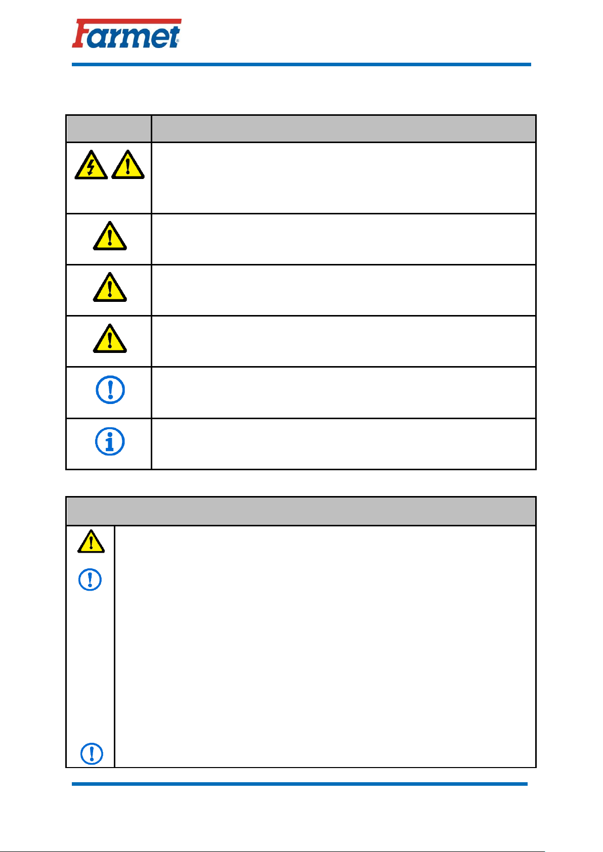
2. SAFETY MESSAGES
Symbol
Meaning
The general warning symbol identifies important information regarding the
safety instructions in the instruction manual and safety signs on your
machine. If you see this warning sign, be aware that there is a risk of injury
which may cause death. Instructions labeled this general warning sign must
always be observed.
Danger! This warning sign warns about an immediate dangerous situation
ending with death or severe injury.
Warning! This warning sign warns about a dangerous situation ending with
death or severe injury.
Caution! This warning sign warns about a situation that may end with a
smaller or slight injury. It also warns about dangerous actions related to the
activity that could lead to an injury.
The symbol indicates an important instruction, feature or procedure that is
required to meet during installation, use and maintenance of equipment.
Failure to comply may result in equipment damage.
Symbol indicates useful information related to equipment.
A. GENERAL INSTRUCTIONS FOR USE
A.1 The Operator must get acquainted with the Equipment, its function and
control elements prior to its first use.
A.2 The Equipment may only be operated by a person authorized by the Owner
under the following conditions:
The Operator must be demonstrably informed of the safety regulations for
the operation of the Equipment and the operation of the technological unit in
which it is installed and must be practically able to control the operation of
the Equipment.
The Equipment must not be operated by a minor (person below 18 years of
age).
The Operator must know the meaning of the safety signs placed on the
Equipment. The safety signs must be respected to ensure a safe and reliable
operation.
A.3 Maintenance and servicing repairs on the Equipment may only be performed

OPERATING MANUAL
OILSEED SCREW PRESS FARMET DUO
Page 13 of 48
by a person:
Authorised by the Owner
Educated in the machinery field with knowledge of repairs of similar
equipment
Demonstrably acquainted with safety regulations for work with the
Equipment
A.4 The Operator must secure the safety of other persons when working with the
Equipment.
A.5 The Operator may only enter the Equipment structure when the Equipment
is in standstill and only for the following reasons:
Adjustment of the working parts of the Equipment
Repair and maintenance of the Equipment
A.6 Any changes or modifications of the Equipment may only be performed with
written consent of the Producer. The Producer bears no liability for any potential
damage incurred due to the failure to observe this instruction. All warning and
safety signs must be legible and in their places. In case of damage or loss, these
signs must be immediately renewed.
A.7 The Operator must have the Operating Manual with the work safety
requirements available at any time when working with the Equipment.
A.8 The Operator must not consume alcohol, medicines, narcotic and
hallucinogenic substances that reduce attention and coordination capabilities while
using the Equipment. If the Operator must use medicines prescribed by a physician
or uses over-the-counter medicines, he must be informed by a physician, whether he
is capable of a responsible and safe operation of the Equipment under such
circumstances.
A.9 The Equipment may be activated provided that it is technically fit and
complies with regulations for safety and hygiene at work and provided that it is
used in compliance with the terms and conditions specified by the Producer.
A.10 When working with the Equipment, follow the instructions in this
Operating Manual as well as generally binding regulations for safety at work,
protection of health, fire and traffic safety and protection of the environment.
A.11 Do not use water to extinguish fire of electric equipment. In case of fire,
follow the valid fire regulations.

OPERATING MANUAL
OILSEED SCREW PRESS FARMET DUO
Page 14 of 48
B. TRANSPORTING THE EQUIPMENT
B.1 The vehicle intended for the transportation of the Equipment must have at
least the same bearing capacity as the weight of the transported Equipment is. The
total weight of the Equipment is stated on the nameplate.
B.2 The dimensions of the transported Equipment including the vehicle must
comply with valid acts and regulations, e.g. Decree No. 102/1995 for road
transportation.
B.3 The transported Equipment must be always attached to the vehicle so that it
cannot be released during transportation.
B.4 The carrier is liable for damages caused by the release of incorrectly or
insufficiently attached Equipment to the vehicle.
C. MANIPULATING THE EQUIPMENT BY A LIFTING DEVICE
C.1 The lifting device and binding instruments intended for manipulation with
the Equipment must have at least the same bearing capacity as the weight of the
manipulated Equipment is.
C.2 The Equipment may only be attached for manipulation in designated places
marked by stick-on labels showing a “chain”.
C.3 When attached (suspended) in designated places, it is not allowed to move in
the area of a potential reach of the manipulated Equipment.
D. WORK SAFETY LABELS
The warning safety labels are used for the Operator’s protection.
The following applies generally:
Strictly observe the warning safety labels.
All safety instructions also apply to other users.
If the aforementioned “SAFETY LABEL” located on the Equipment is
damaged or destroyed, THE OPERATOR MUST REPLACE IT WITH A
NEW ONE!!!
The position, appearance and exact meaning of work safety labels on the
Equipment are given in the following table (Table 2) and picture (Figure 1,
Figure 2).
OPERATING MANUAL
OILSEED SCREW PRESS FARMET DUO
Page 15 of 48
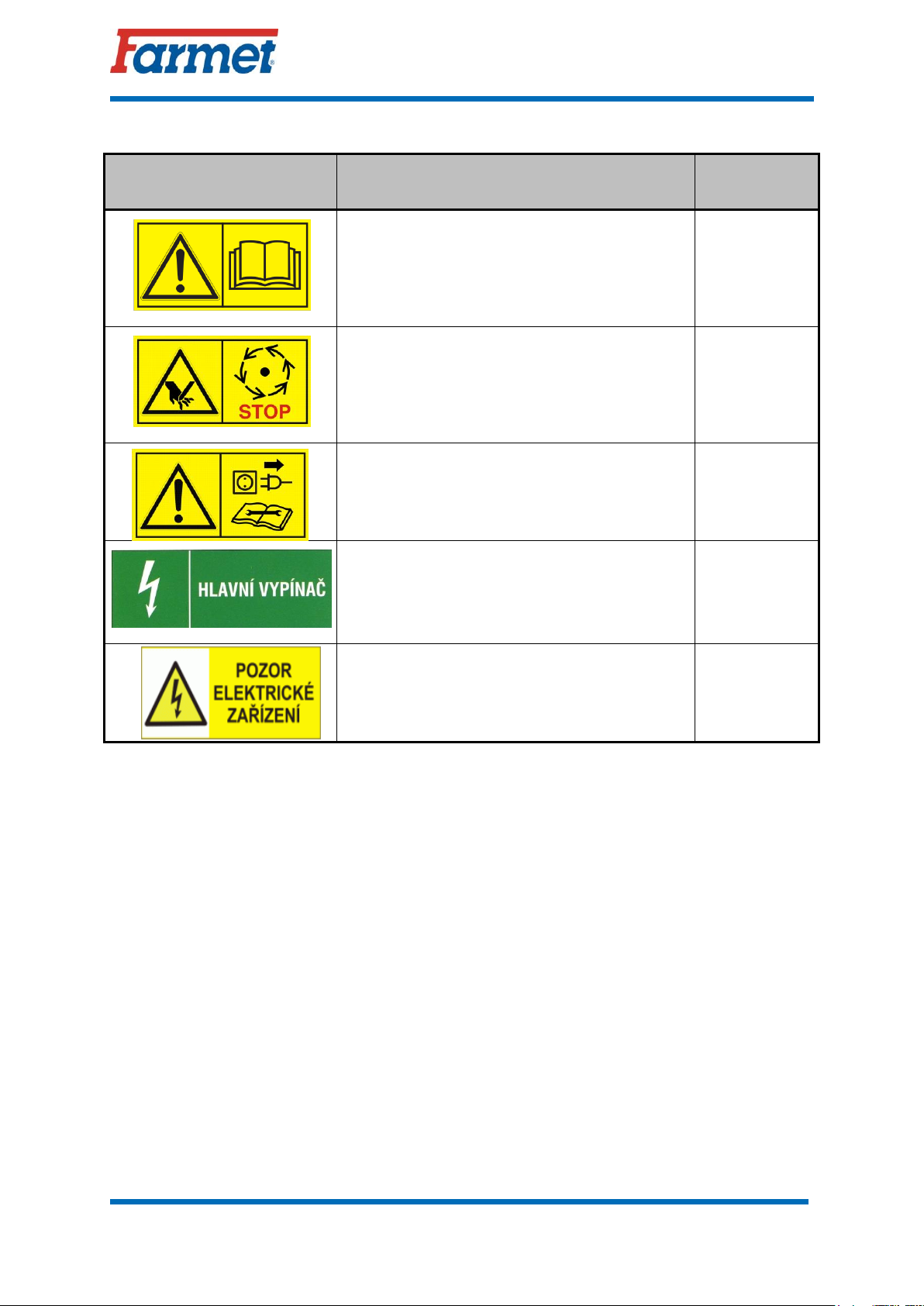
Table 2 –Warning Safety Labels
WARNING SAFETY LABEL
TEXT TO THE LABEL
POSITION ON
THE MACHINE
Read the Operating Manual carefully prior
to manipulation with the Equipment.
Observe the instructions and safety rules
when operating the Equipment.
P 1 H
Do not enter the area of the moving screw
unless the machine is standstill and the motor
is switched off.
P 24 H
The Equipment must be disconnected from
the power supply during repairs and
maintenance or when welding is performed on
the Equipment.
P 47 H
Main switch
P HV
Warning! Electrical device
P PEZ
OPERATING MANUAL
OILSEED SCREW PRESS FARMET DUO
Page 16 of 48
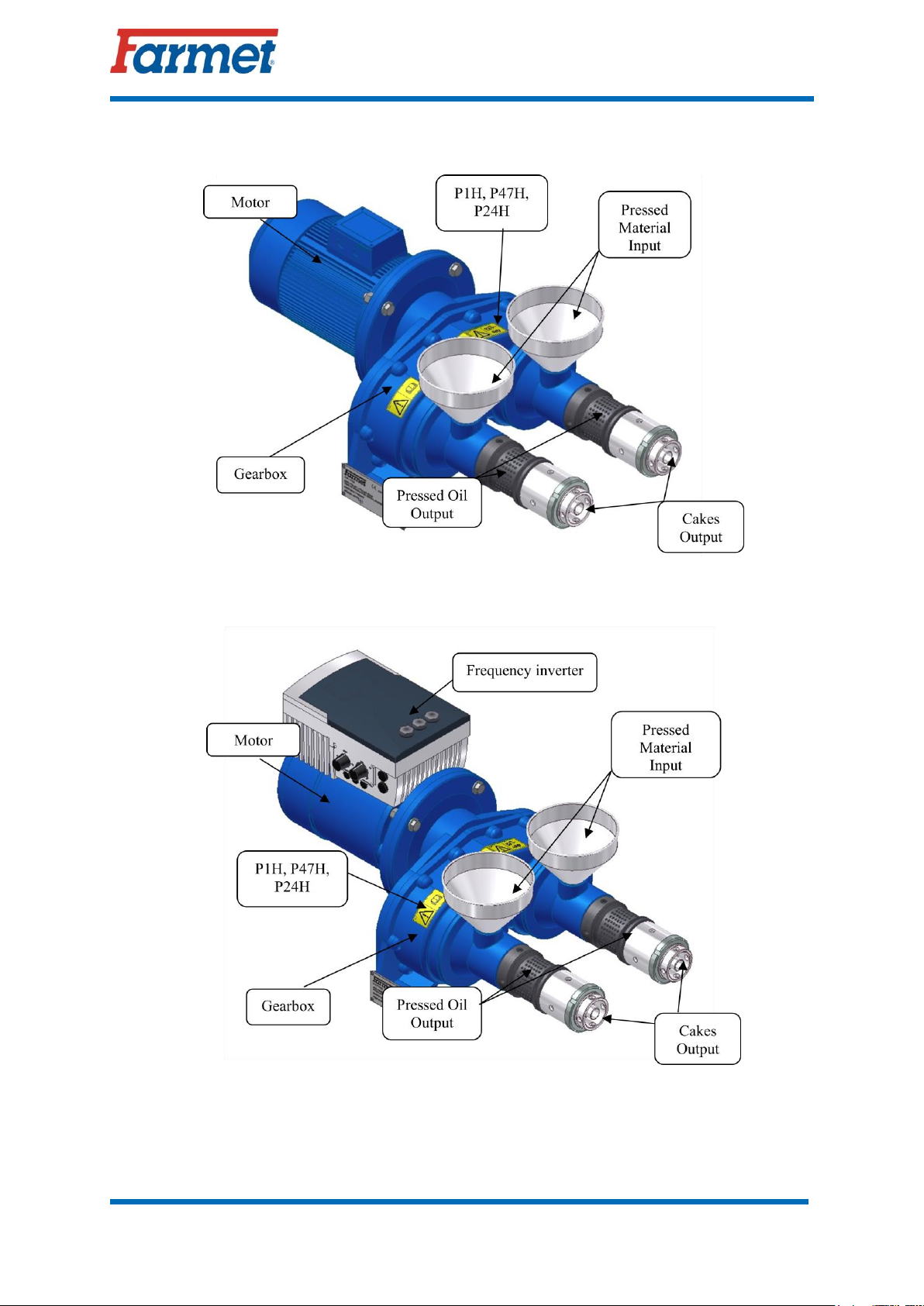
3. DESCRIPTION OF THE EQUIPMENT
Figure 1 –DUO
Figure 2 - DUO FM

OPERATING MANUAL
OILSEED SCREW PRESS FARMET DUO
Page 17 of 48
The pressing unit consists of an aluminium hopper, a press screw, a die, a heating sleeve
nut, a nozzle holder, a nozzle for cakes and a heating sleeve.
Press Description
The presses can be assembled into batteries placed on one pedestal with a joint discharge
chute and a belt conveyor for carrying away the pressed cakes in the form of granules. Each
press has two press heads, two press screws, two dies, driven by one gearbox and one
electromotor.
Press Gearbox Description
It is a wet-operation gearbox; it is a single reduction gearbox for the operation of two
screws of one press, designed as a compact mono-block. The box is a casting with a bottom;
bearings: conical (ISO 355 –7FB corresponds with 31310), ball (6306).
The output hollow shafts of the gearbox are designed to be inserted into the press screw.
The shafts are sealed with Gufero shaft seal. The gearbox is lubricated by wading wheels in
an oil bath and oil spray inside the box.
Press Function Description
The oilseeds are brought into the hopper. This may be solved either by a standpipe from a
higher floor of the building or by a separate container above the press or above the press
battery. When the electromotor is activated, the seeds from the hopper are collected by the
screw that presses the seeds into the head (nozzle holder) in the place of the perforated die
which presses out oil that runs down into the chute (not included in the delivery). The pressed
cakes go through the nozzle where they are pressed to come out in the form of granules.
When actuating the press, the pressing mechanism must be heated to the temperature of 60°C.
Use the heating sleeve (optional accessory).
3.1 TERMS DEFINITION
Oilseed (seed, oil seed) –a common crop seed containing vegetable oil, prepared (i.e.
cleaned and dried) for storage under the local conditions of the seed species
Cake –remaining oilseed material after oil pressing
Vegetable oil –oil obtained from oilseeds or by chemical extraction
Crude oil –vegetable oil after pressing (or extraction) and filtration without any other
treatment (filtered oil)
Oil pressing –pressing oil from oilseeds by mechanical force –pressure
Screw press (for oilseeds) –equipment for pressing oil by creating pressure using a
rotating screw with variable geometry in a closed perforated filter (also called the bin)
Oil separation –separation of gross mechanical impurities from oil
Oil filtration –separation of mechanical impurities from oil (particles)

OPERATING MANUAL
OILSEED SCREW PRESS FARMET DUO
Page 18 of 48
Press capacity –the quantity of the pressed material entering the press per unit of time,
usually stated in kilograms per hour
3.2 OPTIONAL EQUIPMENT
Electrical Equipment with Frequency Convertor
The frequency convertor is installed directly on the motor terminal block. There are control
buttons on the frequency convertor for switching on and controlling the motor revolutions.
More information is available in the NORDAC SK 205E Frequency Convertor Operating
Instructions.
Electrical Equipment without Frequency Convertor
The electromotor starter allows starting and stopping the motor (including emergency
stop).
Heating Sleeve
It warms up the die before the actuation of the press to ensure better start-up.
Heating sleeve with temperature regulation
It allows heating and stabilization of the temperature of pressing device to the desired
temperature.
Wooden Pedestal under the Press
The pedestal under the press is made from solid stained timber. It stabilizes the press
during operation.
Table under the Press
The metal pedestal under the press ensures stability during operation.
Service Tools
Tools required for disassembling and cleaning the press. It contains a hook spanner, a box
spanner and a cleaning preparation.
Hopper above the Press with Capacity of 20L
A metal hopper above the DUO screw press with the capacity of 20 litres. It is an extension
above two hoppers that are included in the pressing mechanism.

OPERATING MANUAL
OILSEED SCREW PRESS FARMET DUO
Page 19 of 48
4. ON-SITE ASSEMBLY AND INSTALLATION OF THE
EQUIPMENT
The Owner must perform the assembly according to the instructions of the Producer,
best in cooperation with an expert servicing technician assigned by the Producer.
The Owner must secure a functional test of all assembled parts after the completion of
the Equipment assembly.
The wiring must be executed in compliance with valid standards and documented by a
revision. Any repairs, modifications and other work on the wiring may only be
performed by authorized persons with corresponding electrical qualifications.
The spatial organization of the pressing shop must ensure free access to the Equipment
so that it is possible to perform its maintenance and service without any difficulties.
If more than one piece of equipment is installed in the pressing shop, make sure that
the individual control elements, boxes and equipment are clearly and visibly marked so
that there is no confusion in case an emergency stop is required.
When the Equipment is installed, it has to be properly levelled into a horizontal
position using spacers that do not increase the surface pressure from the supporting leg
so that the Equipment is not twisted or distorted; use suitable base wedge blocks. If the
Equipment is attached to a steel structure together with other heavy appliances, make
sure that the other appliances are installed on the structure prior to the final levelling
using a water level.
When installing the Equipment, make sure that the Equipment is accessible for the
purpose of maintenance and oil change (access to the outlet and inlet openings, oil
level gauges, air release plugs and sight holes).
The Equipment may be installed on a floor with the bearing capacity specified in the
project.
The Equipment is oriented according to the technological disposition.
Make sure that there are tools available. It is also suitable to provide all other
equipment required for maintenance, such as various hand tools, crowbars and lifting
devices.
Check the direction of turning for all rotary devices.
The wiring circuit is included in the annex to this manual.

OPERATING MANUAL
OILSEED SCREW PRESS FARMET DUO
Page 20 of 48
5. ACTIVATION AND SHUTDOWN
5.1 SAFETY INSTRUCTIONS FOR THE OPERATOR
The Operator must not:
Activate or use the Equipment when the covers are removed or damaged
Touch the moving parts of the Equipment
Work with the Equipment when the working area of the Equipment and the
workstation are not sufficiently illuminated
Perform the maintenance, cleaning, repairs and adjustments of the Equipment
when in operation
Discard and remove safety protective and locking devices
Take off or remove the covers unless the machine is in complete standstill and the
shutdown condition has been secured
Remove the aluminium hopper from a press that has not been switched off and
from a press in operation
Insert limbs into the hopper and the gap created by removing the hopper
Connect the equipment to a power supply with damaged cables or damaged
distributor covers
The Operator must get acquainted with the Equipment, its function and control
elements prior to its first use.
The Operator must check the Equipment with regard to its completeness, work safety,
work hygiene, fire safety, traffic safety and protection of the environment prior to each
use (activation after a shutdown).
The Operator is responsible for the safety and all damages caused by the operation of
the Equipment.
The Operator must observe the technical and safety regulations for the Equipment
specified by the Producer.
The Operator must prevent unauthorized access to the rotary parts of the Equipment.
Check the condition of the Equipment prior to its activation. It is forbidden to active
the Equipment when showing signs of damage.
It is required to use working clothes, gloves, shoes with anti-slip soles and protective
goggles when operating the Equipment.
It is recommended to use anti-noise protectors when moving around the pressing shop.
It is a workplace with periodical supervision and operation.
Table of contents
Popular Power Tools manuals by other brands

Powermatic
Powermatic 29 Instruction manual and parts list

medical bees
medical bees F-31 Series user manual

Parkside
Parkside PMGS 12 D3 Translation of the original instructions

Parkside
Parkside PDSP 1000 D5 Operation and safety notes translation of the original instructions

DeWalt
DeWalt DCST972 instruction manual

Parkside
Parkside PSFS 250 A1 Original instructions


Hitachi
Hitachi WR 12DAF Handling instructions

Hitachi
Hitachi C 6DC2 Safety and instruction manual

iBell
iBell JS10-70 Operator's manual

Parkside
Parkside POF 1200 D3 Translation of the original instructions

Hilti
Hilti TE 75 operating instructions

TYROLIT Hydrostress
TYROLIT Hydrostress DME19DPP Instruction manuals