FARMTECH FPD 30 User manual

WARNING: Read power down operation before use

1
CONTENTS....
Description Page
Contents 1
Introduction 2
Specifications 3
Safety Information 4 & 5
Operation -
Attaching to the tractor - initial assembly 6
Standard models 6
Hydraulic model 6
Connecting hydraulic hoses 7
Attaching Gearbox & Auger (all models) 7
Connecting PTO shaft (all models) 7
Detaching digger from Tractor 8
Attaching assembled digger to the Tractor 8
Changing the Auger 8
Changing the auger teeth and pilot 8
Adjusting slip clutch 9
General operation 10
Transporting 10
Lubrication and Maintenance 11
Power Down operation 12
Warranty 13

2
TO THE OWNER
Congratulations on the purchase of your new Post Hole Digger.
Your new Post Hole Digger is designed to meet your agricultural requirements. The ease of
operation and low maintenance will give you many trouble free hours of
operation.
Make certain that you read and understand the important instructions for the
adjustments, operation and the maintenance contained in this manual. If there are any
instructions which you do not fully understand, contact your Dealer for
clarification prior to using the unit.
When in need of replacement parts, specify the model and serial number of your Post Hole
Digger.
To give you many years of service, regular preventative maintenance should be
performed, ie lubricate bearings, touch up painted areas susceptible to rust and
corrosion, and store implement in a dry place in off-season when not in use.
We wish you many years of profitable use from our equipment.
Introduction ...
Farm Tech is an Australian owned and family operated company. We first started
manufacturing in 1976. Our company has an excellent production plant in Wodonga, set up
to specialize in the design and manufacture of post hole diggers, slashers,
toppers, soil aerators, grader blades, carryalls and other related products. We have a
proven track record of supplying quality products made to your specification. Buying a
locally manufactured product, you can be assured of after sales service—second to none.
This manual covers all models of Farm Tech 3PL, tractor mounted, PTO driven post hole
diggers, including the 50HP, 75HP and 75HP hydraulic power down models.
The Farm Tech post hole diggers are designed and manufactured to provide a high
standard of performance and safety. To ensure continued safe and efficient operation of
your post hole digger, you need to read this manual thoroughly and fully familiarize yourself
with all aspects of the machine’s operation, maintenance and safety
procedures.
Because of the unguarded auger, all post hole diggers are inherently dangerous
machines. For this reason pay particular attention to the safety instructions
contained within this manual.

3
Specifications
Mainframe
Welded RHS steel construction.
Removable lower linkage pins
50 HP Model - Category 1
All Other Models - Category 2
Driveline
Fully shielded telescopic PTO shaft.
Overload protection -
Adjustable twin disc spring loaded friction clutch
(6 in. dia. on 50 HP, 8 in. dia. on 75 HP)
Flexible safety shield over clutch or shear bolt. Cast iron gearbox with heat treated
bevel gears and shafts.
Gearbox lubrication SAE 85-90 gear oil.
Augers
Interchangeable augers with welded steel flights and forged steel boring head.
Replaceable forged steel teeth and pilot bit.
Flat or chisel teeth, plain or tungsten tipped.
Plain or tungsten tipped pilot bit. Digging depth 1 metre.
Auger Digger Model
50HP 75HP
Diameter
6 inch X X
9 inch X X
12 inch X X
15 inch X
18 inch X
20 inch X
24 inch X
HYDRAULICS (75 HP HYDRAULIC MODEL)
Double acting cylinder 3” dia. X 8” stroke. Two hydraulic hoses with quick release
fittings
Farm Tech Machinery (hereafter known as FTM) welcomes any warranty repair
and apologises for any inconvenience. See the last page for the express warranty
coverage offered. The following information will assist your understanding of
warranty procedures.
Any authorised FTM dealer service outlet can perform warranty. Repairs for you,
however, we recommend that such repairs be carried out by the Dealer from
whom you bought the product.
Most warranty repairs are handled routinely, but sometimes requests cannot be
accepted under warranty, normal wear and tear is not covered by warranty nor
does warranty apply if a product failure can be attributed to abuse or neglect.
Whilst FTM will abide by its warranty policy under all genuine circumstances, we
must emphasise that such can only apply when our equipment has been used in
applications for which it was designed and manufactured and that a reasonable
degree of care and common sense has been exercised by the operator.
To avoid misunderstandings, which might occur between the customer and the
service outlet, items subject to normal wear and tear such as augers teeth or
similar ground engaging items are not covered under warranty.

4
x FTM post hole diggers are designed and
manufactured solely for the purpose of bor-
ing holes earth and clay materials. Under
no circumstances should they be used for
any other purpose.
x Before using the post hole digger carefully
read and ensure you understand the con-
tents of this manual and the contents of the
operators manual for the associated tractor,
including all relevant safety instructions.
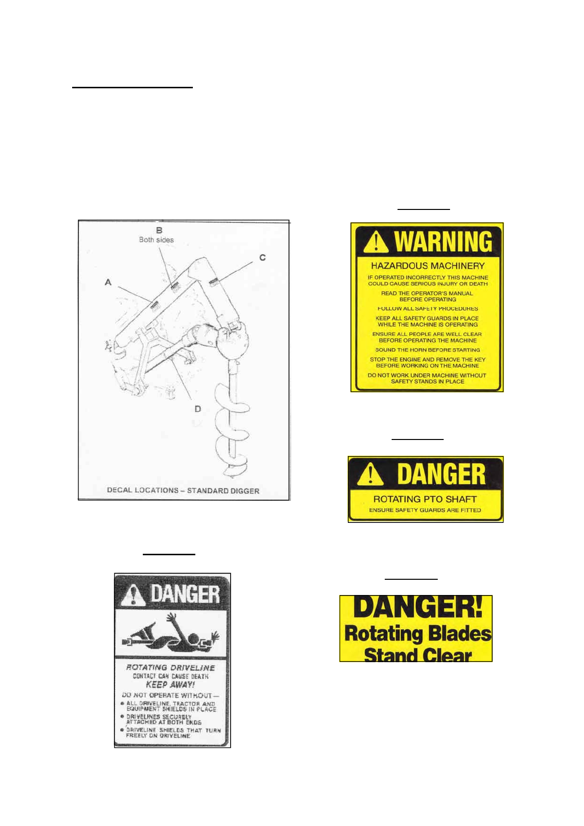
x Before operating the post hole digger read
all the safety warnings that are carried on
the machine. Refer to the next page for the
location and the wording of these warnings.
x Never allow an inadequately trained person
to attach or operate the post hole digger.
x Do not operate the post hole digger whilst
wearing loose clothing, unrestrained long
hair, jewelery or anything which could be-
come entangled in rotating parts or limit
your vision.
x Only operate the post hole digger on a trac-
tor fitted with a roll-over protective structure
(ROPS), or a cab incorporating a ROPS,
complying with AS1636 or equivalent.
x Wear ear protection when operating the
post hole digger on a tractor that is not fitted
with a sound proofed cabin.
x Ensure that the tractor engine power and
linkage capacity match the requirements of
the post hole digger. Refer to the tractor
operator’s manual for safe working loads,
including any counter-weighting that may be
required to balance the weight of the post
hole digger.
x Do not operate the post hole digger without
all its safety shields and the tractor safety
shields in place.
x Before operating the post hole digger in-
spect the area to be worked to ensure that
you are familiar with the ground conditions.
x Ensure that there are no underground elec-
trical cables, telephone cables, gas, water,
sewerage or drainage pipes in the area to
be drilled. If in doubt about any of the
above do not start digging until the circum-
stances have been fully investigated and it
is safe to begin.
x Exercise extreme care when operating in
wet or slippery conditions or on sloping or
uneven terrain. Allow for the effect that
the weight of the post hole digger has on
the tractor’s stability. Refer also to the
tractor manufacturer’s operating and
safety instructions.
x Do not operate the post hole digger with
people or animals in the vicinity where
they could be caught in the mechanism
or injured by the machine. Keep onlook-
ers at least 6 metres from the digger
whilst in operation.
x Always operate the post hole digger from
the tractor seat.
x Never clear earth away from the auger
whilst it is operating or allow any helper
to do so.
x Never allow a person to pull down on the
digger boom or attach any type of coun-
terweight to the boom to increase pene-
tration.
x Before dismounting from the tractor or
allowing any person to approach the post
hole digger, disengage the PTO, switch
off the tractor engine and apply the park-
ing brake.
x Ensure the tractor engine is switched off
and the parking brake is applied before
performing any inspection or mainte-
nance on the digger. If it is necessary to
raise the machine for such work ensure it
is properly supported. Do not rely on the
tractor hydraulics for support.
x Never allow any person to ride on the
post hole digger or the tractor when the
digger is attached.
x Relieve all hydraulic pressure before dis-
connecting hoses on hydraulic diggers.
Oil escaping under pressure can pene-
trate the skin, causing serious injury.
Seek medical advice immediately if in-
jured by escaping oil.
Whilst your FTM post hole digger has been designed and manufactured to incorporate all necessary
safety features it is essential that any person who operates or works on the machine is aware of the
safety precautions that should be exercised.
Before operating the post hole digger read the following safety instructions.
Failure to comply with these warnings may result in serious injury or death.

5
DECAL A
DECAL B
DECAL D
DECAL C
Safety Information
Locations of Safety Warnings
The location and wording of the safety decals fitted to all FTM post hole diggers is shown below.
It is important that all operators read and follow the information given on the decals. They should be
kept clean and legible at all times. If any are missing or unreadable they should be replaced by
ordering new decals from your dealer.

6
Operation
Attaching to the Tractor - Initial Assembly
1. Standard Models
Position the linkage frame of the digger behind
the tractor. Disable the tractor draft control
mechanism, fully lower the tractor linkage arms
and connect the digger linkage pins. Install a
Lynch pin in each linkage pin to secure the arms.
Fit the inner end of the boom into the upper
linkage clevis of the tractor, install the tractor
linkage pin and secure it with a Lynch pin.
While supporting the boom, swing the digger
frame up so that the connecting bolt can be
installed in the boom bracket. Tighten the locknut
on the connecting bolt so the fit is snug but free to
pivot. Three holes are provided in the bracket to
facilitate fitment to different tractors. Use the hole
that positions the linkage frame nearest to
vertical.
If necessary adjust the sway chains on the tractor
linkage to centralize the digger and prevent any
sideways movement.
Refer to the next page for information on fitting
the gearbox pivot pin and PTO shaft.
2. Hydraulic Model
At the time of delivery the linkage frame with
boom attached, PTO shaft, hydraulic cylinder with
hoses connected, and gearbox with auger
attached are supplied as separate items. The
following instructions apply for the first
installation.
The Hydraulic digger is fitted with bolt-on
Category 2 linkage pins. If it is necessary to fit it
to a Category 1 tractor, change the pins to
Category 1 and use a spacer in the pin hole of
the upper hitch post to reduce its diameter.
Category 1 pins and spacers are available from
FTM dealers. The upper linkage pin and three
Lynch pins from the tractor are required to
complete the installation.
Place the linkage frame and boom assembly
behind the tractor. Disable the tractor draft
control and lower the linkage arms so they can be
fitted over the digger linkage pins. If necessary
reposition the pins to a more convenient height.
Fit a Lynch pin in each linkage pin to secure the
arms.
Remove the locking bolt from the upper hitch post
and swing the linkage frame up so the rear
member is vertical. Adjust the length of the hitch
post (to the nearest hole) so it can be fitted into
the tractor upper linkage clevis. Refit the locking
bolt and nut to the hitch post. Install the upper
linkage pin and secure with a Lynch pin. It may
be necessary to adjust the height of the tractor
arms so the holes align to enable installation of
the upper pin.

7
Operation
Once the Hydraulic digger is fitted to the tractor the linkage must be placed in the float position with
the draft control disengaged so the digger height is then controlled by the hydraulic cylinder.
If necessary adjust the sway chains on the tractor linkage to centralize the sub-frame and prevent
any sideways movement.
Install the hydraulic cylinder between the lugs on the linkage frame and boom using the pins
supplied. Connect the hoses to the tractor, see below for the further details.
Connecting the Hoses - Hydraulic Model
Before attaching or removing the hydraulic hoses ensure that the quick release connections are
clean to avoid contaminating the system.
Plug the digger hoses into the tractor remote outlets. For safety reasons it is desirable to always fit
the hoses in the same pattern to ensure that the direction of the control to apply downward pressure
will always be the same. This can be achieved by marking the hoses with tags. Ensure the hoses
are well supported and clear of the tractor wheels.
Attaching the Gearbox and Auger - All Models
Lower the digger boom fully. Position the gearbox an auger assembly behind the boom and align the
pivot pin holes. Install the pivot pin and secure with the split pin provided. Make sure that the input
shaft of the gearbox is facing towards the tractor, so that the PTO shaft can be fitted.
Raise the boom to full height to allow the auger to hang vertically then lower it so the end of the
auger rests on the ground.
Connecting the PTO Shaft - All Models
Clean and grease the splines on the tractor and digger PTO stub shafts and install the PTO shaft
making sure that the spring loaded locking pins engage in the grooves of both stub shafts.
Ensure that the PTO stub shaft guard is fitted to the tractor.
Check that the PTO shaft is of the correct length, as follows. On Standard digger models set the
linkage so the ends of the two stub shafts are closest. Install the PTO shaft then depress the locking
pin at the gearbox end and pull the shaft back to check there is at least 25mm of telescopic travel
remaining. Refit the PTO shaft and raise and lower the digger to check that the telescopic tubes
overlap by approximately1/3rd their length, and not less than 150mm, in all positions. On the
Hydraulic model check these dimensions in the fixed operating position. Refer diagram below.
If the PTO shaft has to be shortened cut equal amounts from both male and female shafts and safety
covers. Carefully remove all burrs then clean and relubricate before reassembling.
Relieve all hydraulic pressure before connecting or disconnecting hoses. Oil
escaping under pressure can penetrate skin, causing serious injury. Seek
immediate medical treatment if injured by escaping oil.

8
Operation
Detaching the Digger from the Tractor
Raise the boom to allow the auger to hang
vertically then lower it until the end rests on the
ground. Remove the PTO shaft and on hydraulic
diggers disconnect the hydraulic hoses. Move
the tractor slowly forward whilst lowering the
boom until the digger gearbox rests on the
ground. Stop the tractor and fully lower the
linkage. Disconnect the upper linkage pin then
the lower pins. It may be necessary to use a
hoist to take the weight of the digger.
Alternatively the digger can be removed with the
PTO still attached to the gearbox by drilling the
auger into the ground.
Attaching Assembled Digger to the Tractor
Position the digger with the PTO shaft removed
and gearbox and auger on the ground behind the
boom. Back the tractor into position, disable the
draft control and lower the linkage. Connect the
tractor arms to the digger pins, swing the digger
frame up and fit the boom on the tractor upper
hitch clevis, or connect the hitch post on a
hydraulic digger. Install the PTO shaft. Connect
the hydraulic hoses, if applicable.
Changing the Auger
Interchangeable augers of various diameters are
available for all post hole diggers. Augers have
double cutting teeth and range from 4 to 14
inches in diameter. Refer to the Specifications
section for the list of auger diameters available for
each model. All augers are of the same length
and are attached in the same way by two bolts
through the gearbox output shaft.
To remove the auger, raise the boom to allow the
auger to hang vertically then lower until the end of
the auger is about 100mm above the ground.
Stop the tractor engine and apply the parking
brake. Remove the two attaching bolts from the
upper end of the auger and pull down so that it
slides off the gearbox shaft. If the auger is tight
on the shaft loosen it by sharply striking the auger
tube with a hammer where it overlaps the
gearbox shaft. If it is necessary to strike the
auger longitudinally on the flighting to drive it off
the shaft place a piece of timber on the flighting to
avoid damage.
Clean and lightly grease the gearbox output shaft
and the inner tube of the new auger. Align the
bolt holes and slide the auger onto the gearbox
shaft. Install and securely tighten the two
attaching bolts.
Changing Auger Teeth and Pilot
When worn the teeth and/or pilot bit on the auger
head should be replaced to maintain good
digging performance. Two types of teeth are
available and both can be supplied as plain
forgings or with tungsten carbide tips for longer
life. Flat teeth are used for normal ground
conditions. Chisel teeth can be fitted for drilling in
rocky ground. Tungsten tipped teeth provide long
life in abrasive conditions but can become
chipped if used in very rocky conditions. Plain or
tungsten carbide tipped pilot bits are also
available. The same teeth and pilots fit all
augers.
When fitting chisel teeth to double toothed augers
it is normal to only fit chisels to the inner position
and retain the flat teeth in the outer position.
Chisels are rarely required in both positions.
The teeth are located in the socket of the auger
head by their U-shaped profile and are held in
place by a rubber retainer which is wedged
between the tooth and the socket. To remove the
tooth, place a small punch on the rear corner and
strike sharply with a hammer to drive it out of the
socket, refer diagram below.

9
Operation
Always fit new teeth in pairs and use new retaining rubbers. Teeth and rubbers are sold in sets.
Push the rubber through the hole in the socket and position it centrally. Align the U-shape of the
tooth with the socket and hammer it into position with a soft-headed hammer, or place a piece of
timber between the hammer and tooth.
The pilot bit is located on the stub of the auger head and is driven by an interlocking tongue and slot.
A single bolt and locknut secure it.
Adjusting the Slip Clutch
50 and 75 H.P Model Post Hole Diggers are fitted with an adjustable friction clutch, which slips under
heavy load to prevent damage to the auger or driveline, such as when encountering rocks or heavy
tree roots.
The slip clutch is factory set and should not need adjusting under normal use. If it is necessary to
adjust the clutch, remove the PTO shaft and turn each of the nuts on the clutch spring bolts by one
half turn. Turning the nuts clockwise increases spring loading and reduces clutch slip. Turning the
nuts anti-clockwise loosens the clutch.
After adjusting the clutch, operate the digger and check whether slipping continues. It is important
that adjustment is made evenly and in small increments. Over-tightening may result in damage to
the PTO shaft, gearbox or auger, so care needs to be taken. Under no circumstances should the
post hole digger be operated with the clutch tightened to an extent where it is locked.
If the post hole digger has not been used for some time and the clutch cannot be made to slip, it may
be seized due to sticking plates. In this case, fully slacken each of the clutch bolts and run the digger
for about 30 seconds with the auger in the ground to free the clutch plates and clean the surfaces.
Then re-tighten the spring bolts evenly to achieve the required slip setting.

10
Operation
General Operation
Before operating the digger for the first time carry out the lubrication checks shown in the Lubrication
and Maintenance section. Read all the safety information contained in the manual and on the decals
attached to the machine. Carefully inspect the area to be dug.
Position the tractor with the auger hanging vertical and touching the ground at the spot where the
hole is to be dug. Use the tractor linkage to raise or lower the digger boom on Standard models. On
the Hydraulic model use the hydraulic cylinder to raise or lower the boom.
Disengage the tractor draft control and set the linkage to the FLOAT position, raise tractor engine
speed to a fast idle so that the auger will revolve in the range of 50 to 100rpm. The most appropriate
auger speed will depend upon the available tractor power, the diameter of the auger and the ground
conditions. The larger the
diameter of the auger the slower the speed should be.
Engage the PTO drive and allow the action of the auger to penetrate the surface.
On Standard models, slowly lower the tractor linkage to follow the penetration of the auger.
On the Hydraulic model ensure linkage is in float before applying down-pressure with the hydraulic
cylinder to increase penetration but limit the pressure to ensure that the tractor wheels are not lifted
off the ground.
At every 300 to 500mm of depth lift the boom to spin the earth off the auger flighting, then continue
drilling. When raising or lowering the auger, move the tractor forward or backward to keep the auger
vertical and compensate for the arc of the boom.
If the safety clutch slips reduce the down pressure and if necessary inspect the hole for obstructions.
Before inspecting the hole or when the required depth has been reached raise the auger from the
hole and disengage the PTO drive. Move the tractor away from the hole and lower the auger so that
the end rests on the ground. Stop the tractor engine, apply the parking brake and dismount to
inspect the hole.
Transporting the Post Hole Digger
Before traveling with the digger attached to the tractor, swing the auger up and forward and secure it
with the chain provided. On Standard models fully raise the tractor linkage arms.
Loop the supplied chain around the lower end of the auger and connect the loose end to the body of
the chain with the bolt and locknut provided. Attach the upper end of the chain to the digger boom in
the same way. Ensure that the chain is securely attached at both ends.
Travel slowly at a speed that is safe for the particular ground or road conditions. If traveling on a
public road ensure that the tractor is equipped with all the necessary lights and signs to comply with
local regulations.
Entrapment in the auger could cause serious injury or death.
Always operate the digger from the tractor seat.
Under no circumstances stand or allow any person to stand near the auger when it is
revolving.
Never clear earth or allow any other person to clear earth from the auger while it is
revolving.

11
Lubrication and Maintenance
General Inspection
After the first hour of operation and then before starting each day, check that all hardware is tight, in
particular the auger attaching bolts and auger pilot attaching bolt.
Inspect for any damaged components and replace before starting operation.
PTO Shaft
Grease the PTO shaft with multi-purpose grease at the locations shown before starting the post hole
digger for the first time and then at the intervals shown. This is the amount of lubrication
recommended for normal operation. More frequent inspection and lubrication may be needed under
very dusty conditions.
Gearbox Oil Level
The post hole digger is shipped from the factory without oil in the gearbox and it is the dealer’s
responsibility to add it before delivering the machine. However, before starting the digger for the first
time the oil level should be checked and if necessary fill to the level plug with a good quality SAE
85-90 gear oil. The auger shaft should be vertical when checking the oil level.
Check the oil level each day before starting the digger and top up if necessary. It is not necessary to
change the gearbox oil periodically.
No liability can be accepted for any inaccuracies or omissions in this publication,
although due care has been taken to make it as complete and accurate as possible.
The information, illustrations and technical data were considered to be correct at the
time of preparation.
In accordance with our policy of continuous development Farm Tech Machinery Pty
Ltd reserves the right to make changes at any time without notice.


1
1
2
2
3
3
4
4
5
5
6
6
7
7
8
8
9
9
10
10
11
11
12
12
13
13
14
14
15
15
16
16
A A
B B
C C
D D
E E
F F
G G
H H
I I
J J
K K
L L
2
1
10
1
14
5
2
9
6
7
8
3
87
SPARE PARTS 75 HP POST HOLE DIGGER
STANDARD AND POWERDOWN
SEE SHEET 2 FOR BILL OF MATERIALS
BREAKDOWN OF ITEM 4
4.84.12
4.6
4.5
4.3
4.4
4.11
4.24.1
4.7
4.9
4.10
ALSO COMES AS PART OF ITEM 4.1
11
12
13
14
6
6
6
6
EXCLUSIVE POWERDOWN COMPONENTS

BILL OF MATERIALS
PRICE PER EACH ($)
QTYDESCRIPTION
PART NUMBER
MODEL
ITEM
1
DIGGER ARM
200200
75 HP STANDARD
1
1
DIGGER ARM
200248
75 HP POWERDOWN
1
1
HEADSTOCK
200201
75 HP STANDARD
2
1
HEADSTOCK
200247
75 HP POWERDOWN
2
1
GEAR BOX 75 HP PHD, B5666
400457
75 HP STD & POWERDOWN
3
1
6" SLIP CLUTCH, BARECO B7230
400142
75 HP STD & POWERDOWN
4
11-3/8" x 6 SPLINE BASE ASSM, B416340053675 HP STD & POWERDOWN4.1
1
BUSH, 1-1/8" ID, B4172
400532
75 HP STD & POWERDOWN
4.2
2
FRICTION DISC 5" OD x 1-3/4" ID, B4165
400535
75 HP STD & POWERDOWN
4.3
11-3/8" x 6 SPLINE DRIVE PLATE 5" OD, B416740053475 HP STD & POWERDOWN
4.4
1
PRESSURE PLATE, B4168
400533
75 HP STD & POWERDOWN
4.5
6
BLUE HD SPRING, B3729
400531
75 HP STD & POWERDOWN
4.6
2M10 HEX NUT40001175 HP STD & POWERDOWN
4.7
6M12 HEX NUT400022
75 HP STD & POWERDOWN
4.8
2
M10 FLAT WASHER
400038
75 HP STD & POWERDOWN
4.9
2
HEX BOLT M10x70 MM
400040
75 HP STD & POWERDOWN
4.10
6
BOLT M12x90 MM UNF
400069
75 HP STD & POWERDOWN
4.11
6
FLAT WASHER M12
400445
75 HP STD & POWERDOWN
4.12
1
PTO SHAFT 75 HP, AB6150
400504
75 HP STD & POWERDOWN
5
5
B6, LYNCH PIN, BARE CO40052075 HP STD & POWERDOWN6
2
CLUTCH COVER (AS 8209)
400526
75 HP STD & POWERDOWN
7
2
GUARD MOUNT KIT, BARE CO B4665
400527
75 HP STD & POWERDOWN
8
2PIN IMPLEMENT CAT2 THREAD 1"X 1 1/8"PIN, B10240055075 HP STD & POWERDOWN9
1
HYDRAULIC RAM 2" x 8" STROKE, B3035
400454
75 HP POWERDOWN
10
1
PIVOT PIN, WITH B6 LYNCH PIN
200250
75 HP POWERDOWN
11
1FMS 130x16x250 MM30056975 HP POWERDOWN12
1
CLEVIS PIN 3/4" x 2-1/4", B2747
400548
75 HP POWERDOWN
13
2
TOPLINK PIN CAT2 1"(25.4MM) X 137MM, B80
400549
75 HP STD & POWERDOWN
14
1
1
2
2
3
3
4
4
5
5
6
6
7
7
8
8
9
9
10
10
11
11
12
12
13
13
14
14
15
15
16
16
A A
B B
C C
D D
E E
F F
G G
H H
I I
J J
K K
L L

1
1
2
2
3
3
4
4
5
5
6
6
7
7
8
8
9
9
10
10
11
11
12
12
13
13
14
14
15
15
16
16
A A
B B
C C
D D
E E
F F
G G
H H
I I
J J
K K
L L
2
1
11
1
5
6
2
10
7
8
9
3
9 8
SPARE PARTS 50 HP POST HOLE DIGGER
STANDARD AND POWERDOWN
SEE SHEET 2 FOR BILL OF MATERIALS
BREAKDOWN OF ITEM 4
4.84.12
4.6
4.5
4.3
4.4
4.11
4.24.1
4.7
4.9
4.10
ALSO COMES AS PART OF ITEM 4.1
12
13
14
15
7
7
7
7
10
EXCLUSIVE POWERDOWN COMPONENTS

BILL OF MATERIALS
PRICE PER EACH ($)
QTYDESCRIPTION
PART NUMBER
MODEL
ITEM
1DIGGER ARM20020250 HP STANDARD1
1
DIGGER ARM
200418
50 HP POWERDOWN
1
1
HEADSTOCK
200203
50 HP STANDARD
2
1
HEADSTOCK
200247
50 HP POWERDOWN
2
1
GEAR BOX 50 HP PHD, B4666
400144
50 HP STD & POWERDOWN
3
1
6" SLIP CLUTCH, BARECO B7230
400142
50 HP STD & POWERDOWN
4
1
1-3/8" x 6 SPLINE BASE ASSM, B4163
400536
50 HP STD & POWERDOWN
4.1
1BUSH, 1-1/8" ID, B417240053250 HP STD & POWERDOWN4.2
2
FRICTION DISC 5" OD x 1-3/4" ID, B4165
400535
50 HP STD & POWERDOWN
4.3
1
1-3/8" x 6 SPLINE DRIVE PLATE 5" OD, B4167
400534
50 HP STD & POWERDOWN
4.4
1PRESSURE PLATE, B416840053350 HP STD & POWERDOWN
4.5
6
BLUE HD SPRING, B3729
400531
50 HP STD & POWERDOWN
4.6
2M10 HEX NUT400011
50 HP STD & POWERDOWN
4.7
6M12 HEX NUT40002250 HP STD & POWERDOWN4.8
2
M10 FLAT WASHER
400038
50 HP STD & POWERDOWN
4.9
2
HEX BOLT M10x70 MM
400040
50 HP STD & POWERDOWN
4.10
6
BOLT M12x90 MM UNF
400069
50 HP STD & POWERDOWN
4.11
6
FLAT WASHER M12
400445
50 HP STD & POWERDOWN
4.12
1
DRAWBAR PIN 3/4", B404
400547
50 HP STD & POWERDOWN
5
1
PTO SHAFT 50 HP, AB4150
400140
50 HP STD & POWERDOWN
6
5
B6, LYNCH PIN, BARE CO40052050 HP STD & POWERDOWN
7
2
CLUTCH COVER (AS 8209)
400526
50 HP STD & POWERDOWN
8
2
GUARD MOUNT KIT, BARE CO B4665
400527
50 HP STD & POWERDOWN
9
2PIN IMPLEMENT CAT 1, B10140052950 HP STD & POWERDOWN10
1
HYDRAULIC RAM 2" x 8" STROKE, B3035
400454
50 HP POWERDOWN
11
1
PIVOT PIN, WITH B6 LYNCH PIN
200250
50 HP POWERDOWN
12
1FMS 130x16x250 MM30056950 HP POWERDOWN13
1
CLEVIS PIN 3/4" x 2-1/4", B2747
400548
50 HP POWERDOWN
14
1
TOPLINK PIN CAT2 1"(25.4MM) X 137MM, B80
400549
50 HP POWERDOWN
15
1
1
2
2
3
3
4
4
5
5
6
6
7
7
8
8
9
9
10
10
11
11
12
12
13
13
14
14
15
15
16
16
A A
B B
C C
D D
E E
F F
G G
H H
I I
J J
K K
L L

1
1
2
2
3
3
4
4
5
5
6
6
7
7
8
8
9
9
10
10
11
11
12
12
13
13
14
14
15
15
16
16
A A
B B
C C
D D
E E
F F
G G
H H
I I
J J
K K
L L
SPARE PARTS FOR POST HOLE DIGGER 30 HP
SEE SHEET 2 FOR BILL OF MATERIALS.
6
1
3
8
8
2
10
7
9
COMES IN A PACK OF 4 x BOLT NUT & WASHER
SEE BREAK DOWN OF ITEM 4 ON RIGHT
4.84.124.6
4.5
4.7
4.9
4.1
4.11
4.4
4.3
4.2 COMES AS PART OF ITEM 4.1 AS WELL
4.10
4
5 7
10
7

BILL OF MATERIALS
PRICE PER EACH ($)
QTYDESCRIPTION
PART NUMBERITEM
1
DIGGER ARM
2000951
1
HEADSTOCK 30 HP STD
2003952
1
GEARBOX 30 HP PHD, B1666
4001413
1
6" SLIP CLUTCH, BARECO B7230
4001424
1
1-3/8" x 6 SPLINE BASE ASSM, B4163
4005364.1
1BUSH, 1-1/8" ID, B41724005324.2
2
FRICTION DISC 5" OD x 1-3/4" ID, B4165
4005354.3
1
1-3/8" x 6 SPLINE DRIVE PLATE 5" OD, B4167
4005344.4
1
PRESSURE PLATE, B4168
4005334.5
6
BLUE HD SPRING, B3729
4005314.6
2M10 HEX NUT4000114.7
6M12 HEX NUT4000224.8
2M10 FLAT WASHER4000384.9
2
HEX BOLT M10x70 MM
4000404.10
6
BOLT M12x90 MM UNF
4000694.11
6FLAT WASHER M124004454.12
1
DRAWBAR PIN 3/4", B404
4005475
1PTO SHAFT 30 HP, AB21504005036
3
B6, LYNCH PIN, BARE CO
400520
7
2
CLUTCH COVER (AS 8209)
4005268
2
GUARD MOUNT KIT, BARE CO B4665
4005279
2
PIN IMPLEMENT CAT 1, B101
40052910
1
1
2
2
3
3
4
4
5
5
6
6
7
7
8
8
9
9
10
10
11
11
12
12
13
13
14
14
15
15
16
16
A A
B B
C C
D D
E E
F F
G G
H H
I I
J J
K K
L L

BILL OF MATERIALS
PRICE PER EACH ($)
QTYDESCRIPTION
PART NUMBER
MODEL
ITEM
2Hex Nut M14400019
ALL AUGER SIZES
1
2Hex Bolt M14 x 90 MM400135ALL AUGER SIZES2
1
B8009 (9" AUGER)
400455
POST HOLE DIGGER ALL
3
1
B8012 (12" AUGER)
400456
POST HOLE DIGGER ALL
3
1B8004 (4" AUGER)400540POST HOLE DIGGER ALL3
1
B8011 (6" AUGER)
400541
POST HOLE DIGGER ALL
3
1
B8007 (8" AUGER)
400542
POST HOLE DIGGER ALL
3
1B8014 (10" AUGER)400543POST HOLE DIGGER ALL3
1
B8015 (15" AUGER)
400544
POST HOLE DIGGER ALL
3
1
B7018 (18" AUGER)
400545
POST HOLE DIGGER ALL
3
1B8024 (24" AUGER)400546POST HOLE DIGGER ALL3
1
PAIR OF AUGER TEETH, B7512
400525
B8004 / B8011
4
2
PAIR OF AUGER TEETH, B7512
400525
B8007 / B8009 / B8014 / B8012
4
3PAIR OF AUGER TEETH, B7512400525B8015 / B7018 / B8024
4
1
LEAD SCREW FOR AUGER > 4", B7003
400537
ALL EXCEPT B8004
5
1
LEAD SCREW FOR AUGER 4", B8517
400538B80046
2SA 36, HOLDER AUGER TEETH DIGGA D665400563B8004 / B8011
7
4
SA 36, HOLDER AUGER TEETH DIGGA D665
400563
B8007 / B8009 / B8014 / B8012
7
6
SA 36, HOLDER AUGER TEETH DIGGA D665
400563
B8015 / B7018 / B8024
7
1
1
2
2
3
3
4
4
5
5
6
6
7
7
8
8
9
9
10
10
11
11
12
12
13
13
14
14
15
15
16
16
A A
B B
C C
D D
E E
F F
G G
H H
I I
J J
K K
L L
12" AUGER SHOWN
2
12
1
3
4
6
5
ALL AUGER COMES WITH CLOCKWISE
ROTATION - 2" ID DRIVE TUBE
7
7
This manual suits for next models
3
Table of contents