IMT 5525 User manual

Printed on 8 May, 2014
Manual Part # 99904215
Model 5525-6025-6625 Parts &
Specifications
Manual Effective May 1, 2007 (From S/N 5525S2071037, 6025S2071189, 6625S2081001 On)
Revision Date 20140508
IOWA MOLD TOOLING CO., INC.
PO Box 189
Garner, IA 50438
Tel: 641-923-3711 FAX: 641-923-2424
Website: http://www.imt.com
Copyright © 2014 Iowa Mold Tooling Co., Inc.
All rights reserved
No part of this publication may be reproduced, stored in a retrieval system, or transmitted in any
form or by any means, electronic, mechanical, photocopying, recording or otherwise without the
prior written permission of Iowa Mold Tooling Co., Inc.
Iowa Mold Tooling Co., Inc. is an Oshkosh Corporation Company.


i
Contents
Revisions.......................................................................................................................................iii
Introduction 5
Specifications 7
General Specifications ...................................................................................................................7
System Specifications....................................................................................................................8
Geometric Configuration, 5525-6025-6625..................................................................................10
Capacity Chart, 5525....................................................................................................................11
Capacity Chart, 6025....................................................................................................................12
Capacity Chart, 6625....................................................................................................................13
Reduced Capacity Lift Charts ......................................................................................................14
Stability Confirmation Process .....................................................................................................15
Crane Reference 17
5525-6025-6625 Assemblies & Grease Zerk Locations ..............................................................18
Recommended Spare Parts List ..................................................................................................19
Crane Installation .........................................................................................................................20
Hydraulic Installation....................................................................................................................22
Telescopic Crane Orientation.......................................................................................................23
Crane Control...............................................................................................................................23
Parts 25
Parts Information..........................................................................................................................26
Base & Mast Assemblies .............................................................................................................28
Base & Mast Assembly (99903945)...................................................................................28
Gear Rotator (71056577)...................................................................................................30
Valve, Counterbalance (73540094)...................................................................................32
Cylinder, Lower, 5525 (51719075) (Eff. 4-10-07)..............................................................33
Cylinder Components (51719075A) ........................................................................34
Cylinder, Lower, 6025 (51719015) (Eff. 4-13-07)..............................................................35
Cylinder, Lower, 6625 (51719074) (Eff. 4-07) ...................................................................37
Cylinder Components (51719074A) ........................................................................38
Boom Assemblies & Cylinders.....................................................................................................40
Boom Assembly (99904235)..............................................................................................40
Flip Sheave Assembly (99904248)....................................................................................43
Cylinder Assembly, Extension (51721028)........................................................................45
Cylinder (51718994)................................................................................................46
Cylinder (51721029)................................................................................................47
Cylinder Assembly, Extension (71410928) (Thru 4-07).....................................................48
Cylinder (71410930)................................................................................................50
Cylinder (71410931)................................................................................................52
Cord Reel Assembly (51720302).......................................................................................53

ii Contents
Crane & Winch Assemblies..........................................................................................................54
Crane & Winch Assembly (99904035)...............................................................................54
Winch Specifications (71570825) ......................................................................................58
Winch Parts (71570825) ....................................................................................................59
Winch Oil Specifications ....................................................................................................61
Winch Parts (70570771) (Reference Only)........................................................................62
Hydraulic and Electrical System...................................................................................................64
Hydraulic Installation (99904036) ......................................................................................64
Valve Bank, Plan. Winch (73734472) (Eff. 1-10)...............................................................67
Valve Bank, Plan. Winch (73734193) (Eff 5-07 to 12-09)..................................................69
Telescopic Valve Bank Replacement (99904783).............................................................71
Replacement Valve Coils...................................................................................................73
Harness, Valvebank (77441204) (Eff. 8-1-06)...................................................................76
Electrical Harness, Tethered Remote (77441164) ............................................................78
Electrical Schematic, Tethered (77441164).......................................................................79
Handle Assembly, Tethered Remote w/Engine Start (51719470).....................................81
Tethered Remote Calibration Mode...................................................................................83
Tethered Proportional Remote Potentiometer Adjustment................................................84
Controls........................................................................................................................................85
Controls Installation, Tethered (Kit 90719399/Dwg. 99903697)........................................85
Controls Installation / Radio Remote (Kit 90719400/Dwg. 99903697)..............................86
Auxiliary Stabilizer Assemblies and Valvebanks..........................................................................87
Stabilizer, Power Out/Power Down, 7x5 (31712739) ........................................................87
Stabilizer, Manual Out/Power Down, 7x5 (31712740).......................................................90
Stabilizer, Manual Out/Crank Down, 7x5 (31712741) .......................................................93
Stabilizer, Manual Out/Manual Down, 7x5 (31712902).....................................................94
Cylinder, Power Down (3B205010)....................................................................................95
Valve Bank, 2-Section (51714813)....................................................................................96
Valve Bank, 3-Section (51714812)....................................................................................97
Miscellaneous...............................................................................................................................98
Installation Kit (93719174).................................................................................................98
Boom Support, Adjustable, 3820-5020-5525-6025 (51718848)........................................99
Chassis Wiring Harness (99903340)...............................................................................100
Decal Kits & Installation (99904246)..........................................................................................101
General Reference 105
Inspection Checklist ...................................................................................................................105
Deficiency / Recommendation / Corrective Action Report.........................................................110
Wire Rope Inspection & Replacement.......................................................................................112
Hook Inspection..........................................................................................................................113
Holding Valve Inspection............................................................................................................114
Anti-Two-Block Device Inspection..............................................................................................114
Thread Torques..........................................................................................................................115
Turntable Bearing Thread Tightening Sequence.......................................................................118
Turntable Bearing Inspection.....................................................................................................119
Turntable Bearing Tilt Test.........................................................................................................119

Contents iii
Revisions
DATE LOCATION DESCRIPTION
20070501
Manual Release
20070524
Added parts for 70570771 winch into manual for reference only. Winch
was changed 6-1-07.
20070621
ECN 10514 - Added 71410928 cylinder assembly. Added serial
number information on winch and valves.
20070716
Added 99904248 flip sheave assembly.
20070718
73734193
ECN 9000 - CORRECTED, ADDED PARTS.
20071019
Added telescopic crane orientation drawing, cable note to 41719740.
20071115
99904035
ECN 10625 - Changes to drawing with production quantities of
71570825 winch.
20080204
51719015,
51719074,
51719075
ECN 10628 - UPDATED CYLINDER PORT TUBE DRAWINGS PER
ASSEMBLY
20080422
99904235
ECN 10723 - HARDWARE KIT CHANGES.
20080515
93719174
ECN 10758 - NEW LEVEL INDICATOR & NOTE.
20080929
99903945
ECN 10820-1- MOTOR CHANGE FROM 73511070 TO 73051919
71570825
DUAL COUNTERBALANCE VALVE PART NUMBER 73540344
ADDED.
20081022
99904248
ECN 9000 - CABLE ASSEMBLY 70580168 WAS 70580143.
20090403
99904036,
71570825
UPDATED VIEWS ON 99904036. ADDED SPARE PARTS ON
71570825.
20100503
99903945,
99903943,
73734472,
99904783
ECN 11134 - TELESCOPIC VALVE UPGRADE
20110204
71570825
ADDED 71570825 WINCH INSERT #9, ADDED REPLACEMENT
VALVE COIL INFORMATION.
20111101
99904036
ECN 11567 - CHANGE TO HYD KIT
20120423
51718994,
51719015A,
51719074A,
51719075A,
3B205010
ECN 11615 - CYLINDER CHANGES. ADDED PROP REMOTE
CALIBRATION PROCEDURE.
20130613
70570771
70570771
Per engineering mark-up; item 44 typo corrected.
Added item 23 part number.
20131205
99904235
ECN 12027; Item 2 part number change.
20140304
51718994
Added Note 7, item 18
20140508
71570825
Corrected/Added part numbers per 9/11 drawing from vendor.


5
This volume deals with information applicable to your particular crane. For operating,
maintenance and repair instructions, refer to Telescopic Crane Volume 1: OPERATION,
MAINTENANCE AND REPAIR. (IMT part number 99903514.)
We recommend that this volume be kept in a safe place in the office.
This manual is provided to assist you with ordering parts for your IMT crane. It also contains
additional instructions regarding your particular installation.
It is the user’s responsibility to maintain and operate this unit in a manner that will result in the
safest working conditions possible.
Warranty of this unit will be void on any part of the unit subjected to misuse due to overloading,
abuse, lack of maintenance and unauthorized modifications. No warranty - verbal, written or
implied - other than the official, published IMT new machinery and equipment warranty will be
valid with this unit. In addition, it is also the user’s responsibility to be aware of existing Federal,
State and Local codes and regulations governing the safe use and maintenance of this unit. This
crane was designed and built to meet the standards of ANSI/ASME B30.5, Mobile & Locomotive
Cranes. Contact the American Society of Mechanical Engineers (www.asme.org) for more
information.
Throughout this manual, three means are used to draw the attention of personnel. They are
NOTEs, CAUTIONs and WARNINGs and are defined as follows:
NOTE
A NOTE is used to either convey additional information or to provide further emphasis for a
previous point.
CAUTION
A CAUTION is used when there is the very strong possibility of damage to the equipment or
premature equipment failure.
WARNING
A WARNING is used when there is the potential for personal injury or death.
For a safe work environment, treat this equipment with respect and service it regularly.
CHAPTER 1
Introduction


7
In This Chapter
General Specifications..............................................................7
System Specifications ..............................................................8
Geometric Configuration, 5525-6025-6625............................... 10
Capacity Chart, 5525................................................................ 11
Capacity Chart, 6025................................................................ 12
Capacity Chart, 6625................................................................ 13
Reduced Capacity Lift Charts...................................................14
Stability Confirmation Process.................................................. 15
General Specifications
GENERAL SPECIFICATIONS
CRANE RATING
Model 5525 - 55,000 ft-lb (7.6 tm)
Model 6025 - 60,000 ft-lb (8.3 tm)
Model 6625 - 66,000 ft-lb (9.1 tm)
HORIZONTAL REACH (From centerline of
rotation)
24'-10" (7.6 m)
HYDRAULIC EXTENSIONS (2)
78" & 78" (198.1 cm & 198.1 cm)
LIFTING HEIGHT (From base of crane)
26'-1" (8.0 m)
CRANE WEIGHT
2,350 lb (1,066 kg)
STABILIZER SPAN (Required option)
Crane Side (From centerline of chassis)
90" (228.6 cm)
Opposite Crane Side (From centerline of
chassis)
48" (121.0 cm)
CRANE STORAGE HEIGHT
40" (101.6 cm)
MOUNTING SPACE REQUIRED (Crane base)
20" x 21" (50.8 cm x 53.3 cm)
OPTIMUM PUMP CAPACITY
10 U.S gpm (37.9 l/min)
SYSTEM OPERATING PRESSURE
3,000 psi (206.8 bar)
CENTER OF GRAVITY
Horizontal from Centerline of Rotation
41" (104.1 cm)
Vertical from Bottom of Crane Base
22" (55.9 cm)
TIE-DOWN BOLT PATTERN (8 bolts)
14-3/4" x 14-3/4" (37.5 cm x 37.5 cm)
ROTATIONAL TORQUE
9,000 ft-lb (1.2 tm)
* Crane rating (ft-lb) is the rated load (lb) multiplied by the respective distance (ft) from centerline of
rotation with all extensions retracted and lower boom in horizontal position.
CHAPTER 2
Specifications
8 Model 5525-6025-6625 Parts & Specifications Manual Part # 99904215
PERFORMANCE CHARACTERISTICS
SPECIFICATIONS
SPEED
ROTATION
400° (7.0 rad.)
33 seconds
LOWER BOOM ELEVATION
-5° to +78° (-0.09 to +1.31 rad)
11 seconds to raise
13 seconds to lower
EXTENSION CYLINDERS
(2)
78" & 78" (198.1 cm & 198.1
cm)
23 seconds to extend
32 seconds to retract
PLANETARY GEAR LINE
SPEED
55 feet per minute (2nd wrap)
System Specifications
POWER SOURCE
PTO DRIVEN - Integral mounted hydraulic pump and PTO application. Other standard power
sources may be used. Minimum power required is 23.5 horsepower based on 10 GPM (37.9
liters/min) at 3,000 PSI (207 bar).
CYLINDER HOLDING VALVES
The base ends (extend sides) of the lower boom and extension cylinders are equipped with
integral-mounted counterbalance valves to prevent sudden cylinder collapse in case of hose or
other hydraulic failure. The extend side of the lower boom cylinder is equipped with a 10 gpm
counterbalance valve. The counterbalance valve serves several functions; first, it is a holding
valve. Secondly, it is designed to control the speed at which the lowering function operates and
allows that motion to be metered under load. Finally, it prevents the loss of an excess amount of
oil in the event of a hose failure. Only the oil in the hose at the time of the failure will be lost.
ROTATION SYSTEM
Turntable bearing with external tooth worm gear powered with a high-torque hydraulic motor.
Standard rotation is 420º.
HYDRAULIC SYSTEM (PTO DRIVEN)
The hydraulic system is an open-centered, full-pressure system that requires 10 GPM (37.85
liters/min.) optimum oil flow at 3000 psi (207 bar). It is equipped with a four-section, stack-type,
electric, remote control valve. The system includes a separate hydraulic oil reservoir, suction
line filter, and return-line filter.

Chapter 2 Specifications 9
EXCESSIVE LOAD LIMIT SYSTEM (ELLS)
Overloading of the crane is limited by the ELLS system. The system consists of a pressure
switch which is mounted on the extend side of the lower boom cylinder and connected
electrically to the lift side of the winch, the extend side of the extension boom, and the down side
of the lower boom. If the operator attempts to lift a load exceeding the rated capacity of the
crane, the winch lift, extension out and lower boom down functions will not operate. To relieve
the situation, the operator may set the load down (winch down) or retract the extension boom
(extension in).
WINCH
The 5,500 lb planetary winch is powered using a high-torque hydraulic motor. The lifting
capacity of the winch is 5,500 lb (2,495 kg) one-part line. Maximum two-part line winch capacity
is 10,500 lb (4,762 kg). The winch is equipped with 100 ft (30.5 m) of 7/16" (1.1 cm) 6x25 FW
PRF RRL IWRC XIPS wire rope. A compact, anti-two block device is included to prevent the
lower block or hook assembly from coming in contact with the boom sheave assembly. The
winch meets ANSI B30.5 standards.
MINIMUM CHASSIS SPECIFICATIONS
CHASSIS STYLE
Conventional Cab
WHEELBASE
154" (391 cm)
CAB-TO-AXLE
84" (213 cm)
RESISTANCE TO BENDING MOMENT
800,000 in-lb (9,217 kg-m)
FRAME SECTION MODULUS
16 cubic inches (262.2 cc)
FRAME YIELD STRENGTH
50,000 psi (3,447 bar)
FRONT AXLE RATING (GAWR)
9,000 lb (4,082 kg)
REAR AXLE RATING (GAWR)
17,000 lb (7,711 kg)
GROSS VEHICLE RATING
26,000 lb (11,793 kg)
TRANSMISSION
5 speed
In addition to these specifications, heavy duty electrical and cooling systems are required. It is
recommended that the vehicle be equipped with an engine tachometer, auxiliary brake lock, and
power steering.
NOTES:
1 GAWR means Gross Axle Weight Rating. GAWR is dependent on all vehicle components
including axles, tires, wheels, springs, brakes, steering and frame strength meeting the
manufacturer's recommendations. Always specify GAWR when purchasing a truck.
2 Minimum axle requirements may increase with use of diesel engines, longer wheelbase or
service bodies. Contact the factory for more information.
3 Weight distribution calculations are required to determine final axle loading.
All chassis, crane and body combinations must be stability-tested to ensure stability per ANSI
B30.5
Iowa Mold Tooling Co., Inc. reserves the right tochange specifications and design without notice.

10 Model 5525-6025-6625 Parts & Specifications Manual Part # 99904215
Geometric Configuration, 5525-6025-6625
6'-10"
(2.08 cm)
5'-2"
(1.58 m)
3'-6"
(1.07 m)
26'-1"
(
7.95 m)
20'-4"
(6.20 m)
14'
(4.27 m)
3'-4"
(1.02 m) 1'-10" (55.9 cm)
1'-4"
(40.6 cm) 12'-4"
(3.76 m) 24-10"
(7.57 m)
Chapter 2 Specifications 11
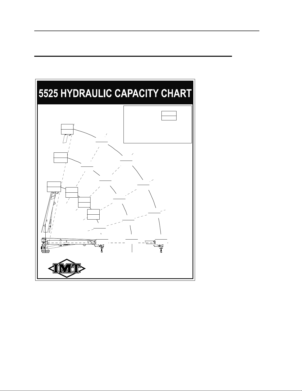
Capacity Chart, 5525
IOWA MOLD TOOLING CO., INC.
BOX 189, GARNER, IA 50438-0189
TEL: 641-923-3711 FAX: 641-923-2424 70397071
•Values in the box indicate the use of 2-
part line is required..
The weight of load-handling devices is part
ofthe load lifted and must be deducted from
the rated capacity. xxxx lb
xxxx kg
78°
60°
45°
30°
15°
0°
10500
4760 7760
3520 6290
28505515
2500
4990
2260
4460
2020
6940
3150
3635
1650
2815
1280
2400
1090
2100
950
1840
830
9500
4310 4930
2240
3870
1755
3330
1510
2960
1340
2600
1180
12'-4"
(3.75 m) 18'-10"
(5.75 m) 24'-10"
(7.57 m)
•Maximum 1-part line weight is 5500 lb
(2500 kg).
•See reduced capacity chart for
additional information when applicable.
12 Model 5525-6025-6625 Parts & Specifications Manual Part # 99904215
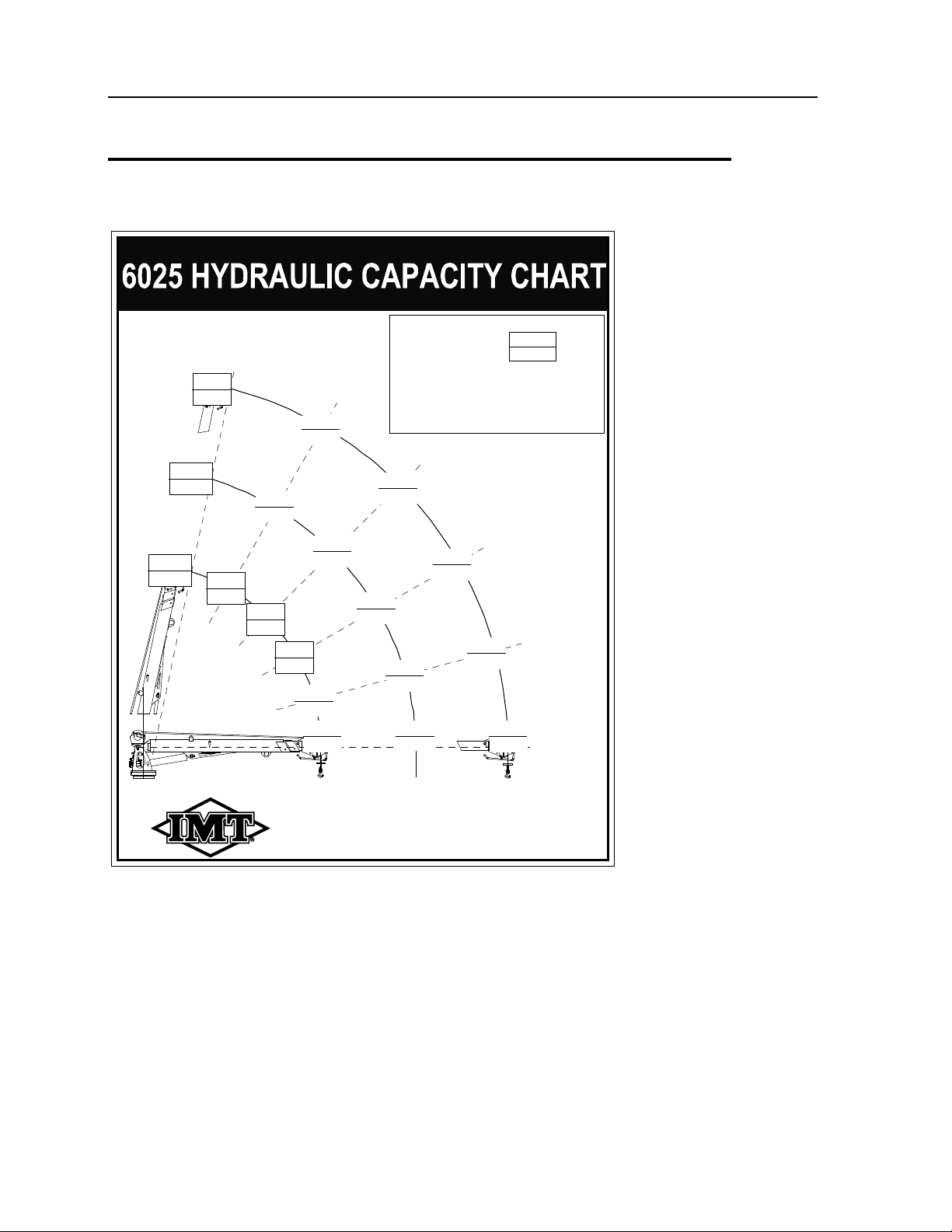
Capacity Chart, 6025
IOWA MOLD TOOLING CO., INC.
BOX 189, GARNER, IA 50438-0189
TEL: 641-923-3711 FAX: 641-923-2424
70397069
•Values in the box indicate the use of 2-
part line is required..
The weight of load-handling devices is part
ofthe load lifted and must be deducted from
the rated capacity. xxxx lb
xxxx kg
78°
60°
45°
30°
15°
0°
10500
4760 8410
3820 6720
28805540
2510
5000
2270
4870
2210
7690
3490
3980
2000
3090
1400
2650
1200
2350
1070
2070
940
10500
4760 5460
2480
4270
1940
3660
1660
3260
1480
2880
1310
12'-4"
(3.75 m) 18'-10"
(5.75 m) 24'-10"
(7.57m)
•Maximum 1-part line weight is 5500 lb
(2500 kg).
•See reduced capacity chart for
additional information when applicable.

Chapter 2 Specifications 13
Capacity Chart, 6625
IOWA MOLD TOOLING CO., INC.
BOX 189, GARNER, IA 50438-0189
TEL: 641-923-3711 FAX: 641-923-2424 70397073
•Values in the box indicate the use of 2-
part line is required..
The weight of load-handling devices is part
ofthe load lifted and must be deducted from
the rated capacity. xxxx lb
xxxx kg
78°
60°
45°
30°
15°
0°
10500
4760 9300
4220 7400
33606100
2770
5500
2495
5350
2430
7880
3575
4225
2010
3450
1570
2975
1350
2620
1190
2325
1055
10500
4760 5975
2710
4750
2155
4000
1815
3600
1630
3250
1475
12'-4"
(3.75 m) 18'-10"
(5.75 m) 24'-10"
(7.57 m)
•Maximum 1-part line weight is 5500 lb
(2500 kg).
•See reduced capacity chart for
additional information when applicable.
14 Model 5525-6025-6625 Parts & Specifications Manual Part # 99904215
Reduced Capacity Lift Charts
The Reduced Capacity Lift Chart system was conceived to inform the end user of the allowable
loads which can be lifted off the sides of a mechanics truck. IMT devised a color-coded chart
defining the sectors where less than hydraulic crane capacity can be lifted. The color-coded
chart (Reduced Capacity Lift Chart or RCLC) corresponds to a visual indicator on the base of the
crane. The RCLC displays the percentage of the hydraulic crane capacity to be lifted in each
sector. The visual indicator on the crane base gives the operator a reference of the sectors. With
this information the end user can more safely use the mechanics truck. Stability confirmation
yields data to produce a Reduced Capacity Lift Chart if necessary. Some units may not require
de-rating over the sides, but a majority will.
If the IMT crane is installed by an IMT distributor, the distributor is responsible for stability
confirmation. IMT supplies a generic RCLC decal for dealer installation.
CAUTION
CHASSIS WEIGHT, SUSPENSION, AND UNIT SET UP, INCLUDING NUMBER AND TYPE
OF STABILIZERS, LIFTING SURFACE, ETC., HAVE A SIGNIFICANT IMPACT ON
STABILITY.
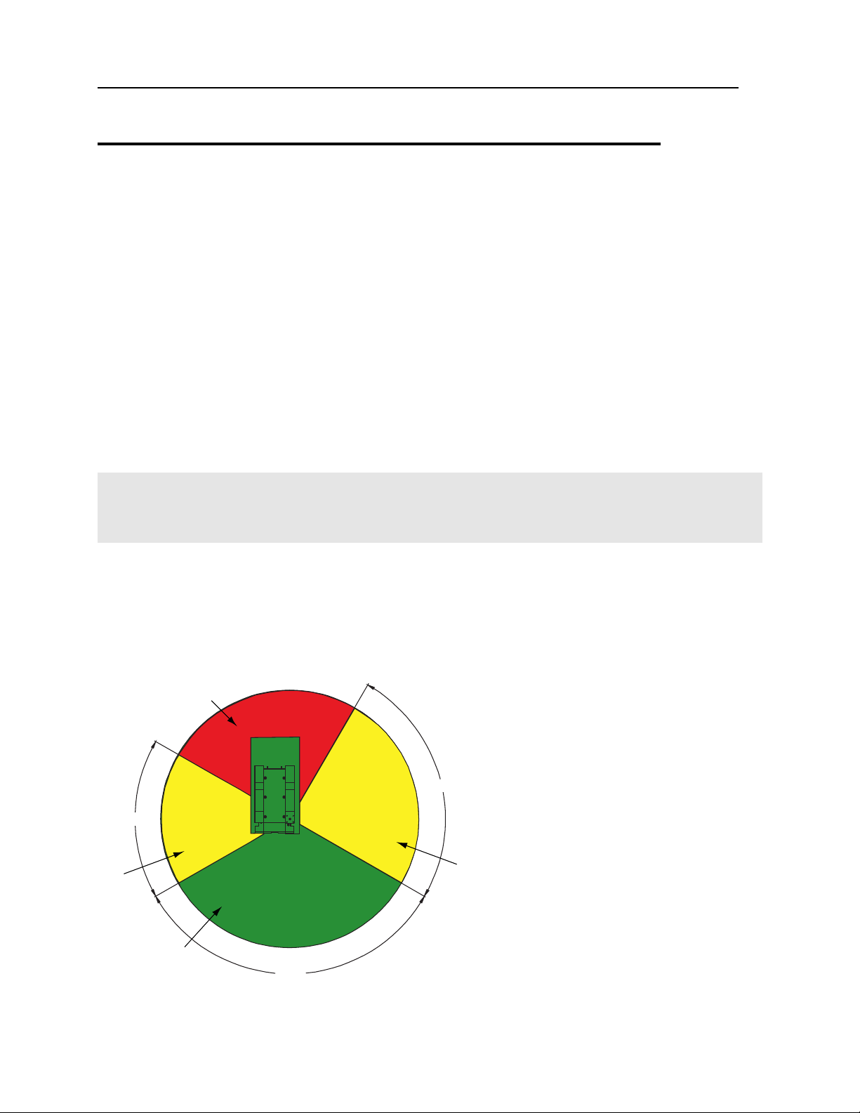
The basic illustration shows full crane capacity off the rear of the truck and reduced capacity
when lifting over the sides. Lifting over the front of the truck is not permitted.
For an IMT 5525 crane with a standard IMT Dominator® II body, the derated percentage is 80%
in the yellow quandrants. For an IMT 6025 crane with a standard Dominator II body, the derated
percentage is 70% in the yellow quadrants.
100% OF CAPACITY
CHART PERMITTED
(INCLUDES TRUCK
BED AREA)
FILL IN%
CAPACITY
CHART
PERMITTED
FILL IN%
CAPACITY
CHART
PERMITTED
LIFTING NOT
PERMITTED IN
THIS AREA
CAB
TRUCK
BED
60 °
90 °
120 °
Red Zone
Yellow
Zone
Yellow
Zone
Green Zone

Chapter 2 Specifications 15
Stability Confirmation Process
To confirm stability:
1 Set up unit on a hard, flat surface which meets SAE J765 requirements. Use all
recommended equipment such as stabilizers, etc.
2 Position the crane at full, horizontal reach. For a 5525 crane, use a 2,172 ± 10 lb test weight
suspended over the rear of the truck. For a 6025 crane, use a 2443 ± 10 lb test weight
suspended over the rear of the truck. Rotate the test weight up to the point where the pointer
on the crane base meets the yellow bands on both sides of the unit. If the unit keeps at least
one rear tire firmly touching the ground, the test can be continued for the capacity on the
sides. If the criterion is not met for the rear of the unit, a custom RCLC is required. Please
contact IMT for assistance in this situation.
NOTE
THE TIRE IS TOUCHING THE GROUND WHEN AT LEAST 90% OR MORE OF THE TREAD
SURFACE IS CONTACTING THE GROUND.
Once stability is verified over the rear section of the truck, test the stability on the sides of the
truck. Again, using the test weight in a fully extended, horizontal position, rotate the crane
around the sides of the truck. If the test weight passes the sides with at least one rear tire
firmly touching the ground, a standard Hydraulic Capacity Chart may be used rather than a
Reduced Capacity Lift Chart.
CAUTION
THE UNIT MAY TILT SEVERELY!
If the unit does not pass the side load test, you must begin retracting the booms to find the
usable percentage of the crane capacity.
For a 5525 crane, retract the booms 42” for a capacity derating to 80%. For a 6025 crane,
retract the booms 63” for a capacity derating to 70%. Measure from a fixed point on the
boom tip horizontally to a fixed point on the main boom to verify how far the booms have
been retracted. See table.
CRANE MODEL TEST WEIGHT PERCENT RATED
LOAD (%) DISTANCE BOOMS ARE
RETRACTED FROM FULL
EXTENSION (INCHES)
5525 2,172 ± 10 lb 80% 42"
6025 2,443 ± 10 lb 70% 63"
Once the booms are retracted, re-check stability by again rotating the crane around the sides
of the truck, making sure the weight passes by the yellow region marked on the crane base
with at least one rear tire firmly touching the ground.

16 Model 5525-6025-6625 Parts & Specifications Manual Part # 99904215
Test both sides of the truck. If the crane cannot rotate through the yellow zone with at least
one rear tire firmly touching the ground, you must work with IMT for a custom Reduced
Capacity Lift Chart. In this situation, please contact IMT for assistance.
CAUTION
DO NOT LIFT IN THE “NO LIFTING ZONE.”
Follow safe crane practices throughout the testing. Keep the load as close to the ground as
possible.
The minimum 90° “No Lifting Zone” over the cab must be on ALL Reduced Capacity Load
Charts. The zone may need to be increased if front stabilizers are not used. In addition, the
stability may be greater on one side of the unit than the other, but IMT has chosen to keep
both ratings the same. Thus, the lowest stability percentage is reported for each side.
Install the RCLC decal on the inside of the crane compartment door.
Keep a record of the reduced stability test to verify the decals in case replacement is
necessary.

17
In This Chapter
5525-6025-6625 Assemblies & Grease Zerk Locations............ 18
Recommended Spare Parts List...............................................19
Crane Installation ..................................................................... 20
Hydraulic Installation ................................................................21
Telescopic Crane Orientation................................................... 23
Crane Control........................................................................... 23
CHAPTER 3
Crane Reference
18 Model 5525-6025-6625 Parts & Specifications Manual Part # 99904215
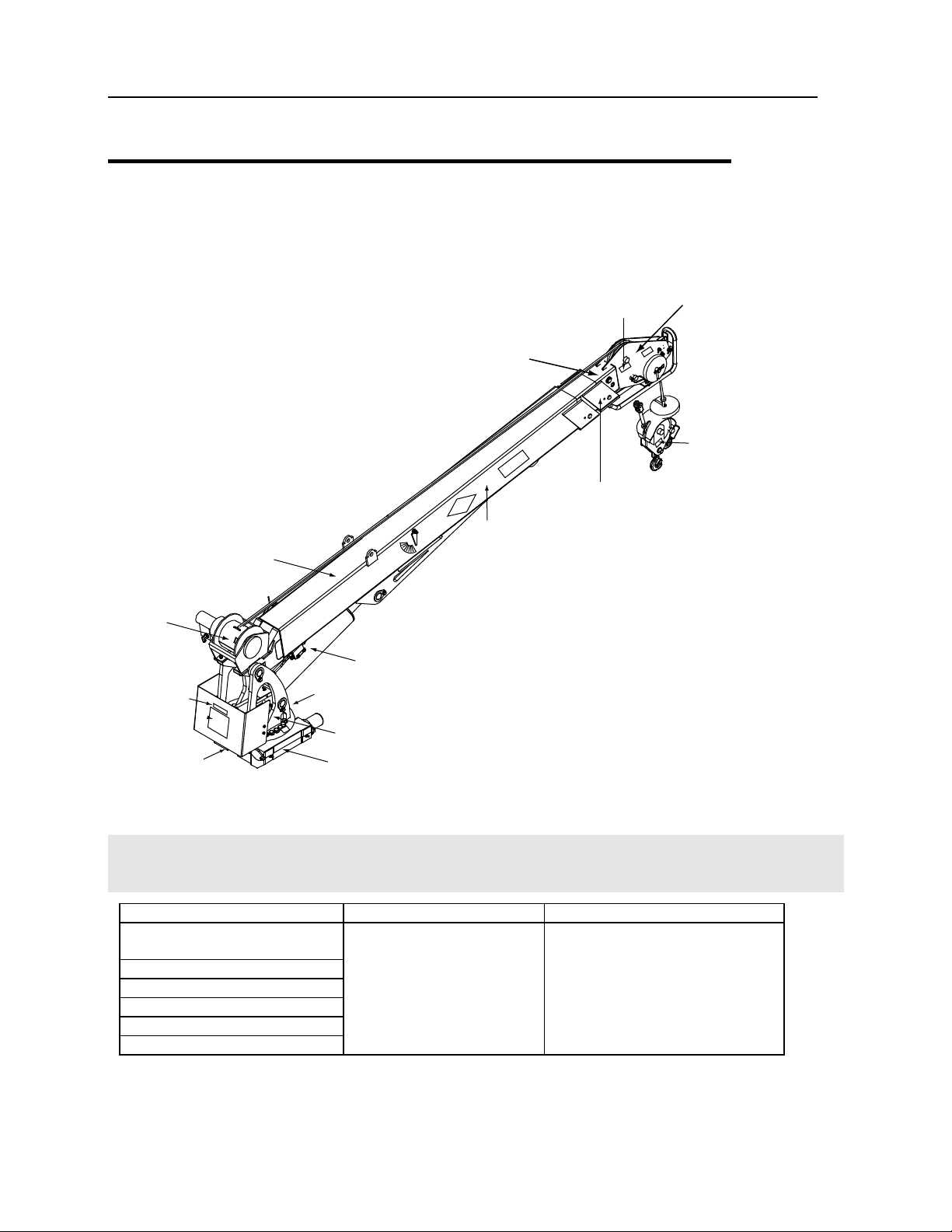
5525-6025-6625 Assemblies & Grease Zerk
Locations
Zerk
EXTENSION
CYLINDERS
(INTERNAL)
Zerk
Zerks,
both
sides
WINCH
LOWER
BOOM
LOWER
CYLINDER
1ST STAGE
EXTENSION
BOOM
2ND STAGE
EXTENSION
BOOM
BOOM
TIP
Zerk BASE
MAST
NOTE
The descriptions indicate major crane assemblies. Grease zerks are identified by the word
"Zerk."
LOCATION DESCRIPTION
LUBRICANT
FREQUENCY
Turntable/Bearing Grease
*Rotate crane while greasing
Shell Alvania 2EP or Shell
Retinax "A"
Weekly
Lower Cylinder
Lower Cylinder Rod
Upper Sheave Pin
Lower Sheave Pin
Snatch Block Pin
* Apply 3 'pumps', then rotate crane fully.
Other manuals for 5525
2
This manual suits for next models
2
Table of contents
Other IMT Construction Equipment manuals


