Faster GLOVEFAST ASEPTIC Operating instructions

0254EN –Rev. 06 –09/2019
Commercial office:
Via Merendi, 22
20010 Cornaredo (MI)
Tel. +39.02.93.991.92
Fax. +39.02.93.991.608
OPERATING AND MAINTENANCE MANUAL
GloveFAST Aseptic

a D:GROUP Company
0254EN –Rev. 06 –09/2019
Page 2 of 65
CONTENTS
1GENERAL 3
2INSTALLATION 4
2.A INSTRUCTIONS AND CHECKS ON DELIVERY 4
2.B INSTALLATION REQUIREMENTS 4
2.C ELECTRIC CONNECTIONS AND INSTALLATION OF THE WORK SURFACE 6
2.D POSITIONING OF THE ISOLATOR ON THE SUPPORTING TABLE 6
3TECHNICAL FEATURES TABLE 7
4OPERATION PRINCIPLES 8
5OPERATION 10
5.A SYSTEM AND PERFORMANCES CONTROLS 10
5.B REMOTE SIGNALS 10
5.C SYMBOLS OF THE CONTROL PANEL 11
5.D MANAGEMENT AND PROGRAMMING 14
5.E DISPOSAL OF WASTES AND CONTAMINATED MATERIALS 19
5.F MATERIALS, WHICH THE ISOLATOR IS MADE OF 20
5.G ERGONOMICS 20
6LIMITATIONS 21
7OPERATING PROCEDURES 22
7.A PRELIMINARY CHECKS 22
7.B SWITCHING ON the GLOVEFAST ASEPTIC isolator 22
7.C SWITCHING OFF THE GLOVEFAST ASEPTIC ISOLATOR 22
7.D HOW INTRODUCE MATERIAL 23
8MAINTENANCE 24
8.A INSTRUCTIONS FOR DAILY CLEANING OF ISOLATORS (by users) 24
8.B GLASS CLEANING 25
8.C REPLACEMENT OF HEPA FILTERS (by technical assistance personnel) 25
8.D REPLACEMENT OF MOTOR-FANS (by technical assistance personnel) 29
8.E REPLACEMENT OF lighting system (by technical assistance personnel) 31
9SPARE PARTS LIST 32
10 MONITORING SYSTEM 34
10.A Alarm List 35
11 TROUBLESHOOTING - Probable causes of malfunctions 36
12 TECHNICAL SPECIFICATIONS 37
13 TRANSPORT, PACKING and STORAGE INSTRUCTIONS 38
14 ADDITIONAL INFORMATION 40
14.A WARRANTY 40
14.B ADDRESS FOR TECHNICAL ASSISTANCE (for the distributor) 40
15 TESTS PERFORMED ACCORDING TO EN 14644-3 STANDARD 41
15.A MEASUREMENT OF LAMINAR AIRFLOW VELOCITY 41
15.B MEASUREMENT OF THE INTERNAL PRESSURE 42
15.C MEASUREMENT OF THE NOISE LEVEL 42
15.D MEASUREMENT OF LIGHTING 42
15.E MEASUREMENT OF VIBRATION 42
15.F CONTROL OF ALARMS 43
15.G DOP TEST FOR HEPA FILTERS 44
15.H HEPA FILTERS TESTING METHOD 45
15.I DRAWINGS AND DIAGRAMS 47
15.J DIAGRAM FOR MAINTENANCE OPERATIONS 48
16 FRONTAL DIAGRAM 49
16.A SIDE DIAGRAM 50
16.B SUPPORT TABLE Errore. Il segnalibro non è definito.
17 ASSEMBY OF THE ISOLATOR ON THE SUPPORTING STAND 51
18 SENSORS LIST 53
19 WIRING DIAGRAM 54
20 DECLARATION OF CONFORMITY 65
a D:GROUP Company
0254EN –Rev. 06 –09/2019
Page 3 of 65
1 GENERAL
Vertical laminar airflow benches with negative pressure within the working area and physical separation
between operator and product (gloves), the GLOVEFAST ASEPTIC isolators are designed to protect the
material to be manipulated from contamination coming from environment.
The dusted, filtered and sterile air passing through the main HEPA filter ensures optimum airflow laminarity
on the work surface.
GLOVEFAST ASEPTIC isolators are suitable for the treatment of high sterility sensitive materials, sterility
testing in general and wherever a high product protection is required.
The performances of the isolators are detailed in the TESTING CERTIFICATE.
Furthermore GLOVEFAST ASEPTIC isolators fulfil the harmonized standards EN 61010-1 as well as EN
61326 according to the applicable European directives regarding the CE marking.
GLOVEFAST ASEPTIC isolators comply with the above-mentioned standards ONLY if the instruments
connected to the electrical sockets inside the work chamber are "CE" marked or in any case they meet the
above mentioned standards aiming to avoid any electromagnetic interference.
All Faster’s isolators are provided with low pressure drop filters.
Faster s.r.l. cannot be held responsible for malfunctions, damage to people or property due to non-
compliance, poor or no maintenance, or improper use of the isolator.

a D:GROUP Company
0254EN –Rev. 06 –09/2019
Page 4 of 65
2 INSTALLATION
2.A INSTRUCTIONS AND CHECKS ON DELIVERY
Considering the critical nature of the use of the GLOVEFAST ASEPTIC isolator and the need to keep it in
optimum condition, installation is very important.
GLOVEFAST ASEPTIC isolator are positioned on a pallet wrapped in an extensible film and contained in a
package of multi-layer strapped cardboard or a wooden cage.
After placing the isolator in its site of use, opened the package and removed the extensible film, check that
the equipment has not suffered any dents or scratches due to transport or improper handling of the package.
In case of any further transport, packing and storage by the user after the initial period of use (e.g.: change
of laboratory or factory), contact the technical assistance service or the distributor for more accurate and
precise instructions or for assistance by specialized technicians.
GLOVEFAST ASEPTIC isolator, with or without package, should be always located in a room sheltered
from rain.
2.B INSTALLATION REQUIREMENTS
Install the isolator away from drafts and heat sources (radiators, ventilators/convectors), to ensure proper
functioning. For instance, in a small room (<30 m3), if an exhaust duct is used to expel air outside the
building, we recommend the installation of a grill in the room in order to provide an air supply equal at least
to the quantity entering in the isolator.
Install the isolator in a well-ventilated room with a low degree of dust.
The distance between the isolator and the exhaust system (if present) should be as short as possible.
Place the isolator away from doors and windows, which may cause malfunctions
Place the isolator in places where there is little human traffic.
The exhaust system should be installed on the roof or on a wall or through a window. Otherwise, it can be
connected to a chimney.
The door of the room should be in such a position relative to the isolator as to prevent drafts.
Min. temperature 5 °C
Max. temperature: 40 °C
Max. humidity: 80% at 31 °C, linear drop in relative humidity down to 50% relative humidity
at 40°C.
The exhaust duct (optional), located on top of the isolator, should be connected to the outside of the building,
alternatively it is possible the connection with the conditioning plant, but the air must not be recycled.
The maximum length of the 200mm exhaust hard duct should not exceed 10 linear meters. Otherwise
some changes must be made in the extraction fan or a remote exhaust motor-fan must be installed.
Before connecting the isolator to the mains power supply, check the necessary voltage and power indicated
on the plate near the power cable. The room must be equipped with an earth connection.

a D:GROUP Company
0254EN –Rev. 06 –09/2019
Page 5 of 65
Thimble method example
LEGENDA:
1. Exhaust air from the isolator.
2. Air from the environment.
3. Bleed Air (100
200 m3/h more than the exhaust
air flow rate from the isolator) to a dedicated
exhaust fan (in the electronic board a voltage
free contact is available –see electrical diagram-
to check when ventilation is ON).
The quantity of heat generated by the isolator, if the air is not extracted outside the room, is 240W
This heat value must be added to the heat generated by any instrument (e.g. connected to internal socket or
tap) used by the client in the work chamber.
ATTENTION: the installation must be done by technicians authorized by Faster S.r.l. or by the
official distributor.
Isolator
THIMBLE
3
2
1

a D:GROUP Company
0254EN –Rev. 06 –09/2019
Page 6 of 65
2.C ELECTRIC CONNECTIONS AND INSTALLATION OF THE WORK SURFACE
The electrical connection of the GLOVEFAST ASEPTIC isolator is made by connecting the power cable
located on the top of the right side of the isolator to a suitable power point (see technical table). When the
isolator is connected, the green light on the control panel switches on (see chapter 5).
If stipulated by local legislation, insert upstream of the power line an automatic protection overload switch
provided with a differential relay, with a rated switching voltage no greater than 30 mA.
The GLOVEFAST ASEPTIC is supplied with an electric Air Tight Valve (ATV) to close and seal the isolator
during sterilization phase or pressure decay test.
To install the work surface, proceed as follows:
- remove the protective paper from the work surface leant against the back of the isolator, taking care not
to scratch its surface,
- open the safety front window by unscrewing the four screws,
- clean the work surface with a damp cloth soaked in alcohol or soapy water or with a commonly
available product designed for stainless steel,
- place the work surface into the work chamber, let the back to slide on the chamber's supporting bases
up to its back wall,
- close the safety front window with four screws.
2.D POSITIONING OF THE ISOLATOR ON THE SUPPORTING TABLE
GLOVEFAST ASEPTIC Isolators are supplied with the relevant supporting table, which they have to be
fixed to.
After assembling the supporting table (see instructions at Para. 16) place the supporting table on a flat not
sloping floor and be sure that all the parts of the isolator, that can be opened (control board panel and sash)
are locked. Then position the isolator on the table (See instructions at Para. 17).
a D:GROUP Company
0254EN –Rev. 06 –09/2019
Page 7 of 65
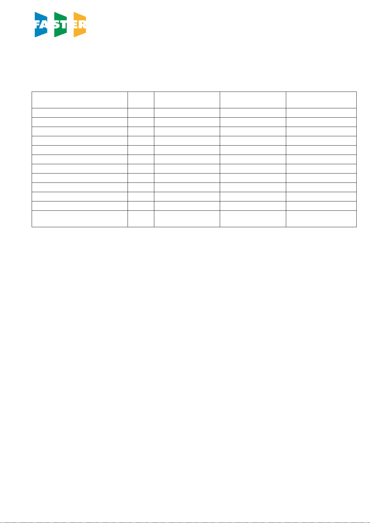
3 TECHNICAL FEATURES TABLE
Description
Unit
GLOVEFAST
ASEPTIC 2-4-2
GLOVEFAST
ASEPTIC 2-5-4
GLOVEFAST
ASEPTIC 2-6-4
Overall Dimensions (L x H x D)
mm
2510 x 2300 x 870
2815 x 2300 x 870
3120 x 2300 x 870
Useful dimensions (L x H x D)
mm
1192 x 740 x 580
1497 x 740 x 580
1802 x 740 x 580
Weight
Kg
400
450
500
Noise level
dB (A)
<55
<56
<57
Lighting level
Lux
>1000
>1000
>1000
Main voltage
V
230V AC 2P+T
230V AC 2P+T
230V AC 2P+T
Frequency
Hz
50
50
50
Power
W
2300
2300
2300
Current
A
10
10
10
Electrical class
1
1
1
Protection level
IP20
IP20
IP20
Internal outlet (maximum
current for all the sockets: 4A)
2P+T 230V 4A
2P+T 230V 4A
2P+T 230V 4A

a D:GROUP Company
0254EN –Rev. 06 –09/2019
Page 8 of 65
4 OPERATION PRINCIPLES
The following are the working principles of the GLOVEFAST ASEPTIC isolators.
The air (A) is sucked by the blower is firstly pulled through the inlet positioned on top of the cabinet and then
pushed by main blower through the H14 HEPA filter bank providing laminar flow conditions in the work
chamber and protecting the products handled. Part of the sterile air is pulled through the perforated work
surface and re-circulated behind the rear panel. The remaining part passed in the transfer hatches through
the H14 HEPA filter located the back part of the transfer hatches (providing laminar flow conditions), then
filtered by H14 HEPA filter in the upper part of the transfer hatches and finally exhausted.
D
A
A

a D:GROUP Company
0254EN –Rev. 06 –09/2019
Page 9 of 65

a D:GROUP Company
0254EN –Rev. 06 –09/2019
Page 10 of 65
5 OPERATION
5.A SYSTEM AND PERFORMANCES CONTROLS
The GLOVEFAST ASEPTIC isolator is provided with an automatic regulation system to keep the
unidirectional down flow air speed and the negative pressure in the work chamber constant even with the
progressive clogging of the HEPA filters up to the maximum pressure supported by the motor-fans.
The exhaust fan keep pressure constant at defined value, within the work chamber while the unidirectional
down flow air velocity is 0,45 m/s.
The soft-touch control panel is microprocessor-controlled with a display showing all relevant data with regard
to the operating functions, the different alarms and the error messages.
When the isolator is running if you open the front glass, this action activates an audible and visual alarm,
which cannot be silenced since there is no protection for operator.
When the isolator is off the front glass can be opened completely by unscrewing the four knobs that fasten
the glass
To optimize the visibility inside the work chamber, the isolator is ergonomically angled sloping-fronted (about
7 degrees sloping as to the vertical)
5.B REMOTE SIGNALS
On the ceiling of the isolator a PVC box contains 3 terminal clamps with the following dry contacts:
Ventilation status (ON/OFF)
It is possible to obtain a 12 Vdc output to connect a led light or alternatively a Normally Open voltage free
contact to be connected to an external circuit.
There are two different working possibilities selectable in the software:
1 The signal starts when ventilation is turned ON and stops when ventilation is OFF.
2 The signal is flashing during the start up phase of the ventilation and is ON when the correct air flow
conditions are reached.
Correct air flow conditions
It is possible to obtain a 12 Vdc output to connect a led light or alternatively a Normally Open voltage free
contact to be connected to an external circuit. That signal is closed when during safe conditions and it is
open in the following cases: door open, air flow alarm, pressure alarm.
External consent
On request with a software selection it is possible to allow ventilation to be turned ON by a remote volt free
contact. When the ventilation is turned ON the isolator stay in stand by (start up) till the remote normally
open contact is closed.
If during normal ventilation the remote contact is open the following message will appear “REMOTE
CONTACT OFF” and the operator has to switch OFF ventilation as soon as possible and then check the
reasons of the failure.

a D:GROUP Company
0254EN –Rev. 06 –09/2019
Page 11 of 65
5.C SYMBOLS OF THE CONTROL PANEL
List and description of all the symbols and controls of the touch screen control panel:
12 13 14 2 15 3 4 16
5678910 11 1
1 MAIN SWITCH:
Position "0" in the "0" position, the green light of the mains voltage is on (3); the LCD
displays the model name "GLOVEFAST ASEPTIC ". In this position the
operator can activate only the lighting system (7), the optional U.V. lamp (14)
and the power outlet (6) (with plug installed) and can see the data stored in
the microprocessor by pressing the “STATUS” key (2).
Position "I" by pressing "I" the password to enter is requested. When the password is
typed in (press arrow-up key (▲) 5 times, arrow-down key (▼) 4 times) and
SET pressed the green led of the switch lights up and the isolator starts
operating, LAF and exhaust motor-blowers are powered and first "CHECK
PANEL" then "STAND-BY" appears on the display. The LCD shows a bar-
graph indicating the ongoing start-up procedure, where the laminar flow and
the internal pressure reach the pre-set values. In addition, an audible alarm
will sound intermittently during this stand-by period, alerting the operator not
to start working yet. When the audible alarm stops and the message
"STAND-BY" disappears from the display, the isolator is ready for use. The
LAF velocity and the internal pressure are displayed.
NOTE: In any case, it is advisable to wait 5 minutes before starting to work.
2 DISPLAY Backlight liquid crystal "LCD" display composed of 2 lines of 20 characters
each showing the operating parameters and alarms.
3 LINE The green mains light switches on if the unit is connected to the mains and
the line is live.
4 WORKING CONDITION The green LED lights up when the ventilation works correctly.
5 GAS Not activated.
6 SOCKET This supplies voltage; when enabled, the display shows "POWER ON" (total
current for all sockets: 4 Amp).
7 LIGHT This switches on the lighting system; when enabled, the display shows
"Light on". Switching on the lighting system automatically the optional U.V.
lamp are switched off.
8 UP/DOWN ARROWS Use the arrow keys to scroll the menu, to program changing parameters and
to put in the password. Three passwords are programmed: 1) to start the
a D:GROUP Company
0254EN –Rev. 06 –09/2019
Page 12 of 65
isolator –2) to enter the operator menu –3) to enter the main menu to
change the data input (allowed only to authorized technical staff –service –
because unsuitable interventions can cause troubles and incorrect operation
of the isolator).
9 ESC ESC key deletes the operation of data input and goes back to the starting
condition.
10 SET SET key lets you enter the different functions or confirm the data input.
11 STATUS If pressed in sequence, the following data will appear on the display:
Internal Temperature: Shows the internal temperature of the isolator work
area; the LCD will display (for example) "INT. TEMPERATURE = 30°C”. This
value is taken by an electron probe located inside the isolator.
U.V. Lamp Residual Lifetime: Shows the operating time of the U.V. lamp
pre-set by the user with the appropriate keys. The LCD will display (for
example) "U.V. TIME=XXXX h”. When such time is over, the message "U.V.
LIFETIME OVER" will appear on the line below.
F1, F2, F3, F4 and F5 Residual lifetimes of filters: it is the operation time
of the filters installed in the isolator that can be programmed by the user.
The LCD will display (for example)" RES. TIME FILTER 1=XXXX:YY h:min".
When such time is over, the message "CHECK FILTER (es.) 1". will appear
on the line below.
The filters installed in the isolator follow the numbering listed below
TYPE of FILTERS
NUMBER
LAF HEPA
1
EXHAUST HEPA
2
INLET HEPA (top of the pass boxes)
3
OUTLET HEPA (bottom of the pass boxes)
4
LAF Power: it is shown indirectly by the power supply voltage of the main
motor, expressed as percentage of max. load voltage displayed also in
proportion by a bar.
The display shows the notice: "MOT.LAF = XX % " (max.100%).
EXH Power: it is shown indirectly by the power supply voltage of the
exhaust motor, expressed as percentage of max. load voltage displayed
also in proportion by a bar.
The display shows the notice: "MOT.EXH = XX % " (max.100%).
Operating Time: Shows the operating time of the isolator .
The LCD will display "WORK TIME = XXXXXh”. This value cannot be reset.
12 SPEED REDUCTION To place the isolator in the reduction state, a password is requested. It is the
same to start the isolator. Once confirmed, the function is enabled. When it
is enabled, LAF velocity and internal pressure are about 50% their nominal
values. The lights cannot be switched on. If they are on, they switch off
automatically. The following two messages appear alternatively:
>>>ATTENTION<<<
DANGER
And:

a D:GROUP Company
0254EN –Rev. 06 –09/2019
Page 13 of 65
REDUCED AIRFLOW
>>>DO NOT WORK<<<
The “SPEED REDUCTION” function can be enabled only when the isolator
is ON.
13 U.V. TIMER Not activated
14 U.V. Not activated
15 MUTE The red alarm LED lights up when an alarm condition occurs, which is
shown also by the message appearing on the LCD. By pushing "MUTE" the
alarm stops sounding.
16 UP/DOWN ARROWS Not activated

a D:GROUP Company
0254EN –Rev. 06 –09/2019
Page 14 of 65
5.D MANAGEMENT AND PROGRAMMING
Get access to operator menu when the isolator is in stand-by pressing “ESC” [9] together with “UP arrow” [8] keys (password). The following diagram shows the organization of the OPERATOR MENU
By pressing “SET” [10] you can either go to the highlighted entry or confirm data entry. By pressing “ESC” [9] you go back 1 menu level.
VENTILATION OFF
PASSWORD
ESC+UP
OPERATOR MENU
ALARM CLOCK SET UP
OPERATOR MENU
UV PROGRAMMING
OPERATOR MENU
UV RESID. TIME
OPERATOR MENU
LANGUAGE
OPERATOR MENU
SET UP THE CLOCK
OPERATOR MENU
CHANGE PASSWORD
OPERATOR MENU
HISTORY VIEW
ALARM CLOCK SET UP
ENABLE? YES/NO
SET ALARM CLOCK
DATE & TIME
UV LIGHTING LENGTH
DURATION: hh:mm
UV PROGRAMMING
DATE & TIME
OPERATOR MENU
FILTERS RESIDUAL TIME
UV LAMP
SET ……………….
FILTER 1 LIFETIME
SET UP ……………….
FILTER 2 LIFETIME
SET UP ……………….
FILTER 3 LIFETIME
SET UP ……………….
LANGUAGE
ITALIANO
LANGUAGE
ENGLISH
LANGUAGE
FRANCAIS
LANGUAGE
DEUTSCH
LANGUAGE
ESPANOL
SET UP THE CLOCK
DATE & TIME
CURRENT PASSWORD
……………….
SET UP PASSWORD
……………….
VERIFY PASSWORD
……………….
OPERATOR MENU
TIMER SET UP
TIMER SET UP
SET UP hh:mm
OPERATOR MENU
REMOTE CONTROL
REMOTE CONTROL
REMOTE ENABLE
ENABLE? YES/NO
OPERATOR MENU
PRESSURE TEST
START
SET
LAST TEST RESULT
START PRESSURE
FINAL PRESSURE
DURATION TEST SETUP
REPETITION NUMBER

a D:GROUP Company
0254EN –Rev. 06 –09/2019
Page 15 of 65
TIMER (countdown):
- use "UP/DOWN arrows"[8] to scroll the operator menu
- select “TIMER SET UP.” and press "SET" [10]; the display will show:
TIMER SET UP
SET UP hh:mm
- input the desired time and press SET [10] to confirm
- press “ESC” [9] to exit the operator menu
- the display will show alternatively the countdown and the standard information
- when the countdown finish an audible signal will advise the operator. It is possible silence the signal
with the “ESC” [9]
To disable the countdown:
- select “TIMER SET UP” and press "SET" [10]; the display shows:
TIMER SET UP
RESET? YES
- press "SET" [10] to confirm
- press “ESC” [9] to exit the operator menu.
ALARM CLOCK:
- use "UP/DOWN arrows" [8] to scroll the operator menu
- select “ALARM CLOCK SET UP” and press "SET" [10]; the display shows:
ALARM CLOCK SET UP
ENABLE? YES
- press “SET”[10] to confirm and the display shows:
ALARM CLOCK SET UP
DATE & TIME
- set the date and the time with the arrow keys and confirm pressing “ESC” [9]; when the time
previously set is reached and audible signal will advise the operator. Is possible silence the signal
with the “ESC” [9].
To disable this function:
- select “ALARM CLOCK SET UP” and press "SET" [10]; the display shows:
ALARM CLOCK SET UP
ENABLE? NO
- disable the alarm clock choosing “NO” and press "SET" [10] to confirm
- press “ESC” [9] to exit the operator menu.

a D:GROUP Company
0254EN –Rev. 06 –09/2019
Page 16 of 65
UV PROGRAMMING:
- use "UP/DOWN arrow" [8] to scroll the operator menu
- select “UV PROGRAMMING” press "SET" [10]; and the display shows:
UV LIGHTING LENGTH
SET UP hh:mm
- input the desired time for the UV cycle and press SET [10] to confirm
- the display shows:
.UV PROGRAMMING
DATE & TIME
- set date and time with the arrow keys and confirm pressing SET. when the time previously set is
reached the UV lamp switches ON, if the requirements to switch ON the UV lamp are not satisfied
(e.g.: glass open) an alarm message will be displayed.
- press “ESC” [9] to exit the operator menu.
UV LAMP RESIDUAL LIFETIME:
- use "UP/DOWN arrow" [8] to scroll the operator menu
- select “U.V. LAMP RESIDUAL LIFETIME.” and press "SET" [10]; the display will show:
U.V. LAMP RESIDUAL LIFETIME
set XXXX
- where XXXX shows the number of the hours set for lifetime of the U.V. lamp.
- Use the “up and down arrow” keys to adjust the hours parameter
- Then press the "SET" [10] to confirm the data and/or go back to previous menu
- To conclude programming, press ESC” [9] key.
FILTERS RESIDUAL LIFETIME:
- use "UP/DOWN arrow" [8] to scroll the operator menu
- select “FILTERS RESIDUAL LIFETIME.” and press "SET" [10]; the display will show:
FILTER 1 RESIDUAL LIFETIME
set XXXX
where XXXX shows the number of the hours set for lifetime of the FILTER 1
- Use the “up and down arrow” keys to adjust the hours parameter
- Then press the "SET" [10] to confirm the data and pass to filter 2 and so on up to filter 5
- To finish the programming, press ESC” [9].

a D:GROUP Company
0254EN –Rev. 06 –09/2019
Page 17 of 65
LANGUAGE SELECTION
- use "UP/DOWN arrow" [8] to scroll the operator menu
- select “LANGUAGE” and press "SET" [10]; the display will show:
LANGUAGE
English
- With the “UP/DOWN arrow” [8] select the desired language (Italian, English, French, German,
Spanish). Press the “SET” [10] to confirm and exit the “LANGUAGE” menu.
- Press the “SET” [10] to exit the Operator Menu and return to the standard display.
- press “ESC” [9] to go out.
SET UP THE CLOCK
- use "UP/DOWN arrow" [8] to scroll the operator menu
- select “SET UP THE CLOCK.” and press "SET" [10]; the display will show:
SET UP THE CLOCK
set XXXX
- Use the "UP/DOWN arrow" [8] to change the hours, minutes, days, month, year, weekday
- Then press the "SET" [10] to confirm the data and/or go back to previous menu
- To conclude programming, press ESC” [9].
PASSWORD CHANGE
- use "UP/DOWN arrow" [8] to scroll the operator menu
- select “CHANGE PASSWORD” and press "SET" [10]; the display will show:
CURRENT PASSWORD
PSW:
- digit the present Password then press “SET” [10]
SET UP PASSWORD
PSW:
- digit the new Password then press “SET” [10]
CHECK PASSWORD
PSW:
- digit the password again and then press “SET” [10] to confirm the data and/or go back to previous
menu
- To conclude programming, press “ESC” [9].

a D:GROUP Company
0254EN –Rev. 06 –09/2019
Page 18 of 65
DISPLAY OF HISTORICAL FILES
- use "UP/DOWN arrow" [8] to scroll the operator menu
- select “HISTORY VIEW” and press "SET" [10]; the display will show:
- use "UP/DOWN arrow" [8] to scroll through the list of the possible troubles happened. The list is in
chronological order and contains up to 64 voices.
- To conclude programming, press “ESC” [9].
REMOTE CONTROL
- use "UP/DOWN arrow" [8] to scroll the operator menu
- select “REMOTE CONTROL” and press "SET" [10]; the display will show:
REMOTE CONTROL
REMOTE ENABLE
- press again “SET” [10] and the display shows the following message:
REMOTE ENABLE
ENABLE? YES/NO
- Choose the desired option and press SET
- press “ESC” [9] to exit the operator menu.
PRESSURE TEST
The pressure test is used to find out the leakage rate of the isolator enclosure.
- use "UP/DOWN arrow" [8] to scroll the operator menu
- select “PRESSURE TEST” and press "SET" [10];
- using "UP/DOWN arrow" [8] it is possible to scroll through 3 menu:
oSTART PRESSURE TEST
oSET TEST PARAMETERS
oLAST TEST RESULTS.
a D:GROUP Company
0254EN –Rev. 06 –09/2019
Page 19 of 65
5.E DISPOSAL OF WASTES AND CONTAMINATED MATERIALS
DISPOSAL OF ELECTRIC AND ELETTRONIC DEVICES (AEE)
INFORMATION FOR EUROPEAN UNION USER
This symbol on the device means that when it needs to be disposed, it must be
handled separately from urban waste.
At the moment of the disposal, contact the dealer, to receive information about the
collect and disposal in accordance with the laws in force in the country.
Appropriate disposal of this product will help to prevent potential negative effects on health and environment
and to promote re-use and / or recycling of materials of the equipment.
The improper disposal of the product by holder involves the application of sanctions in accordance with the
regulations in their own country.
INFORMATION FOR USERS OUTSIDE THE EUROPEAN UNION
This symbol is valid only in the European Union If you want to dispose this product, contact your local
authorities or dealer and ask for the correct method of disposal.
ATTENTION: Before disposal, the isolator where contaminants and pathogens have been
manipulated, must be sterilized
The fluids of pathogenic material removed from the work surface and the liquid collection tank located under
the table as well as from the HEPA filters replaced during maintenance work are toxic and harmful and must
be submitted to special treatment. For more detailed information on such treatment, see the standards and
regulations in force on the treatment and disposal of biologically/toxic/harmful wastes.
All other materials, which the isolator is made, are recyclable but cannot be disposed as local waste
materials.

a D:GROUP Company
0254EN –Rev. 06 –09/2019
Page 20 of 65
5.F MATERIALS, WHICH THE ISOLATOR IS MADE OF
PARTS OF THE ISOLATOR
MATERIALS
External structure
Epoxy painted steel
Inside work chamber
AISI 304 stainless steel
Work surface
AISI 316L stainless steel
Motor-fans
Galvanized steel
Filters
Frame: aluminium alloy
Filtration media: glass fibre
Protection: aluminium grid/epoxy powder painted
Gasket: polyurethane
Keyboard
PE, graphite, circuits in materials compatible with Rohs regulations
Front window
Laminated safety glass
Wirings
Wires according to Rohs regulations, flame-proof cases in PVC
Cable glands
Body/nut in polyamide, inside part in EPDM
5.G ERGONOMICS
This isolator has been designed and manufactured according to the general directions on the ergonomics
provided for by the EN ISO 14738 standard.
Furthermore all maintenance operations are assured to be carried out in safety by merely following the
instructions given in this manual at chapter 8.
This manual suits for next models
3
Table of contents
Popular Industrial Equipment manuals by other brands


BIRD
BIRD TERMALINE 8201 Operation manual

Greenheck
Greenheck ESD-635D installation instructions

Zimmer
Zimmer HWR Series Installation and operating instructions

HERKULES
HERKULES AFC2 owner's manual

Endress+Hauser
Endress+Hauser CleanFit CUA 451 operating instructions

PISTER
PISTER Multicoupler PMK operating manual

SMC Networks
SMC Networks INR-244-757 Operation manual

Bosch
Bosch Rexroth UPE2 General operating instructions

morse
morse 1110 Operator's manual

Heidkamp
Heidkamp UNI-END BUFFER Instructions for assembly and operating

Antec Scientific
Antec Scientific SenCell quick start guide

Viessmann
Viessmann S3HA Series Installation, operating and service instructions