SWAN-MATIC C300 User manual

1
Need help with your Swan-Matic Capper? Call 814-474-5561 or visit www.swanmatic.com

2
Need help with your Swan-Matic Capper? Call 814-474-5561 or visit www.swanmatic.com
Contents
Set-up & Torque Adjustment ………..…………………….. 3
Maintenance & Oil Seal Replacement ……………………. 4
Clutch Adjustment ………………………………………….. 5
Swan-Matic Capper Upgrade Options ….……………….. 6
Bottles and Vial Holders ……….………………………….. 7
Insert Sizing Cart and Cap Toque Spec Guide …………. 8
Inserts and Driver Shells …………………………………. 9
Frequently Asked Questions & Troubleshooting ….……. 10
Swan-Matic Warranty …..……………………………………….. 12
3
Need help with your Swan-Matic Capper? Call 814-474-5561 or visit www.swanmatic.com
Important Note: The shell and clutch should
always stop momentarily near the end of each
stroke when contact is made with the cap.
Excessive rotation after contact will cause
premature insert wear and damage to the cap.
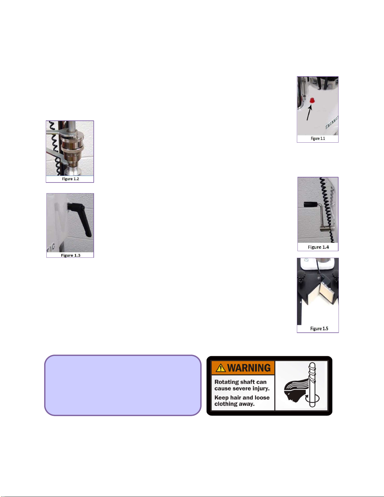
Benchtop Capper Setup & Operation
Carefully unpack the Capper and any other associated equipment which may be
in the container and check for damage. Set the machine on a level surface and
remove the red fill plug located on the top left rear of the capper head. Add the two
quarts of Gear Oil ( P/N C095 supplied ) into the housing through the fill plug hole
(Figure 1.1). The capacity is two quarts Maximum.
Attach the proper sized driver shell with a rubber insert on the
lower end of the clutch and fasten it securely with the wrenches
provided (Figure 1.2). Connect power to the electric motor after
checking to make sure that the voltage marked on the nameplate is the same as the
power supply to which the capper will be connected. Run the capper for several
minutes at room temperature to thoroughly lubricate the mechanism. The capper
should run free and easy with no effort. If it does not, inspect the capper for shipping
damage.
Accurate alignment of the container cap to the insert and proper
height and torque settings are critical for optimum capping results.
Rotate the spindle until it reaches the bottom of its stroke. Place an
already capped container under the insert, adjusting the capper
height so that the container cap just contacts the insert. The height
of the capper head is adjusted by loosening the column locking handle
(Figure 1.3) and rotating the adjustment handle (Figure 1.4). With
the capped container directly under the insert, slide the backstop
assembly (Figure 1.5) up against the container and tighten. Rotate
the spindle until you can remove the container. Readjust the capper
height directly down 1/8 to 1/4 inch (depending on the dimensions of the cap and
container) to allow for over travel. Securely tighten the column locking handle.
TORQUE ADJUSTMENT
Adjust the clutch to set the capper for the desired torque. Hold the clutch cap (the
upper section), either by hand or by using the wrench supplied, and loosen the center
lock ring several turns (Figure 1.2). To increase the torque, turn the lower clutch section
into the clutch cap. To decrease the torque, back the lower section away from the clutch
cap (Figure 3.2). When the proper torque setting has been obtained, tighten the
center lock ring (C032) to retain the setting.
4
Need help with your Swan-Matic Capper? Call 814-474-5561 or visit www.swanmatic.com
MAINTENANCE OF YOUR SWAN-MATIC CAPPER
Periodic inspection of the oil level in the capper head housing is recommended to ensure that sufficient
lubrication is present. The high oil level should be 2 3/8” from the top edge of the housing. We recommend
E.P. SAE 80/90 weight gear oil (our P/N CO95) or equivalent. Approximately once every six months, it is
recommended that the clutch be disassembled, cleaned, and a good grade of lithium grease be
applied to the clutch lining to ensure long life and consistent torque. Excessive grease may seep out
of the clutch during operation.
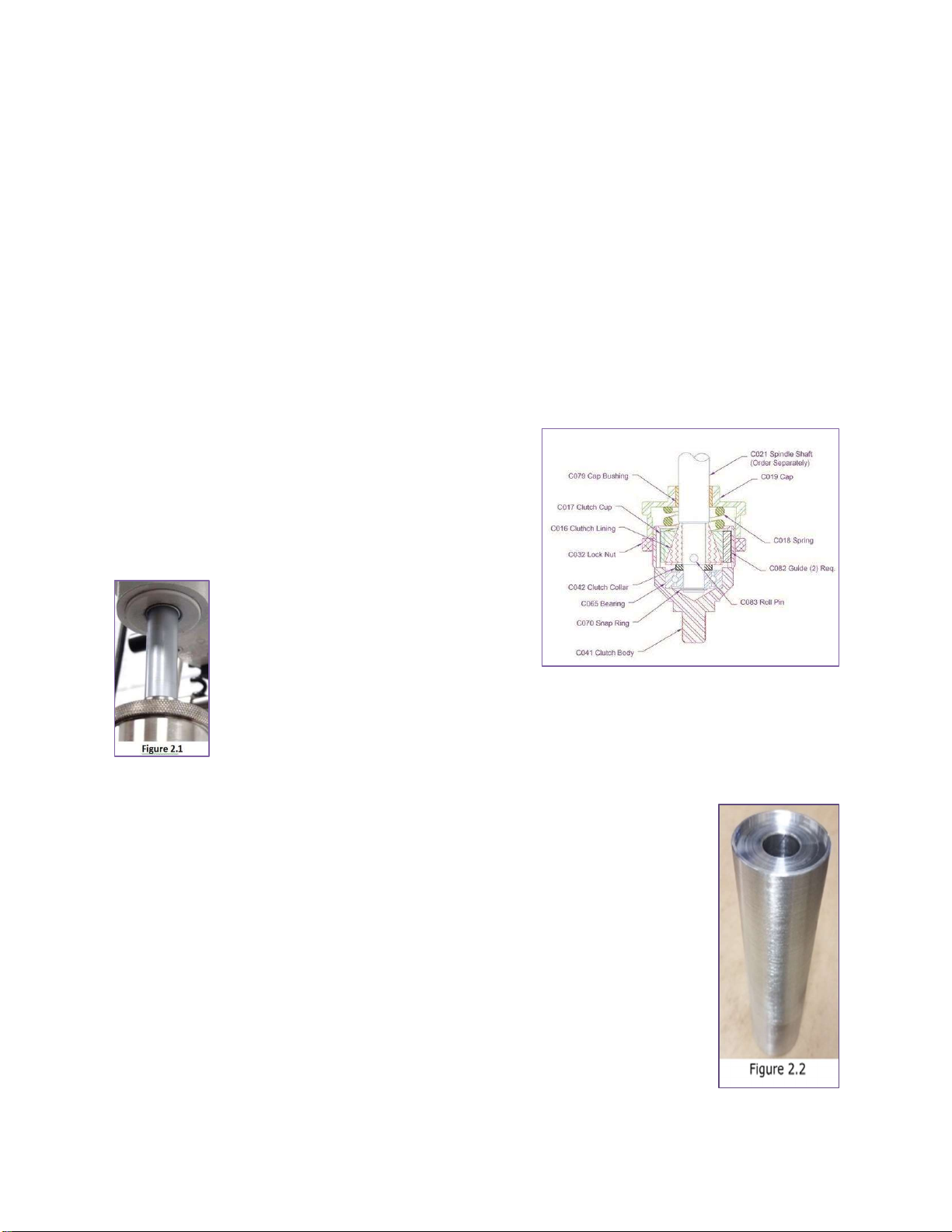
REPLACING SPINDLE OIL SEAL
Always exercise extreme caution when removing the shaft seal to
ensure the shaft itself is not permanently marked or scored.
Unscrew and remove the lower section (C041) of the clutch
from the clutch cap (C019) (upper section). This will expose
a bearing (C065) on the lower end of the spindle shaft. This
bearing is held in place with a snap ring on the underside.
Remove the snap ring and press the bearing downward to
remove the bearing from the spindle.The fiber clutch cone
(C016) is held in place with a 3/16” diameter roll pin (C083).
In removing the roll pin, be sure to use a
punch of the proper diameter. Be careful to
support the spindle shaft (C021) to
assure that it is not damaged or bent.
After the roll pin is removed, the fiber cone
and the remaining clutch parts can be removed from the spindle. The factory
recommends draining the oil before removing the seal to prevent oil loss. The shaft
seal (C059D seen in Figure 2.1) can be removed by puncturing the metal section on the
lower side of the seal and then prying the seal out of its seat. The seal can also be
removed by drilling several small holes in the metal section of the seal, inserting sheet
metal screws part way in, and then prying the seal out.
After removing the seal from its seat, thoroughly clean the seat and shaft to remove
all oil and foreign material. Inspect the shaft for score marks which could cause
premature seal failure. If any marks cannot be removed by polishing the spindle,
replacement will be required. If this is the case, contact the factory for parts and the
proper procedure at 814-474-5561.
Before installing the new shaft seal, it is recommended that the lower end of the
spindle shaft be covered with a thin coating of oil. This will allow the shaft seal to
slide along the shaft without damaging the seal. The seal should be installed with
the open side up. Before seating the seal, apply a layer of gasket sealer (i.e.,
Permatex or equivalent - our P/N C111) to the seat. Gently tap the shaft seal into
place with a hammer and a block of wood or use the optional Swan-Matic tool
C059T (Figure 2.2). Make sure that the shaft seal is not misaligned and bound in the
casting before attempting to seat it. Replace the clutch in a reverse manner from
how it was removed. Lubricate the clutch face with a good grade of bearing grease.
5
Need help with your Swan-Matic Capper? Call 814-474-5561 or visit www.swanmatic.com
SWAN-MATIC CLUTCH ADJUSTMENT TO REDUCE
DRIVER INSERT WEAR
One of the main contributing factors to insert wear is improper clutch adjustment. Each Swan-Matic capper has an adjustable
clutch above the driver shell. Proper clutch torque adjustment is essential for an insert’s proper wear time. Another
contributing factor that shortens insert life is dirt, oil or any liquids. Wipe out the insert occasionally with isopropyl alcohol and a
clean cloth. Many solvents in the products will attack the rubber insert also, causing it to swell and then break off when used
for tightening. In some cases, this can be overcome with the use of a metallic serrated driver shell instead of rubber inserts.
For a quotation, send 12 sample caps and two bottles to the Swan-Matic Division at our Fairview address.
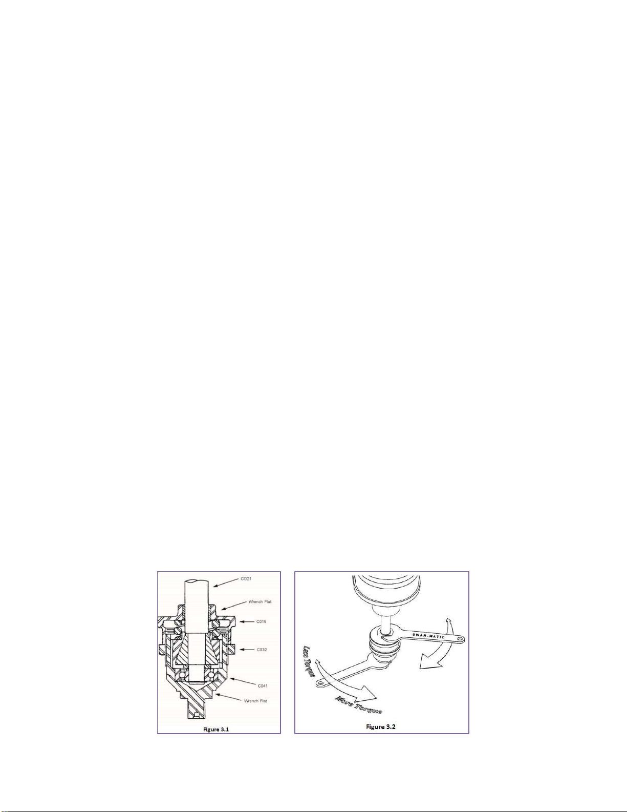
TO ADJUST THE CLUTCH:
Loosen the clutch lock nut (C032) two turns.
Standing in front of the machine with a wrench in each hand. Place your right hand wrench on the
wrench flat at the top of C019 and left right hand wrench on the wrench flats at the bottom on of
C041. Bring the two wrenches together to decrease torque and push them apart to increase
torque on your cap. (See fig. 3.2)
To increase the applied torque, tighten either wrench. To decrease the torque, loosen each wrench. (Clutch cap,
body and lock nut have right-hand threads.)
After each adjustment, hand tighten the clutch lock nut.
To adjust the height of the capping head to allow for different sized containers, stop the spindle at its lowest point
and lower the machine head until the insert touches a hand-tightened cap.
Tighten the column clamp (Page 1 Fig. 1.3) to hold the head in position.
Raise the spindle (C021) and the insert by turning on the machine, and then remove the container and cap.
Lower the machine head about 1/8 inch and retighten it.
Cycle the capper to tighten a cap onto a container. The shell and insert will stop rotating when the
cap is tight.
If the clutch does not stop rotating at the bottom of the stroke and the cap is tight, the insert will
wear rapidly. If this happens, loosen the clutch slightly. If you cannot see the shell stop, draw
vertical lines on it with a marker to help you see when the shell stops turning.
This manual suits for next models
1
Other SWAN-MATIC Industrial Equipment manuals


