FASTERHOLT FM4900H User manual

Irrigator
FM4900H
Telephone: +45 97 18 80 66
Telefax: +45 97 18 80 40
E-mail: [email protected]
Web: www.fasterholt.dk
(EN) 24-01-2022
User Manual &
Spare Parts Catalogue
Fasterholt Maskinfabrik A/S
Ejstrupvej 22
7330 Brande
Denmark

2
EU Declaration of Conformity 3
General safety 4
Operating instructions for Fasterholt FM4900H 4
Product labelling 5
Symbols used in this product 5
Operating instructions 7
Starting the FM4900H 7
Preparing the machine for irrigation 7
Preparing the machine after irrigation 8
Maintenance 8
Preparation for winter 9
Faults on the Irrigator 9
Technical data 11
Nelson SR 150 11
Spare parts 32
Front axle and drawbar 32
Front axle 34
Parts on frames 38
Guards 40
Siderne på chassis 42
Turbine for drum 46
Drum 48
Stop bracket 52
Hydraulics 54
Flat gear 58
Rear drawbar 60
Parts on rear drawbar 62
Turbine installation 64
Turbine 68
Rear axle assembly 74
Rear axle parts 80
Sensor 82
Gun 84
Contents
EEC Declaration of conformity
CVR: 58 83 28 12
TEL: +45 97 18 80 66
FAX: +45 97 18 80 40
EMail: mail@fasterholt.dk
Manufacture (name and
address):
Adresse: Ejstrupvej 22,
Fasterholt
Ort: 7330 Brande
Country: Denmark
Web: www.fasterholt.dk
Hereby is certified that the following
product:
Description, ID/mark, type:
Serial No. if any:
Notified body if any:
EEC-type certificate if any:
Harmonised standards if any:
EN 908:1999+A1:2009.
DS/EN/ISO 12100:2011.
DS/EN/ISO 14120:2015.
Is made according to the announcement no.693 of 10. Jun 2013 that implements the
DIRECTIV 2006/42/EC.
Name, title and signature of manufacture:
Date Signature
Irrigator FM 4900H

3
EEC Declaration of conformity
Fasterholt Maskinfabrik A/S
CVR:
58 83 28 12
TEL:
+45 97 18 80 66
FAX:
+45 97 18 80 40
E‑Mail:
mail@fasterholt.dk
Manufacture (name and
address):
Adresse: Ejstrupvej 22,
Fasterholt
Ort: 7330 Brande
Country: Denmark
Web: www.fasterholt.dk
Hereby is certified that the following
product:
Description, ID/mark, type:
Serial No. if any:
Notified body if any:
EEC-type certificate if any:
Harmonised standards if any:
EN 908:1999+A1:2009.
DS/EN/ISO 12100:2011.
DS/EN/ISO 14120:2015.
Is made according to the announcement no.693 of 10. Jun 2013 that implements the
DIRECTIV 2006/42/EC.
Name, title and signature of manufacture:
Date Signature
Irrigator FM 4900H
EU Declaration of Conformity

4
!!! Important!!!
READ THIS MANUAL BEFORE USING YOUR IRRIGATOR!!
Operating instructions for Fasterholt FM4900H
Your new Fasterholt Irrigator is a Danish built machine, but even the best
machines only deliver top results when they are properly used and maintained.
To ensure that the machine complies with the EU Machinery Directive, it is
important to use the original machine parts. If non-original parts are used,
compliance will not be maintained and you will be responsible for your own
safety.
The irrigator is intended for irrigation with clean water from a drilled well or a
watercourse.
Safety instructions/warnings!!
―It is forbidden to stand on the machine during irrigation and transport
(risk of fatal injury).
―The guards are tted for your own safety - please leave them in place.
―Remember to tighten the wheel bolts.
―When starting the machine on falling ground, you must be VERY careful
not to disconnect the tractor from the machine until the machine has
been put into gear, otherwise the machine may run away.
―If a rear wheel is removed, THE MACHINE MUST BE JACKED UP AND
VERY STABLE, because if it overturns, it will fall completely on its side.
WARNING!!
―To perform an EMERGENCY STOP, pull the cable for the miswinding bar
or press STOP on the COMPUTER.
―The gun must face out to the side when unwinding the machine.
―STAND ASIDEwhen the gun is operating.
―WARNING against contact with overhead power lines with the machine
or water jet. Avoid irrigation on or near power lines.
―During transport on uneven roads/elds, move VERY carefully according
to the conditions.
―Max. transport speed with water in the hose is 15km/h.
―When parking the machine, use the wheel chocks mounted by the rear
wheels.
―DANGER!! Avoid welding in the paint layer! Before welding, remove all
paint from the welding area.
―Avoid inhalation of grinding dust.
―Hydraulic oil can be harmful to health:
―Skin contact may cause allergies.
―Inhalation of oil mist may cause lung disease.
―Leakage of oil under high pressure is dangerous, an oil jet can enter the
skin, eyes, etc.
―If a hydraulic system leak is found, stop the system immediately and
rectify the fault.
―Note that due to operation, the oil may be 70degrees Celsius or even
hotter. This can lead to a risk of scalding during separation.
―IMPORTANT.Maximum battery charging power is 2 amps. Charging
more than 2 amps may cause the battery to crack. The battery must be
charged at a temperature between 0 °C and +40 °C. Avoid sparks and
ames on and around the battery.
―Do not short circuit the battery.
―Never disassemble the battery.
―If you come into contact with the battery's sulphuric acid, wash
immediately with water. If acid comes into contact with eyes, rinse
thoroughly with water and seek medical attention immediately.
―Pay attention to the battery compartment. If there are cracks,
deformities, electrolyte leakage, etc., replace the battery immediately.
―If the battery is dirty, clean it as soon as possible.
―Disposal of oil spills:
―If oil spills are found, they should be cleaned up immediately with rags
or oil absorbent powder.
―Spilled products, as well as rags and powder used for oil spills, must
be stored in sealed metal containers and delivered to the municipal
collection site.
―Batteries, hoses, tyres and other parts of the irrigation machine must be
disposed of at an approved recycling site.
If the machine is to be moved via public roads, it must rst be drained of
water.
General safety
5
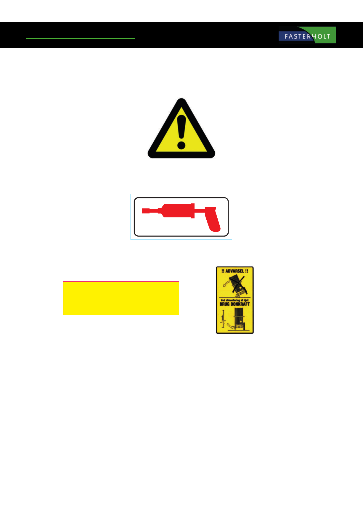
Product labelling
Symbols used in this product
The following symbols are used in this product and the following documentation.
WARNING Indicates a potentially dangerous situation which, if not prevented, could
result in death or serious injury.
LUBRICATION Indicates lubrication is required as per the service description
SERVICE WARNING Indicates a service hazard
SMØRING
HUSK efterspænding
af hjulbolte

6

7
Operating instructions
Starting the FM4900H
Move the machine to the eld in the transport position. When the machine
is at the crop to be irrigated, disconnect the tractor from the front drawbar.
Connect the tractor to the rear drawbar. Insert the electric brake connector
in the female connector for the tractor lights. The machine then winds up in
the crop and stops.
Disengage the stop pawl at the hose drum.
The stop pawl at the hose reel is disengaged when laying the hose.
Remember!! When starting the machine on falling ground, you must be
VERY careful not to disconnect the tractor from the machine until the
machine has been put into gear, otherwise the machine may run away.
Safety stop
During irrigation
During transport
Secure the long ground spikes. Lower the drawbar over the hose , and
release the safety stop so the hose reel runs on the hose.
The machine should be unwound completely at least every 3rd time.
Before starting to unwind the machine, reset PROGRAM RAIN. To do this,
press the TOGGLE SWITCH located on the side of the electric box upwards
(reset).
When unwinding the machine, the TOGGLE SWITCH must be in the centre
(unwind) so it cannot reset on the way out. After unwinding, press the
TOGGLE SWITCH down (operation).
ALWAYS REMEMBER that the TOGGLE SWITCH must be pressed down
during operation, otherwise the machine will not move.
Unwind the machine at max. 5 km/h to keep the hose tight on the drum at
all times with the electric brake. If you do not lay the hose straight out be
very careful to ensure that the hose is always tightened on the hose drum.
Preparing the machine for irrigation
Disengage the stop pawl at the hose to enable operation.
Also remember to release the electric brake and disconnect the electric
brake connector from the tractor.
Ground spike
8
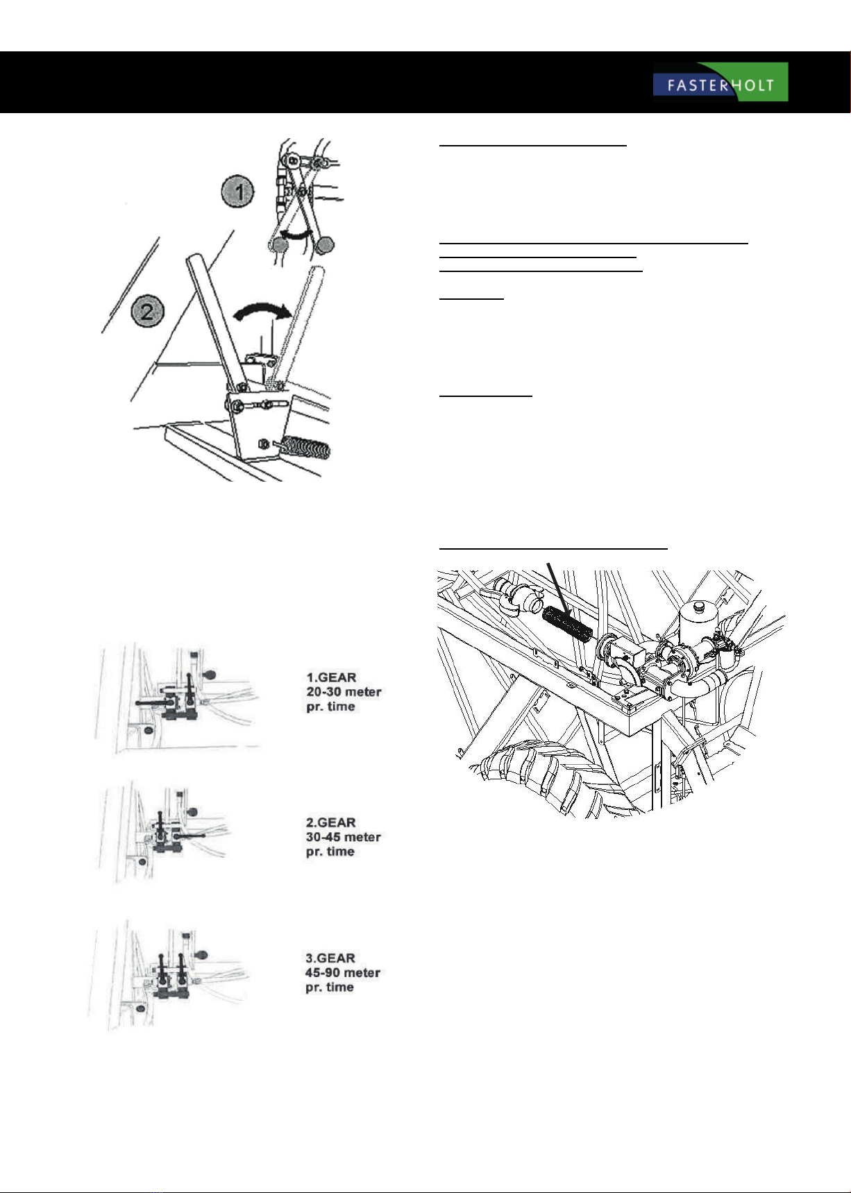
Remember to close the decoupling valve (Lever "1" must be pulled out)
and to engage with the coupling lever.
(Lever "2" pulled out)
Attach the charge hose to the hydrant. Then open the hydrant, start the
pump and irrigation can begin.
When starting irrigation, see the operating instructions for PROGRAM RAIN.
Put the machine in gear. (Remember to select the right gear for the speed
you want to drive at.) (Refer to table below or on the machine for electrical
control.)
Preparing the machine after irrigation
After each irrigation, open the bypass valve (Lever "1" must be pushed in)
to get the gearbox out of gear (Lever "2" pulled out).If there is tension in
the rear axle assembly, use a fork wrench to turn the input shaft to release
the coupling.
ALWAYS REMEMBER THAT THE COUPLING MUST BE RELEASED
(COUPLING LEVER PULLED BACK) WHEN
THE MACHINE IS NOT MOVING BY ITSELF.
Maintenance
1x per week:
Check that no water is entering the oil on the rear axle assembly and
hydraulic system.
Lubricate the steering, roller chain for hose guides, roller chain for forward
traction, cross track shaft for hose guide with water-repellent grease.
Check tyre pressure:
Rear wheel air pressure: FM4900H: 2.3 bar
Front wheel air pressure: FM4900H: 4.7 bar
Check that front and rear drawbars line up.
Clean the lter at the turbine outlet if required
Check that the hose is positioned neatly on the hose drum.
Remember to check the guide pins in the hose guides regularly.
Remember to tighten the wheel bolts regularly.
Tighten rear wheel bolts to: 450 Nm
Tighten front wheel bolts to: 330 Nm

9
NOTE:
The battery should be charged once a month during the season to maintain
full power and extend its useful life.
Preparation for winter
Drain water from the machine:
Water can only be drained from the machine with air.
Use the special compressor for draining.
REMEMBER!!
Open the lter coupling.
Open the valve in the base of the turbine
On machines with high pressure stops START to open the main valve and
allow the water to ow out freely. (Disconnect battery lead so stop valve
does not close again.)
Remove the battery and do not install it until the next time you use the
machine.
Lubrication of:
Front wheel hubs, front spindle, hose guides, bearings on hose guides,
wheels.
Check for water in the oil in the rear axle assembly and hydraulic tank. Oil
in the rear axle assembly / at gear should be changed every 1,000 hours.
Hydraulic oil and lter should also be replaced every two years.
Lubricate the steering, roller chain for hose guides, roller chain for forward
traction, cross track shaft for hose guide with water-repellent grease.
Check tyre pressure:
Guide pins should be replaced every year.
Check the following before calling a technician:
1. If the machine is irrigating, but not moving:
a. Check that machine is in gear.
b. Check if it is performing pre-irrigation or post-irrigation. (can be
seen on the display under menu 3.)
c. Check if pressure drop valve is closed.
d. Check that end stop sensor is in place.
(Can be seen on the display under menu 2.)
Faults on the Irrigator
e. Check that toggle switch is in operation position.
f. Check that decoupling valve is closed (for hydraulic motor).
g. Check that lter at turbine outlet is not blocked.
h. Check that turbine can turn easily.
2. If the machine does not wind up the hose properly, it may be
that:
a. The hose guide needs to be adjusted:
To adjust the guide, remove the chain from the hose guide to
the cross track shaft. Then turn the cross track shaft until the
hose guide ts the hose again. Then t the chain.
b. The guide pin is worn and needs to be replaced.
c. There is not enough pressure on the drum winder. (call a
technician).
3. Front and rear forced steering are not aligned and forced steering
is sprung on impact:
a. There is a leak at the coupling or assemblies, so the oil has
drained out, leaving air in the system.
b. The system must be vented. (call a technician).
Data for FM4900H with dual pump
Hose PEL 110 mm:
Capacity up to 70m3- hose length from 675 to 800 m.
Hose PEL 125 mm:
Capacity up to 100m3- hose length from 500 to 650 m.
Wheel size:
Rear wheels: 16.9"/14 x 30" x 8 ply: 1.7 bar
Front wheels: 400"/60 x 15,5" x 14 ply: 4.7 bar
Speed at 55 m3 and above:
20 - 45 m per hour
Weight of FM4900H:
Weight without water with 800 m/110 mm hose: 6000 kg.
Weight with water with 800 m/110 mm hose: 11800 kg.
Track width: 2010 mm
Gun: Nelson SR 150
Oil and lubrication:
Oil in rear axle assembly: 25 litres 80/90 gear oil
Oil in at gear: 1.5 litres 80/90 gear oil
Oil in oil motor gear: 3.5 litres 80/90 gear oil
(every 2 years)
Hydraulic oil (Tank): 14 litres STATOIL
Hydraway HVXA 46
Grease for lubrication: STATOIL Moly Way
EP2 or equivalent.
Width: 245 cm
Length without drawbar: 630 cm
Length with drawbar: 915 cm
Height: 419 cm
Optional equipment:
Electric brake set with brake block.

10
11
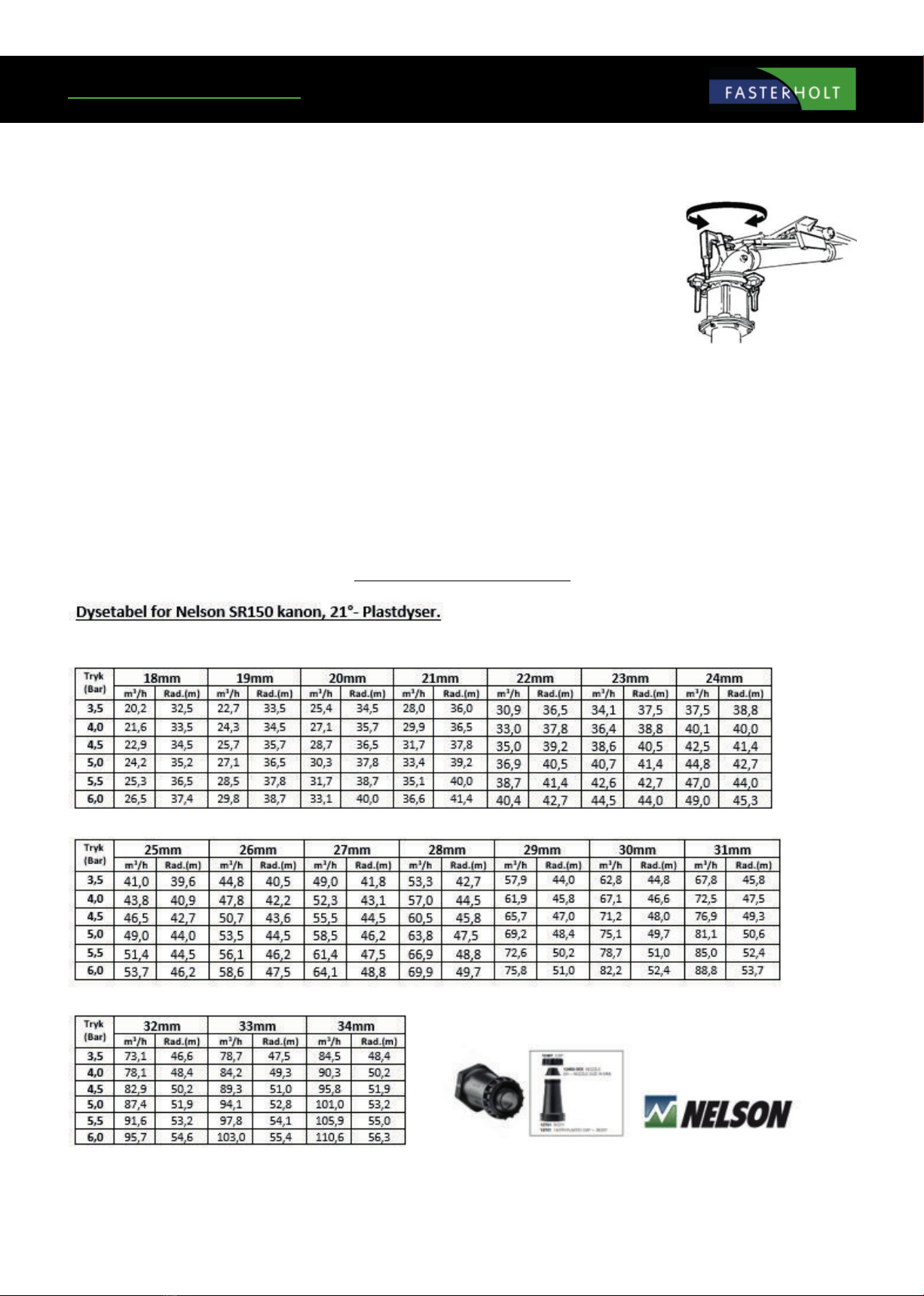
Nelson SR 150 is factory-adjusted to Danish conditions and ready to use after the following three steps:
1. Select and install the nozzle size that best suits your application. Performance data for the dierent sizes are shown in the table below.
2. Adjust the stop on the part circle to obtain the desired irrigation angle.
There is a grease nipples which should be checked once a week for relling.
ADJUSTMENT
The only thing you can adjust is the counterweight on the drive arm.
By moving the counterweight forward, the gun will slowly irrigate from side to side. If you move the counterweight
back, the gun will irrigate quickly. If it does not irrigate quickly enough, you can remove the brake springs (no.
778474) in pairs (contact the service department).
WARNING: DO NOT ADJUST WHEN THE GUN IS IRRIGATING!!
DANGER........: HIGH WATER PRESSURE – STAY CLEAR!!
TABLE FOR NELSON SR 150
Technical data

12
Functions:
Speed regulator
Pre- and Post-irrigation
4 dierent speeds on sections of the lane
Clock
Setting the start time
Stop time is shown on the display
Length of hose
Current speed
Battery volts
Charge regulator
Pressure sensor
Stop sensor
Speed sensor
Motor 1, regulating motor
Motor 2, stop motor
Slow start of turbine
Slow closing of inlet
Water volume + spreading width
Accessories:
GSM, SMS messages for remote control.
Analogue pressure sensor.
13
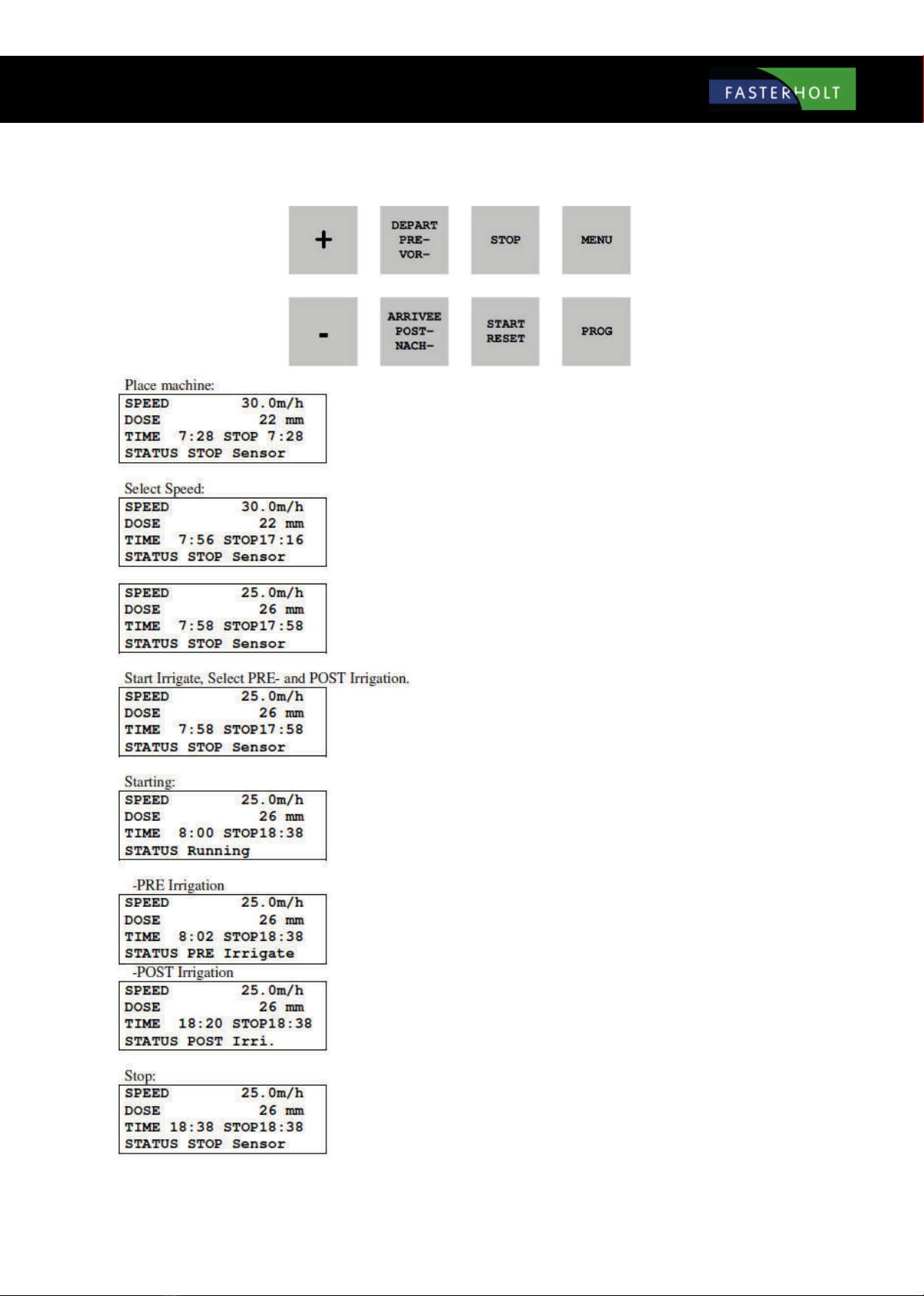
Short instructions for use
Move machine to a new lane. Display shows start and stop time. Pull hose out to end
of the lane. (e.g. 250 m)
Display now shows stop after 9h 20m. Press the "+" or "-" key to set the speed. Speed
can be adjusted during irrigation.
SPEED has decreased, DOSE has increased and STOP time is later.
Press START to start. Press PRE and POST for pre- and post-irrigation respectively.
STOP time will be later when PRE and POST irrigation are selected.
The turbine will start when the water pressure increases. After a short period, the
regulator nds the correct speed. Irrigation continues until STOP SENSOR is activated
at the end of the lane.
If pre-irrigation is selected, the turbine stops immediately after performing a start and
pre-irrigation. When the pre-irrigation time has elapsed, the turbine starts and the
machine changes status to Irrigating.
If post-irrigation is selected, the turbine stops at the end of the lane when the stop
sensor is activated. Post-irrigation then starts.
Stop sensor is activated, turbine and water are shut o. The machine is now ready to
be moved to a new lane.
14
General instructions for use
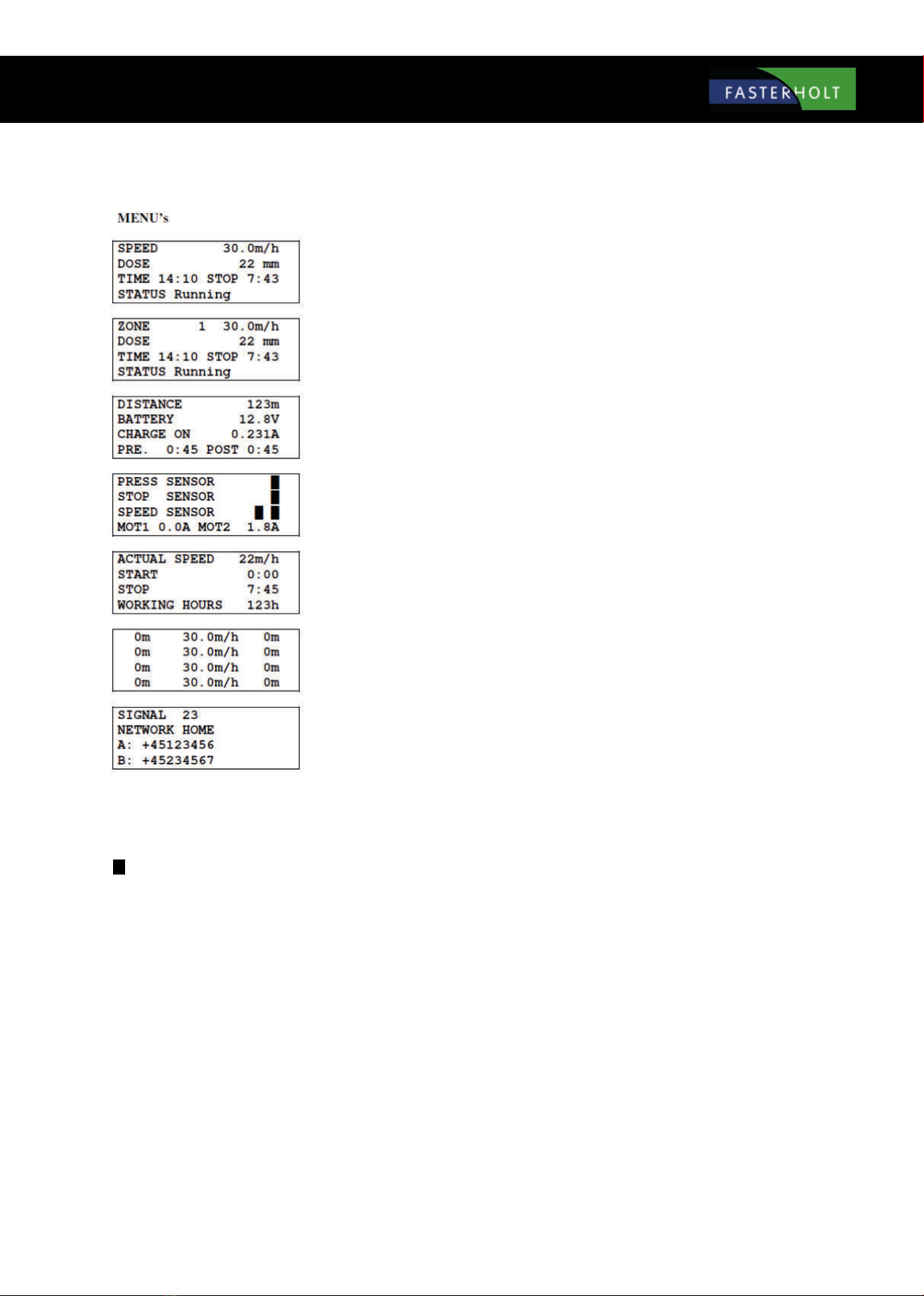
Standard display
Standard display, ZONE irrigation is selected.
Press the MENU key 1 time to display menu 2
Press the MENU key 2 times to display menu 3
Press the MENU key 3 times to display menu 4
Press the MENU key 4 times to display menu 5
Press the MENU key 5 times to display menu 6
(Only if GSM is selected)
When appears in the display, this indicates that the relevant function is ON.

15
Standard menu:
Standard display
SPEED
ZONE
DOSE
TIME
STOP
STATUS
Speed. Can be changed at any time during irrigation using the "+" and "-" keys.
Current zone 1...4, with corresponding speed. The speed cannot be changed. (Zone active)
The dose is calculated from the speed and constants and shows the current number of mm for irrigation. As SPEED increases,
DOSE decreases. (Constants 11 and 12)
To set the time: Set SPEED to 11.1 m/h and press the PROG key 3 + 1 times until the display shows <CONST 1 TIME>. The
time can then be set with the "+" and "-" keys. When the battery has been disconnected, the clock will show 0:00 until it is set
again.
The time that irrigation is completed, incl. pre- and post-irrigation. If the clock is not set and shows 0:00, the total irrigation
time is displayed.
Irrigation status, e.g.:
<Stop sensor >
<Irrigating >
<Pre-irrigating >
<Post-irrigating >
<LOW pressure >
See explanation in STATUS chapter.
If the display shows: LOW BATTERY instead of SPEED, the battery voltage is below 11.8 V and the battery needs to be charged.
DISTANCE
BATTERY
CHARGER ON
PRE
POST
Length of the unwound hose. The length can be changed immediately after pressing the PROG key 3 times, using the "+" and
"-" keys.
Battery voltage.
Shows when the battery is being charged by a solar cell. The battery is charged when the voltage is below 14.0 volts.
Shows the pre-irrigation time.
Shows the post-irrigation time.
The pre- and post-irrigation times can be changed immediately after pressing the PRE- or POST- keys, using the
"+" and "-" keys.
MENU 2

16
MENU 3
PRESSURE SENSOR
Shows that the pressure is high when block is lit. The machine can only move when the pressure is high. If no pressure sensor is
tted (machine data 14 = 0), the machine will operate regardless of pressure status.
The machine can be tted with analogue pressure sensors. Sensors must be connected according to the diagram. Pressure sensor functions,
except for pressure display, are the same as for digital pressure sensors. There are constants for the pressure sensor type. Similarly, set point
and hysteresis can be selected for each machine.
Shows pressure in [BAR] (00.0) or [PSI] (000). Pressure is high when is lit.
The machine can only move when the pressure is high.
If no pressure sensor is tted (machine data 14 = 0), the machine will operate regardless of pressure status.
STOP SENSOR
Shows that the magnet is aligned with the stop sensor when block is lit.
The machine can only start when the magnet is aligned with the stop sensor.
The stop sensor has 3 functions:
1. Reset distance.
2. Post-irrigation.
3. Stop pulses to the regulator motor.
SPEED SENSOR
For the speed sensor test, block is only lit when the magnet passes the sensor.
MOT1, MOT2
Displays the current motor current. When the current exceeds 4.5 A, the motor stops.
If the current exceeds 4.5 A and the valve is not in the outer position, there may be a blockage in the valve.

17
MENU 4
CURR. SPEED
START
STOP
OPERATING HOURS
Shows the current speed. That is, the speed at which the machine is moving now. This can be used to nd how fast the
machine can move. The current speed may dier slightly from the set speed, especially at the start. This does not matter, as
regulation ensures that the average speed within 10 metres is correct.
Start machine delay. The machine start time can be delayed by up to 24 hours. To set the start time, press the PROG key 3
times, then set the time using the "+" and "-" keys.
The time that irrigation is completed with a delayed start.
Shows how many hours the machine has been running since the electronics started for the rst time.
MENU 5
This menu is for irrigation at dierent speeds in zones of the lane.
Press the PROG key 3 times to program the zones.
See later chapter for details.

18
MENU 6
SIGNAL GSM signal strength.
NETWORK GSM network.
A: First number on "SMS" list.
B: Second number on "SMS" list.
See GSM chapter for details.
START:
The turbine can only start if the magnet is aligned with the end stop sensor (or end stop sensors). See menu 3 for control of the STOP SENSOR. Press the
START key to turn on the water. The regulator valve for bypass around the turbine then closes. (Turbine starts). If the end stop sensor is not in place, only the
main valve can be opened, which then immediately closes again. Used to relieve pressure before removing charge hose from hydrant.
DEFERRAL OF START TIME
First press the STOP key to shut o the water supply. Then press the MENU key 3 times and PROG 3 times. The start time can be set using the "+" and "-" keys.
Finally, select pre- and post-irrigation. To exit, press MENU.Info: The clock can only be set forwards.
STOP:
When the magnet is removed from the end stop sensor, the turbine stops and the main valve shuts o the water (turns on the water at negative pressure). If
post-irrigation is selected, rewinding stops when the magnet is removed from the sensor. When the post-irrigation time has elapsed, the main valve closes.
When the STOP key is pressed, the turbine stops immediately and the main valve shuts o the water, regardless of whether post-irrigation is selected.
SUPERVISION:
Program Rain has a built-in supervision system. The supervision system will be activated if for any reason the machine has water in the same location for
longer than a specied time. This time is factory-set to 20 minutes. If the time is set to 0, there is no supervision. (See constants on page 17 for setting the
supervision time.) If speed supervision less than 50 % of pre-selection is required, select speed supervision together with the above time.
SPEED:
The speed is set using the "+" and "-" keys. First count up in steps of 0.1 m/h. After 10 steps, count up in steps of 1 m/h. The speed can be changed at any
time during irrigation. If the speed changes during irrigation, the dose and time for the remaining irrigation will be calculated immediately based on the new
speed.

19
PRE-IRRIGATION:
If pre-irrigation is required, press the PRE- key. The pre-irrigation time is calculated as 8 x the time to move 1 m at the current speed. The constant can be
changed individually for pre- and post-irrigation. (See constants). If pre-irrigation is selected, the machine will move forward approx. ½ m, after which the
machine will stop and stand still for as long as pre-irrigation is performed. Menu 2 shows the number of minutes remaining of the pre-irrigation time. If you
want to cancel pre-irrigation, press the START key. This will cancel both pre- and post-irrigation and the turbine will start.
POST-IRRIGATION:
If post-irrigation is required, press the POST- key. The post-irrigation time is calculated as 8 x the time to move 1 m at the current speed. The constant "8" can
be changed individually for pre- and post-irrigation. (See constants on page 17). Post-irrigation starts counting down when the magnet is removed from the
stop sensor. When the stop sensor is activated, the turbine stops and post-irrigation starts counting down (see menu 2). When the post-irrigation time has
elapsed, the main valve closes. (Opens in installations with negative pressure stops). For machines with mechanical end stops: The turbine stops when the
stop sensor is activated. When the post-irrigation time has elapsed, the turbine starts and the machine moves to the mechanical end stop. Press START to
cancel post-irrigation. If constant "8" (early stop) is selected, the machine will stop when it reaches the selected distance.
PROGRAMMING 4 DIFFERENT SPEEDS:
The hose must be unwound before programming, so the computer knows the number of metres in the irrigation lane. The following example assumes that
the unwound hose is 400 m. Press the PROG key 3 times and the display will show:
The desired speed can now be selected, in this case 25.0 m/h. Press the PROG key and the display will show:
The desired distance can now be selected, in this case 300 m. Press the PROG key and the display will show:
Now that the rst zone is programmed, apply the same procedure to all 4 zones. Zone 4 automatically ends at 0. When zone 4 is programmed, press the
PROG key again and the display will show:
If PROG is pressed, the program is stored and irrigation will be performed according to this program.
If MENU is pressed, the program is deleted and the speed is the same for the entire irrigation lane.

20
STATUS Status line in display
**IRRIGATING** The machine has not started, but speed signals are being received and it is attempting to maintain
the selected speed.
IRRIGATING: The machine is irrigating and functions as intended.
LOW PRESSURE: Water pressure is low. Individual action according to constants and machine data.
STARTING: User has pressed the START key and start sequence is being performed.
START TELE: The machine is starting after receiving an SMS.
START TIMER: The machine is waiting for start delay. (See Menu 4).
START PRESS: The machine is performing a start after pressure rise. The machine uses the pressure level to start a
second machine on the ground line.
START REJECTED: User is pressing the STOP key to block PRESSURE and SMS start.
STOP USER: User has pressed STOP and the machine has stopped.
STOP TELE: The machine has received an SMS with STOP and has stopped.
STOP SENSOR: The machine has reached the end and is stopped by STOP SENSOR.
STOP DIST: The machine has reached the stopping distance. (See constant for early stop)
STOP DELAY: The machine has reached the end, but waiting xx seconds to perform the stop sequence.
STOP REJECTED: User is pressing the START key to block SMS stop.
STOP MONITOR: Monitoring has stopped the machine. The machine has not moved for xx minutes. (See constant for
monitoring).
CREATE PRESSURE DROP: The machine is creating a pressure drop to stop the main pump. After 2 minutes, the valve closes to
prevent draining the ground line.
PRE-IRRIGATING: The machine is performing pre-irrigation.
POST-IRRIGATING: The machine is performing post-irrigation.
This manual suits for next models
1
Table of contents
Popular Personal Care Product manuals by other brands


HARD
HARD Stockton N1035P Instructions for the assembly

Mangar International
Mangar International Freedom Airflo Mk3 User instructions and warranty

Geberit
Geberit Option Plus quick guide

medi
medi protect.Knee immobilizer Instructions for use

Bort
Bort OmoXpress Instructions for use

Nasco Healthcare
Nasco Healthcare heartisense BABY+ BUDDY user guide


