Fastnet Radio FMD15 User manual

OPERATOR
MANUAL
GMDSS Marine Radio
Decoder
FMD15
FMD
September 1999 V 1.xx

September 1999 V 1.xx
ATTENTION
IMPORTANT INFORMATION
The FMD15 has two M5 threaded holes on either side
for the supplied thumb screws, so that it can be fitted
to the universal mounting bracket. The length of the
thumb screws has been so determined, that, together
with the bracket and the lock washers, they can only
penetrate approx. 5mm into the thread.
Should you use alternative fitting methods or screws,
please make sure that they do not penetrate the
thread by more than 5mm.
By using longer screws, the integrated electronic could
be damaged !!

September 1999 V 1.xx
Contents
Page
1. Introduction 4.
1.1. Short description 4.
1.2. Operation 4.
1.3. Keypad functions 5.
2. Receiver 6.
2.1. Operation 6.
3. Decoding of messages 7.
3.1. Selecting mode and decoding 7.
Message Transmission Types 8.
3.2. Programming of channels 9.
3.3. Recalling of stored channels 10.
3.4. Message memory 11.
4. Automatic reception and decoding 12.
4.1. Programming the timer function 13.
4.1.1. Input of new ON/OFF times 13.
4.1.2.. Deleting ON/OFF times 14.
4.2. Interrupting and restarting the timer 15.
4.3. Reading stored messages 15.
4.4 Printing out stored messages 16.
5. NAVTEX, reception and decoding 18.
5.1. Section of transmitting station 19.
5.2. Selecting type of message 19.
5.3. Printer function 20.
5.4. Suppressing repeated messages 21.
5.5. Alarm for A, B and D messages 21.
5.6. Printing out parameter status 21.
5.7. Returning to standby mode 22.
5.8. Displaying and dealing with errors 22.
5.9. Termination by high error rate 22.
5.10. List of NAVTEX transmission stations 23.

September 1999 V 1.xx
6. Unoccupied
7. NMEA, printer and navigation log 26.
7.1. Printing of NMEA data 26.
7.2. Activating log 27.
8. System (SET UP) 30.
8.1. Setting of time and date 30.
8.2. Setting of owner’s and vessel’s name 31.
8.3. Printing out system data status 32.
8.4. Memory store deletion and reset 33.
9. Installation 34.
9.1. Delivery contents 34.
9.2. Installation of unit 34.
Dimensions 36.
Table and ceiling installation 37.
9.3. Power supply connection 38.
9.4. NMEA interface connection 39.
9.5. Antenna and earth connection 39.
Installation of long-wire antenna on back-stay 40.
Installation of active antenna MD-AA 41.
Installation of R+R active antenna 42.
9.6. Printer paper change 43.
9.7. Active antenna power supply 45.
9.8. LF audio out-put 45.
10. FMD15 Accessories 46.
10.1. 24V DC/DC converter 46.
10.2. DC/DC converter installation 46.
10.3. DC936-DC/DC converter for 9-36V to 12V 47.
10.4. MD-AA - active antenna 48.
10.5. MLB – marine long-wire balun for back-stay 49.
10.6. F3A and F6A suppression filters 50.
10.7. M20-ALS – active loudspeaker for FMD15 51.

September 1999 V 1.xx
11. Technical data 52.
. 11.1. General 52.
11.2. Receiver 52.
11.3. Micro controller 52.
11.4. Signal processor decoder 53.
11.5. LCD display 53.
11.6. Thermal printer 53.
11.7. NMEA interface 53.
11.8. Power supply for active antenna 53.
11.9. Approvals 53.
12. General Information and transmitting stations 54.
12.1. Stations, frequencies and transmission times 54.
12.3. Wind forces 55.
12.4. Sea swell 56.
12.5. Antenna reception on board 57.
12.6. Morse code tables 59.
13. Examples 61.
13.1. Status print out of timer parameters Baltic / North Seas 61.
13.2. NAVTEX reports print out 62.
13.3. Print out of weather report 63.
13.4. Print out of navigation log 64.
13.5. NAVTEX parameter status print out 64.
14. Appendix 65.
14.1. Service and Maintenance 65.
14.2. Service depots 65.
14.3. Warranties 67.
14.4. Software maintenance 68.
Software up-date enquiry form 69.
14.5 Error alarm 70.
14.5.1. “PRINTER ERROR” alarm 70.
14.5.2. Further acoustic alarms 71.

1. Introduction
1.1. Short Description
The Fastnet marine decoder FMD15contains the following
functions:
a) Receiver
a high quality receiver with the following important
features:
Range : 1 pre-programmed channel
from 100 kHz to 13 MHz
: 1 pre-programmed channel
518.0 kHz for NAVTEX
Modes : FSK and CW
b) Morse, Telex and SITOR Decoder
By means of a PLL signal processor and an integrated
microcomputer the following codes are automatically deciphered:
Morse code signs : 40 to 100 Bpm
RTTY (radio teletype) : 50 Baud
SITOR FEC : 100 Baud (NAVTEX)
d)
NMEA printer and navigation log
Print out of data via the NMEA interface. When connected to a
GPS, a navigation log can be stored and printed out.
1.2. Operation
The back-lit, high contrast LCD display and an easy to use keypad,
allow a user friendly operation of the
FMD15. System information and stored decoded
messages can be printed out by the integrated
thermal printer on 80mm paper

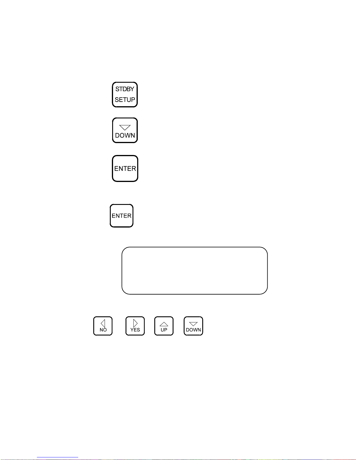
1.3. Keypad Functions
cursor to the left
answer <NO>
cursor to the right
answer <YES>
cursor upwards
scroll upwards
increase values
cursor downwards
decrease values
confirm entry
activate cursor position
read memory contents
start decoding
display memory contents
switch on back-lighting
start printing
select (P) print and/or (W) write
print space
return to higher menu level
end process
return to standby mode
gSET UP menu

1. Receiver
1.1. Operation
The receiver requires practically no operation.
The NAVTEX frequency (518.0 kHz) is pre-programmed
Further this model has one further pre-programmed frequency,
according to a defined sailing region.
The frequencies of a transmitting station are normally set down
internationally and are rarely changed. However, this pre-
programmed frequency has been allotted the following
parameters:
Morse
RTTY
SITOR-FEC
The message decoding mode has not been laid down, as it is
expected, that, in the next few years, various stations will change
their transmission from Morse or RTTY to SITOR-FEC. On the
following pages you can find a list of the present codes used.
It is not necessary to adjust the mode in the receiver. This is done
automatically, when selecting the decoding mode.

3. Decoding of Messages
The FMD15 can store and decipher NAVTEX, MORSE, RTTY and
SITOR codes, which then can be read and/or printed out in plain
language. In radio signal traffic there are many other kinds of
keyed codes. As they are not for use by the general public, they
cannot be decoded by the FMD15.
Weather and navigational warnings for shipping are transmitted
in one of the above-mentioned codes, which can be decoded
by the FMD15.
The signal tone (NF) received is fed to a PLL signal Decoder,
which filters out the audio signals and transforms them into digital
information. This in turn will be converted into legible symbols by
the integrated microprocessor.
The type of code used by the individual station, can be found in
the appropriate manuals for marine radio stations. The codes
used vary:
for MORSE also : CW,A1,A1A, telegraphy
for RTTY also : F1B, telex
for SITOR also : FEC,F1B
3.1Selecting Mode and Decoding
In various manuals, the type of code used by a station is shown
mostly as A1A, F1B etc. The following list is an oversight of types of
transmission generally used in marine radio transmission. The
required adjustments to receiver and Decoder are also listed

Message Transmission Types
Transmission receiver
decoder
Mode setup set
up
A1A – Morse-telegraphy
with non-damped carrier e.g.
Roma
CW
Morse
A2A - Morse – Telegraphy
in double side band method
CW
Morse
A3A – audio radio in
Double side band e.g.
BBC, DLT etc.
*
*
F1B – FM telex signal
From Pinneberg
FSK
RTTY
F1B – FM telex special
Signal for NAVTEX
FSK
SITOR-
NEC
F1B – FM telex (MSI
Frequencies e.g. Portishead:
4211kHz(402)
FSK
SITOR-
NEC
F1C – FM tele-facsimile
From Bracknell Pinneberg
Etc
FSK
*
F3E – VHF audio radio from
88kHz to 108kHz * *
H3E – AM radio, SSB with
Carrier e.g. Murmansk * *
J3E – SSB radio * *
R3R – as H3E however with a
Reduced carrier e.g. Niton * *
* - not available with FMD 15

3.2.Programming the Channels.
Press to enter set-up menu
Point cursor with key<DOWN> to 5: channels and press
<ENTER>.
Display shows:
CODE : RTTY
STORE : YES
PRINT : YES
The following parameters can be assigned to each channel:
Mode CODEMorse,RTTY,
SITOR
store decoded messages STORE YES/NO
print out decoded messages PRINT YES/NO
This is done as follows:
using <UP> and <DOWN> point cursor to select the
appropriate column ((CODE, STORE, PRINT).)
press <ENTER> at selected column. To select type of code,
scroll with the same key to shift from RTTY to SITOR to Morse
and return to RTTY and so on.
to select STORE and PRINT use <ENTER> similarly to select
between N(NO) and Y(YES)
YES - in column STORE means that the message will be stored
YES - in column PRINT means that the message will be printed
out simultaneously.
After checking that the parameters and the desired set up is
correct, return to NAVTEX standby mode by pressing <EXIT>
twice.

3.3 Recalling Stored Channels
to recall a channel press twice
the following picture appears on the display:
__
147kHz CH01
RTTY 50 Bd
This means that the receiver is receiving the pre-programmed
frequency. The bottom line shows that the code being used is
RTTY (Radio Tele Type) at a transmission rate of 50 Baud/m.
After a short phase for the decoder to synchronise, the
decoded text will appear on the top line.
According to the selected mode in 3.2., the decoded text can
only be read in the display or stored in the memory and
printed out.
The selection can be altered by pressing key <PRINT>. The
following functions for selection will appear on the bottom line:
_ _ display only
P _ display and print simultaneously
_ S display and store simultaneously
P S display, store and print
simultaneously.
This will not influence the mode selection in 3.2.

3.4.
Message Memory
The FMD15 possesses two separate independent memory
stores. One for NAVTEX messages (see chap.5) and one for
Morse, RTTY and SITOR messages.
The latter has a capacity of about 15000 characters. A
message of maximum 3750 characters can be stored in a
data record. Should a message be longer, further data
records will be automatically opened. All in all, 100 data
records can be filed with a total capacity of 15.000
characters. Should the memory store be full, a new message
will be stored by replacing the oldest messages.
The most up-to-date messages will always be available.
It can happen that a new message of only a few characters
replaces the oldest message containing 3750 characters. At
this moment the store contents have been reduced to 11250
characters.
On completion of the message, every data record will be
stored with a identification in form of date and time
(TTMMhhmm).
Should the FMD15 be switched off during storage, whether
deliberately or not (e.g. power interruption), the actual data
record will not be stored because of lack of signal ending.
Because of strong disturbance (e.g. starting the motors with
weak batteries), it can happen that the identification of data
records may be partly or completely deleted. In this case, it
may be possible to read messages only partly or not at all. On
restarting the unit it can happen that all messages in the
memory are deleted for safety reasons, because the unit
cannot recognise the identifications.
Thereafter newly decoded messages will be stored correctly.

4. Automatic Reception and Decoding
The FMD15 has a timer function for the storage of 9 programmes.
Each storage contains a starting time, stop time and the channel
number of a stored frequency (similar to that in a video
recorder). The transmission times of weather messages can be
found in the usual manuals but to be on the safe side it is
recommended to add some time before and after the start/stop
times.
For reference the following transmission times can be used:
MORSE transmissions approx. 30 mins.
RTTY transmissions approx. 15 mins.
SITOR transmissions approx. 10 mins
The FMD15 will automatically switch to the required frequency at
the selected start time and will decode according to the input
parameters. The decoded message will be stored, according to
the parameters, in the assigned channel if "STORE" was answered
with <YES>. It will be directly printed out if "PRINT" was answered
with <YES>.
On reaching the stop time, the FMD15 will switch back
automatically into standby mode i.e. the basic mode for NAVTEX
reception).
4.1. Programming the Timer Function
Starting from standby mode:
press key to call up menu 1
use key to select TIMER
press
4.1.1. Input of New Timer ON/OFF Times
press once more
On the display will appear:
INSERT ROW
from to
12:00 12:00
Use the cursor keys
to enter the required start and stop times and the channel
number. The keys <NO> and <YES> move the cursor to the
required position. The keys <UP> and <DOWN> change the figure
value.

Keys <UP> and <DOWN> have an auto-repeat function, which
means the selected value will increase or decrease in steps as
long as the key is depressed. As long as you have not pressed
<ENTER> you can change the value as often as required.
Having checked that all values are correct press <ENTER>. By
pressing <ENTER> once more you can enter further programme
rows.
4.1.2.
Deleting Timer ON/OFF Times
Call up TIMER menu as in 4.1.
Press key
On display will appear:
DELETE ROW NO. : 1__
Use the cursors <UP> and <DOWN> to select the number of the
row to be deleted and activate by pressing <ENTER>. To leave
the TIMER mode without a row deletion, press <EXIT>.
Press <EXIT> once more to return to the standby mode
The maximum length of time in the timer function is 60 minutes.
However it is possible to put in the same start time as the previous
stop time. In the case where to programmed times overlap, the
newer start time is dominant
Should a timer function be interrupted my manual operation e.g.
calling up another frequency, the unit will still return to standby
mode on reaching the stop time

4.2. Interrupting and Restarting the Timer
An actual timer programme can be interrupted by pressing the
<STDBY> key. The unit will switch back automatically to the standby
mode at the respective stop time. It is possible to restart the unit
during operation by switching it off for approx. 3 to 5 seconds.
When switched on the unit returns to its programmed status.
4.3 Reading Stored Messages
Stored messages can be read on the display as often as desired.
The complete data record store disposes of more than 20000
characters. Of this amount approx. 5500 are reserved for NAVTEX
messages, the rest for Morse, RTTY and SITOR together. When the
storage space is full, the oldest message will be automatically
deleted. However this is done separately for NAVTEX and other
messages. Meaning that the oldest NAVTEX message cannot be
replaced by a new RTTY message, only by a new NAVTEX message
and vice versa. Each message is identified by date and time in the
following form: TT.MM.HH.MM (day, month, hour, minutes).
Press key to recall READ MEMORY
use keys and to select the type of
message to be read (NAVTEX or CHANNEL) and press <ENTER>.
press key once more

The display will now show, when in NAVTEX, the list of messages with
NAVTEX identification (e.g. JA34), and when in CHANNEL the
display will show the stored messages by date and stop time in
number sequence DD.MM.HH.MM (Day, month, hour minutes).
Place cursor on selected message.
now press the key and the selected message
appears on the display.
keys <UP> and <DOWN> enable you to "turn the pages". On
reaching the end of the message or by pressing <EXIT>,the read
out will end.
by pressing <EXIT> once more you will return to standby mode.
4.4 Printing Out Stored Messages
Stored messages can be printed out as often as required.
Select the message to be printed out as READ MEMORY (see 4.3.)
press key to call up READ MEMORY
select message to be printed out
by pressing key the message will be
printed out from start to finish.
Printing can be stopped by pressing <EXIT>
It is possible to print only a part of the message e.g. only the sector
applicable to your sailing region. This is done as follows:
press key<DISPLAY> and message appears on display.

"turn the pages" with the cursors <UP> and <DOWN>
by pressing <PRINT> the printer will commence from the
displayed page
press <EXIT> when required or allow printing to continue until the
message has ended
press <EXIT> twice to return to standby mode

5. NAVTEX, Reception and Decoding
When the unit is in standby mode, it is automatically operating as a
NAVTEX receiver and therefore a manual activation is not
necessary
ATTENTION:
During the reception of other stations, also when receiving a
message programmed to be stored by the timer, NAVTEX
cannot be received.
However, depending on your position, you should put in the
necessary system parameters to enable the best possible NAVTEX
information.
In put of the parameters is done as follows:
press key <SET UP> to call up set up menu
with cursor <DOWN> spring to position 4 - NAVTEX
press <ENTER> to enter NAVTEX menu
Display will show
1 FREQU. 5 REPEAT
2 STATION 6 ALARM
3 MESSAGE 7 STATUS
4 PRINT 8 EXIT
Table of contents


