Fastrax Hellfire 900 Guide

Part No. HF18948.Rev.3.04 November 2018 Printed in Canada
ANSI Z83.7-2017 / CSA 2.14-2017
Gas Fired Unvented Construction Heaters (Unattended Type)
IMPORTANT INSTRUCTIONS - SAVE THESE INSTRUCTIONS
Read all instructions before installing or using the heater. Please adhere to instructions published in this manual.
Failure to do so may be dangerous and may void certain provisions of your warranty.
Fastrax®is a registered trademark of Thermon Heating Systems, Inc.
Copyright©2018. All rights reserved.
ISO 9001
2014
HELLFIRE 900
Gas Fired Railway Switch Heater
Installation, Operation, & Maintenance Instructions

TABLE OF CONTENTS
A. Important Notices And Warning Symbols 4
B. Identification 6
B.1 Heater Labels ........................................................6
B.2 Model and Serial Number Tag...............................6
B.3 Components Diagram...........................................6
B.4 Control Panel Diagram - 240V Single Phase
Example Shown ....................................................7
B.5 Gas Manifold Diagram...........................................7
C. Pre-Operation Inspection 8
C.1 Important Notices..................................................9
C.2 Prior to Heater Start-Up ........................................9
D. Operation 11
D.1 Introduction......................................................... 11
D.2 Modes................................................................. 11
D.3 Start-Up Sequence (All Modes)........................... 11
D.4 Occurrences During Normal Operation ............... 11
D.5 Heat Output Adjustment ..................................... 11
E. Controls & Indications 13
E.1 AAR Signal Wiring - For non SCADA installations 13
E.2 Controller.............................................................13
E.3 Controls...............................................................14
E.4 Indications ...........................................................14
E.5 Terminal Blocks ...................................................15
E.6 Data Communications.........................................16
E.7 Controller EEPROM Memory ...............................16
E.8 Activating a COMMUNICATION Parameter..........16
E.9 Mode Parameters ................................................16
E.10 Activating MODE Parameter................................. 17
E.11 Fan Mode.............................................................17
E.12 Local EMS Mode.................................................. 17
E.13 RAIL THERMOSTAT Mode, Normal...................... 17
E.14 RAIL THERMOSTAT Mode, Reverse ....................17
E.15 Failure Shutdowns and Alarm Indications.............17
E.16 Fault Conditions ................................................... 17
E.17 Aggressive Retry Feature .....................................18
E.18 R e s et ...................................................................18
E.19 Energy Management System (EMS).....................19
E.20 Terminal Blocks ...................................................20
E.21 Inputs and Outputs..............................................20
F. Troubleshooting 21
G. Installation 25
G .1 O v e r v i e w .............................................................25
G.2 Recommended Tools..........................................25
G.3 Site Preparation - Typical Clearances .................25
G.4 Site Preparation ..................................................28
G.5 Heater Installation ...............................................28
G.6 Gas Supply Piping and Minimum Pressure Drop 28
G.7 Electrical Power Connections .............................28
G.8 Power Connections ............................................29
G.9 Thermostat Installation........................................31
G.10 Energy Management System (EMS) Options .....31
G.11 Inspection and Commissioning............................34
H. Heater Specifications 35
H .1 P e r f o r m a n c e........................................................35
H.2 Gas Firing............................................................35
H.3 Gas Conversion ..................................................35
H.4 Electrical .............................................................35
H.5 Controls ..............................................................35
H.6 Wiring Terminations.............................................35
H.7 Safety Features ...................................................35
H.8 Controller Terminal Identification .........................36
H.9 SchematicsMaintenance.....................................37
I. Maintenance 43
I.1 Thermostat Removal .............................................43
I.2 Motor/Impeller/Base Removal...............................43
I.3 Impeller Removal ..................................................43
I.4 Flame Rod and Spark Igniter Removal..................44
I.5 Burner Removal....................................................44
I.6 Burner Defroster Removal.....................................44

J. Service 45
J.1 Recommended Service Schedule........................45
J.2 Gas Supply Pressure ...........................................46
J.3 Gas Supply Leak Test ..........................................46
J.4 Manifold Leak Test...............................................46
J.5 Main And Safety Gas Solenoid Valves Leak Test .47
J.6 Dirt Trap And Strainer ..........................................47
J.7 Motor ...................................................................47
J.8 Vibration Specifications and Measurement..........47
J.9 Lubrication...........................................................47
J.10 Flame Safety Relay (FSR)......................................47
J.11 Flame Signal.......................................................48
J.12 Air Switch .............................................................48
J.13 Air Switch Calibration .........................................48
J.14 High Temperature Limit ........................................48
J.15 AAR Terminals, Signals, and Communications.....49
J.16 Burner ..................................................................49
J .17 D e f r oste r ..............................................................49
K. Parts 50
K.1 Parts - Heater Body.............................................50
K.2 Parts - Control Panel, 240V Single Phase............ 51
K.3 Parts - Control Panel, 208V Three Phase ............51
K.4 Parts - Control Panel, 460V/575V
ThreePhasewith120V Duplex Receptacle .........52

4
4
Important Notices and Warning Symbols
A. IMPORTANT NOTICES AND WARNING SYMBOLS
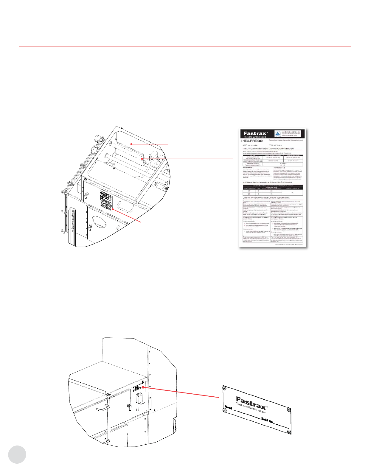
Keep this manual with the machine at all times. The purpose of
this manual is to provide owners, operators, and installers with
the precautions and procedures essential for the safe and proper
operation for its intended purpose.
WARNING
CAUTION. This symbol indicates a potentially
hazardous situation, which, if not avoided, may result in
personal injury or damage to the equipment.
WARNING
WARNING. This symbol indicates an imminently
hazardous situation, which, if not avoided, can result
in serious injury or damage to the equipment.
.
WARNING
WARNING. Read and adhere to the following. FAILURE
TO DO SO MAY RESULT IN SEVERE OR FATAL
INJURY. Warranty will be void.
NOTE: “NOTE:” indicates information or a company policy that
relates directly or indirectly to the safety of personnel or
protection of property.
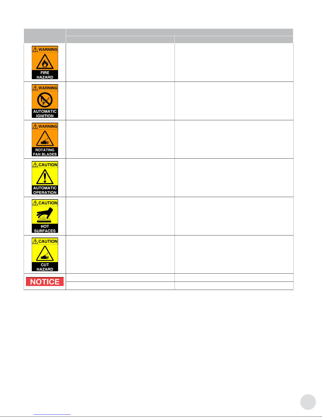
Table 1 – Operation Warning/Avertissements (Intended for Signal Maintainers)
Symbol Description
English French
Risk of electrical shock or electrocution.
Disconnect electrical power prior to servicing.
Risque de choc électrique ou d’électrocution.
Couper le courant avant d’entreprendre l’entretien.
The heater is designed and approved for use as a
commercial heater (gas) – railway switch, class 2902 05
in accordance with ANSI Z83.7 / CSA 2.14. Check with
local authority, if you have questions about applications.
Cet appareil a été conçu et approuvé pour être utilisé comme
radiateur commercial (gaz) - aiguillage de voie ferrée de
classe 2902 05, conformément à la norme ANSI Z83.7 / CSA
2.14. Communiquez avec les autorités locales pour plus de
renseignements sur le lieu d’utilisation de cet appareil.
General hazard warning failure to comply with the
precautions and instructions provided with this heater,
can result in death, serious bodily injury and property
loss or damage from hazards of re, explosion, burn,
asphyxiation, carbon monoxide poisoning, and / or
electrical shock.
Only persons who can understand and follow the
instructions should use or service this heater. If you
need assistance or heater information such as an
instructions manual label, etc. Contact the manufacturer.
Mises en garde générales le non·respect des mises en garde
et des instructions fournies avec ce radiateur peut entraîner
la mort, des graves blessures et des pertes matérielles ou
des dommages à la propriété résultant d’un incendie, d’une
explosion, de brûlures, d’asphyxie, d’empoisonnement au
monoxyde de carbone et/ou d’un choc électrique.
Seules les personnes aptes à comprendre et à suivre les
instructions devraient se servir de ce radiateur ou le réparer.
Si vous avez besoin d’aide ou d’informations concernant ce
radiateur, soit une notice d’instructions, une étiquette, etc.,
Prière de communiquer avec le fabricant.
Fire, burn, inhalation, andexplosion hazard. Keep solid
combustibles, such as building materials, paper, or
cardboard, a safe distance away from the heater as
recommended by the instructions. Never use the heater
in spaces which do or may contain volatile or airborne
combustibles, or products such as gasoline, solvents,
paint thinner, dust particles or unknown chemicals.
Risque d’incendie, de brûlures, d’inhalation et d’explosion.
Garder les combustibles solides, tels les matériaux de
construction, le papier et le carton, à bonne distance de ce
radiateur, comme il est recommandé dans les instructions.
Ne jamais utiliser cet appareil dans des endroits qui
contiennent ou pourraient contenir des combustibles volatiles
ou en suspension dans l’air tels l’essence, les solvants, les
diluants pour peinture, les particules de poussières ou des
produits chimiques inconnus.
Not for home or recreational vehicle use. Ne pas utiliser dans une maison ou un véhicule de camping.
All persons employed in handling propane or natural
gas shall be trained in proper handling and operating
procedures, as required by local authorities having
jurisdiction.
Toute personne qui manipule le propane ou le gaz naturel
doit avoir suivi une formation sur les bonnes procédures de
manipulation et d’utilisation qui est conforme aux exigences
des autorités locales compétentes.

5
Important Notices & Warning Symbols
Symbol Description
English French
If you smell gas; immediately extinguish all sources of
ignition and turn off gas source. Call qualied service
technician to repair leak.
S’il y a une odeur de gaz : fermer immédiatement toute
source d’allumage et de gaz. Faire réparer la fuite par un
technicien qualié.
Do not attempt to manually light burner.
Heater equipped with an automatic electronic ignition
system.
Ne pas allumer le brûleur manuellement.
Radiateur équipé d’un système d’allumage électronique.
Risk of cutting ngers or hand.
Disconnect fan power prior to removing combustion
chamber access panel or air intake.
Risque d’amputation des doigts ou de la main.
Couper le courant au ventilateur avant d’enlever le panneau
d’accès à la chambre de combustion ou l’entrée d’air.
Heater can start automatically.
Exercise caution when in close proximity.
Attention : le radiateur peut démarrer automatiquement.
Faire preuve de prudence près du radiateur.
Burn hazard / hot surfaces.
Do not touch track ducts, nozzles or any non-insulated
duct connected downstream of heater during operation.
Surface chaude; risque de brûlure.
Ne pas toucher les conduits latéraux à la voie ferrée, les
buses ni aucun conduit non isolé branchés en aval d’un
radiateur en marche.
Sheet metal edges can be sharp.
Wear protective clothing when handling track duct,
insulted ducts and any other sheet metal components.
Risque de coupure.
Les rebords de la tôle sont coupants. Porter des vêtements
protecteurs lors de la manipulation des conduits isolés et tout
autre composant en tôle.
For use with ductwork only. Pour utilisation avec réseau de gaines seulment.
Retain manual for future reference. Conserver le manuel pour consultation ultérieure.

6
6
B. IDENTIFICATION
B.1 Heater Labels
1. Each heater has a ratings label, a logo label, a model and
serial number tag and a voltage label.
2. The ratings label contains all identication and safety
information. It is fastened by a lanyard and stored in the
manual pocket inside the control enclosure next to the gas
manifold. The electrical specications are indicated with a
punch mark.
3. The logo, located on the side of the air intake hood
identies the series as HELLFIRE, and the size, either 400
or 900.
4. The model / serial number tag is a blue aluminum plate.
The model number is applied to an adhesive backed label
bonded to the tag, and the serial number is engraved. The
serial number is a sequential 6-digit number.
Installation & Instruction
Manual Location
Voltage Label
Rating Label
B.2 Model and Serial Number Tag
1. The tag is located on the front and above the selector
switch.
2. This is true for all congurations including heaters supplied
with the bungalow option.
3. Congurations are identied on the tag as model “HF 900”
followed by a 5-digit number, an optional 2-digit dash
number and a revision letter. For example,
HF900 12345-01A (HF900 BUNG XXXXX-XXX - for
bungalow enclosed heaters).
4. The operating voltage label is found on the electrical
access panel. Have this information available when
requesting parts or service.
B.3 Components Diagram
5. The following component names are referred to in this
manual. See Section L - Parts for part numbers and
ordering.
Stand-Alone & Bungalow Enclosed Configurations
Identification Tag with Model and Serial Number
Identication

77
Identication
B.4 Control Panel Diagram - 240V Single Phase Example Shown
B.5 Gas Manifold Diagram
No. Label
1Track duct
2 Track duct elbow
3Rail mounting spring clip and pad
4Ballast retainer
5Thermostat box
6Precipitation detector
7Burner
8Regulator vents
9Condensation vent
10 Gas manifold
11 Control cabinet lid
12 Air intake hood
13 Ambient air temperature sensor
14 Air intake extension
15 Identication tag
16 Mode selector switch
17 Electrical control access panel
No. Label
18 Air intake plenum
19 Leveling leg
20 Control panel
21 Motor/Impeller/Base
22 Combustion chamber access panel
23 Transition duct
24 Sensor duct
25 Square to round adapter
26 Flex duct
27 Track duct deector
28 Tie duct
29 Rail thermostat
30 Point nozzle
31 Track duct mounting bracket
No. Label
1Ignition transformer
2Burner control / Flame Safety Relay
3 Purge timer card
4Reset module
5Controller
6Programming key
7EMS module
8Control circuit breaker
9 Motor circuit breaker
10 120V receptacle
11 Contactor
12 Control transformer
13 Power terminal block
14 Mode selector switch
15 Hour meter
16 Receptacle circuit breaker
17 Tank valve circuit breaker
18 Control and indication terminal block
19 Resettable fuse, burner defroster
20 Manifold terminal block
21 Rail thermostat receptacle
22 Precipitation detector receptacle
23 Flame signal amplier

8
8
C. PRE-OPERATION INSPECTION
Identication
No. Label
1Regulator vent
2Regulator vent pipe
3 Pilot gas solenoid valve
4Pilot gas pressure regulator
5Pilot manual shutoff valve
6Gas supply inlet
7Gas supply pressure gage
8Main gas pressure regulator
9 Main and safety gas
solenoid valves
No. Label
10 Manifold gas pressure gage
11 Main manual shutoff valve
12 Union
13 Burner mounting bracket
14 Burner defroster
15 Igniter
16 Flame rod
17 Burner

99
Pre-Operation Inspection
C.1 Important Notices
To ensure trouble free operation during the winter months, inspect
the system annually at the start of the season.
WARNING
WARNING. All persons employed in handling propane
or natural gas shall be trained in proper handling and
operating procedures, as required by local authorities
having jurisdiction.
Gas leaks shall be repaired immediately or, gas supply
valve closed until repairs can be made.
All work performed on railway property must be
carried out in accordance with local railway authorities
instructions.
CAUTION
CAUTION. Do not operate this machine until it has
been installed and commissioned according to
requirements specied in the installation section of this
manual.
NOTE: Perform inspection and operations in accordance with
the instructions provided in the service section of this
manual.
NOTE: This inspection guide assumes that all applicable service
bulletins have been implemented on the heater being
inspected.
NOTE: The outcome of any inspection items that differ from that
expected indicates further service is required.
C.2 Prior to Heater Start-Up
Table 2 – Heater Inspection List
Inspect Action
Condition of all ducting, particularly any
ex ducts Repair or replace damaged ductwork.
Inside of all tie duct and cross ducts Remove any blockages, such as debris and mud.
Track duct vents Close vents that do not direct air at tie plates or rods.
Set vent openings to 1/8” - 1/4” maximum.
Track duct mounting Verify track ducts do not interfere with normal movement of the switch points and do not interfere
with the signal system.
Flame rod and spark igniter
Remove and visually inspect for cracks in the ceramic, and evidence of soot. Replace any with
cracked ceramic.
If evidence of soot is found, clean rod and investigate condition of burner, gas manifold, and
inspect tie duct, cross ducts and air intake for blockage.
Flame rod and ignition wires Inspect boot for degradation, cracks and poor seals. Replace if necessary.
Inspect connectors for signs of corrosion. Clean connections, or replace wire if necessary.
Combustion chamber Verify it is clear of any obstructions or debris, ie. animal nests.
Cycling and high limit thermostat
installation
Verify thermostats are fastened and are in full contact with duct surface.
Replace any with damaged wire insulation.
Verify thermostat enclosure is sealed and dry inside.
Service surge protection Verify electric service has functioning surge protection.
Air switch port and vent Remove any obstruction.
Gas regulator vents Remove any obstruction.
Flame Safety Relay Verify it is installed and is in standby mode with ‘POWER’ LED blinking, and ‘ALARM’ LED off.
Gas source Verify propane tank is lled, or natural gas service is open and has pressure.
Open all manual gas shut off valves and inspect all gas lines for leaks.
Electrical service Verify electric service power is on. Close supply circuit breakers.
Flame Safety Relay Burner Control fault
histories
Using Honeywell display module S7800A1001 (Part number 9040-0021). Review and record the
last 6 stored fault history error codes. See Honeywell manual for description of faults.
H1 Code Hour Cycle
H2 Code Hour Cycle
H3 Code Hour Cycle
H4 Code Hour Cycle
H5 Code Hour Cycle
H6 Code Hour Cycle

10
10
Pre-Operation Inspection
Inspect Action
Electrical supply Verify correct line voltages at each heater. Must be within +/- 5% of nominal voltage.
Verify current draw is less than or equal to nameplate rating.
Gas supply Verify supply and manifold gas pressures are within nameplate limits when heater and all
connected loads are operating.
Flame signal strength
Verify ame signal strength is stable (+/- 0.5) and between 3.0 and 5.0 Vdc.
If signal strength is low:
– Clean or replace ame rod.
– Clean ame rod wire connections, or replace wire.
If cleaning or replacement of ame rod and wire does not increase strength, have burner serviced
or replaced.
Burner operation
Note current manifold pressure.
Set manifold pressure to maximum nameplate setting, measure point nozzle temperature, if
point nozzle temperature is 140°F or less above ambient air temperature have burner serviced or
replaced.
Return manifold pressure back to desired setting.
Air switch calibration
Block air intake 80%. Verify heater still operates.
Then block 90% and verify FSR alarms.
If heater fails with 80% or less blockage, recalibrate air switch.
Control and indication wiring Verify the correct control and indication wiring between the heater and the signal bungalow.
Energy Management System (EMS)
If heater is operated automatically by an Energy Management System:
– Verify EMS module is installed and connected with POWER LED lit.
– Verify controller is in AUTO mode.
– Verify precipitation detector and ambient temperature sensor installed and connected.
– Verify rail thermostat is mounted on rail and connected to surge isolator.
– Verify its operation.
Aggressive retry
Verify operation.
Turn gas supply off, toggle heater to “Manual”.
Verify three attempts made followed by lockout.
Return heater to desired operating mode.
Open gas supply.
Reset controller.

1111
Operation
D. OPERATION
D.1 Introduction
The switch heater is a gas red, hot air heating system that
keeps a turnout clear of ice and snow during winter storms
by blowing hot air, between the stock rail and moving
points, at the tie plates on which the points slide, and at the
gage rods.
D.2 Modes
The heater can be operated in the following modes:
1. MANUAL - by toggling the mode selector switch
to “MANUAL”, the heater will turn on and operate
continuously. If installed, the rail thermostat will cycle
the burner on and off as required to maintain the rail
temperature.
2. AUTO – With the controller congured for LOCAL AUTO
MODE, toggling the mode selector switch to “AUTO/
REMOTE”, and with an EMS module, precipitation and
ambient temperature sensor installed, the heater will turn
on or off as required based on the weather conditions. If
installed, the rail thermostat will cycle the burner on and
off as required to regulate the rail temperature.
3. REMOTE RTC- by toggling the mode selector switch
to “AUTO/REMOTE” and with a Rail Trafc Control, RTC
(dispatcher) operated control relay contact wired to
terminals A1 and A2 of the control and indication terminal
block. With RTC timer disabled, the heater will operate
continuously while the RTC contact is closed, if the RTC
timer is enabled, the heater will run for the duration of
the RTC timer then stop. RTC can restart the heater for
additional run time by resetting the request. If installed, the
rail thermostat will cycle the burner on and off as required
to maintain the rail temperature.
4. REMOTE SCADA - With the controller congured for
REMOTE SCADA MODE, toggling the mode selector
switch to “AUTO/REMOTE” with the heater connected
to a Supervisory Control and Data Acquisition, SCADA,
network via the controllers’ RS-485 communications port,
and congured with a Remote Control and Monitoring
System (RCMS), software, the heater will operate
automatically.
If installed, the EMS module, precipitation detector,
ambient temperature sensor and rail thermostat provides
inputs to the RCMS software.
5. OFF – to disable the heater, toggle selector switch to
“OFF”.
D.3 Start-Up Sequence (All Modes)
Once a start request is received the control sequence begins.
NOTE: If the controller is in ‘REMOTE RTC’ mode then it waits
for the ‘DELAY START’ time before initiating.
Table 3 – All Modes
Conditions/Sequence Status LED
Heater is in an operational mode not OFF. ENABLE
Cycling thermostat is cold or closed. CYCLING
Motor contactor closed, fan starts. MOTOR
Air pressure develops, air switch closes. AIR SW
FSR requested, trial for ignition, burner lit. HE AT
Main gas valve opens. FSR CHECK
Run indication contact closed. RUN
To conrm the heater operation, the burner remains lit and the rail
thermostat status is ignored for the rst 2 minutes.
Normal operation Heater runs as long as requested.
D.4 Occurrences During Normal Operation
NOTE: The rail thermostat closes when the rail temperature is
above 9°C (49°F) and opens when below 3°C (37°F).
6. As long as the rail is cold and the thermostat is open, the
burner remains lit. Once the rail warms and the thermostat
closes, the burner is extinguished. This cycle repeats as
required while the heater operates. If the rail temperature
remains warm for more than the post purge time then the
fan is turned off. The run indication is maintained during
this time.
7. If the heater is in ‘REMOTE SCADA’ mode and the
‘Fastrax® RCMS’ software is requesting performance
operation, the burner will remain lit regardless of rail
thermostat status.
NOTE: The cycling thermostat limits the heated air temperature
to a maximum of 193°C (380°F). Under normal
circumstances the air temperature remains below this
limit.
8. If the heated air temperature becomes excessively hot,
the cycling thermostat limit opens, and the burner is
extinguished immediately. Once the air cools and the
thermostat closes the burner is lit and heating resumes.
Run indication is maintained during this time.
D.5 Heat Output Adjustment
1. Depending on the length of switch points, its’ priority,
local climate conditions, and experience, the operator
can increase or decrease the heat output accordingly.
The recommended heat output is in the range of 10,000
to 22,000 BTU/hr per foot of turnout length.

12
12
Operation
2. The factory default setting is 550,000 BTU/hr when
operated on LPG, or 390,000 BTU/hr on NG.
3. The heat output can be adjusted as follows:
3.1 With the heater running, unscrew and remove the
main regulator (8) cap.
3.2 Use a at blade screwdriver to turn the internal nut
clockwise to raise (shown) or counterclockwise
to lower pressure as indicated on the manifold
pressure gage (10).
3.3 Screw cap closed.
3.4 As a starting point, with the heater operating,
adjust the manifold gas pressure to attain an air
temperature of 121°C (250°F) above ambient as
measured at the near point nozzle.
WARNING
WARNING. Do not operate above maximum manifold
pressure as this can produce carbon monoxide in
excess of maximum allowable of 0.08 AFCO.
WARNING
WARNING. Do not operate above or below the rated
manifold pressure limits. Operating outside limits will
result in weak ame signal and unreliable operation.
WARNING
WARNING. Install cap once regulator adjustment is
complete. In the event of pressure relief, the cap must
be closed to vent gas to the exterior.
3.5 The heat output can be estimated from the manifold
pressure and the following formulas:
204,000 + ((Manifold pressure –2.5)/6.5)*696,000 for LPG or
230,000 + ((Manifold pressure –3.5)/12.5)*670,000 for NG
Pressure is in inches of water column.
NOTE: These formulas are simplied, assume the equipment is
in good condition, and are strictly for estimation only.

1313
Controls & Indications
E. CONTROLS & INDICATIONS
E.1 AAR Signal Wiring - For non SCADA installations
Table 4 – AAR Signal Wiring
Terminals Label Description
A1 - A2 REMOTE START A contact closure across these terminals starts the heater when the heater is in REMOTE RTC mode.
A3 - A4 RUN Dry contact closes to provide a run indication.
A5 - A6 ALARM Dry contact closes to provide alarm indication.
A7 - A8 FORCE OFF Default is closed. If FORCE OFF function is desired, remove shorting link and replace with customer
supplied relay contact. Open contact disables heater.
A9 - A10 TANK VALVE These terminals are intended to operate a 120V AC gas supply solenoid shut off valve. They energize
when the motor contact closes.
A11 RS-485 (+) Communications, RS-485 positive terminal (for RCMS operation only)
A12 RS-485 (-) Communications, RS-485 negative terminal (for RCMS operation only)
E.2 Controller
1. The controller manages the operation of the heater and
allows it to either operate on its own or be part of a
network of heaters.
2. The controller monitors various inputs, controls the heater
functions, communicates status and provides indication
LEDs.
3. The controller is DIN rail mounted and all wiring
connections are made with plug connectors to allow quick
replacement in the event of a failure.
4. With the addition of the EMS package, a stand alone
heater can operate automatically based on weather
conditions, or when connected to a network, act as a
weather station providing input to a SCADA system.
5. Its’ RS-485 serial communications port allows the heater
to interface with SCADA systems, and be operated and
managed by a Remote Control and Monitoring System,
such as the Fastrax® RCMS.
NOTE: Controllers are not interchangeable between HELLFIRE
400 (24VAC) and HELLFIRE 900 (120VAC).

14
14
Controls & Indications
E.3 Controls
1. Power: This switch turns the power supply to the board
‘ON’ or ‘OFF’.
WARNING
WARNING. 120VAC inputs to controller can remain
energized.
2. Reset: This push button is used to reset the controller in
case of a lockout.
3. Delay Start: This dial sets the length of the delay, 0 to 60
seconds, before starting the heater. It is intended to allow
the stagger start of multiple heaters connected to one
power service thereby reducing the maximum current
draw. This setting is true for REMOTE RTC mode only.
Under MANUAL, AUTO and REMOTE SCADA modes
there is no delay.
NOTE: This setting is overridden when operated in REMOTE
SCADA mode by the corresponding Fastrax® RCMS
software parameter.
4. Post Purge: This dial sets the length of the delay, 5
seconds to 4 minutes, once the heater is no longer
requested, before stopping the fan. It is intended to purge
the remaining heat and moisture from the combustion and
duct system. This setting is true for all modes.
5. RTC Time: (RTC stands for Rail Trafc Control dispatch)
This dial limits the run time between 20 minutes to 4 hours,
when requested by RTC dispatcher, and with the RTC
SW switch ON, and the heater is in REMOTE RTC mode.
When the RTC request exceeds the time limit, the heater
turns off, and the run indication is maintained as long as
the heater is requested.
Timer is reset once the RTC request is removed. RTC can
then request the heater for another cycle.
It is intended to save fuel by avoiding unnecessary heater
operation by the dispatcher. This setting is true for RTC
MODE only. Under MANUAL, AUTO, and REMOTE SCADA
modes there is no limit.
6. RTC SW: This switch enables the RTC TIME function when
in the ON position. When switched OFF, RTC TIME is
disabled and the heater runs as long as requested.
7. JUMPER, JP1: Used to congure controller parameters.
E.4 Indications
1. On the controller are a number of status LEDs intended
to aid the user’s understanding of the heater state of
operation. See Table 6 - Controller LED Descriptions for
full description.
NOTE: With the exception of the communications TD, RD, and
TX LED’s. Solid green, solid green with a red pulse, or
yellow LED’s indicates normal status. Solid red and
alternating LED’s indicate a failure. This is true for the
controller only, not the EMS module.
2. Refer to Section F - Troubleshooting for explanation of
problem condition LED codes.
3. The LEDs listed can be found on the controller from top
left to bottom right on the board.
Table 5 – Controller LED Descriptions
LED Name Description State Indication
TD, RD, TX RS-485
communications
TD, RD on and pulsing
TX off and pulsing Heater in REMOTE SCADA mode.
TX off
TD and RD on Heater in LOCAL AUTO mode.
TD, TX off and pulsing
RD on 8N1 COM communications mode.
Status Processor status
Solid green with a red
pulse Normal operation.
Alternating red and
green FSR failure alarm. Aggressive retry mode in process.
Solid red
Failure alarm.
Note any alternating LEDs and refer to Section F - Troubleshooting.
Controller must be reset.
Solid green or off Processor has stopped functioning.
ENABLE Heater enable On Mode selector switch is either in MANUAL or REMOTE/AUTO position.
Heater can be started in AUTO REMOTE RTC or REMOTE SCADA modes.
Off Mode selector switch is in OFF position. Heater is in OFF mode and will not start.
FSR CHECK Flame Safety
Relay check
On Gas valve energised. Used to conrm correct operation of FSR.
Alternating The FSR did not energized the main gas solenoid valves when expected.
RES FSR Reset On Controller clears FSR alarm.

1515
Controls & Indications
LED Name Description State Indication
EMS REQ EMS request On EMS module request for heater to run.
Heater only acts on this request if in AUTO mode.
POWER Power supply On Controller energized.
MOTOR Motor On Contactor closed, motor turned on.
HEAT Controller
request for heat On FSR requested. Ignition sequence started or burner operating.
RUN IND Heater run
indication On Indication contact closed. Turns on after 60 seconds of normal operation.
ALARM Heater alarm
indication On Alarm indication contact closed. Heater off and locked out. Controller must be
reset manually.
FSR ALARM Flame safety
relay alarm
On FSR in ALARM, or controller is preventing its operation.
Alternating FSR is in ALARM. Heater failed 4 times in 5 minutes.
AIR SW Air pressure
switch
On Contact closed. Sufcient air ow to allow burner operation.
Alternating Air switch did not operate as intended. Air switch either did not close with fan ON
or did not open with fan OFF.
Off with pulse on Continuous fan mode with selector switch in OFF position.
On with pulse off Continuous fan mode with selector switch in MANUAL or REMOTE/AUTO
position.
CYCLING Cycling
thermostat
On Thermostat closed. Heated air temperature is BELOW set point.
Alternating Cycling thermostat open for more than 10 minutes.
HIGH LIM High limit
thermostat
On Thermostat closed. Heated air temperature ABOVE set point.
Alternating High limit thermostat closed momentarily indicating air temperature exceeded
set point.
MANUAL Manual operation On Selector switch in “MANUAL” position. Heater in MANUAL mode.
RAIL TH Rail thermostat On Thermostat open. Rail temperature is BELOW set point.
RTC Rail trafc control
mode
On Indicates selector switch is in “REMOTE/AUTO” position and AAR terminals 1
and 2 are closed.
Off with pulse on Indicates selector switch is in “REMOTE/AUTO” position and requested by
RCMS.
On with pulse off Indicates selector switch is in “REMOTE/AUTO” position and requested by
RCMS and AAR terminals 1 and 2 are closed.
E.5 Terminal Blocks
1. The controller interconnects with the control panel by means of 8 board level headers, TB1 to TB8, which accept the various
wire harness plug connectors. The controller and EMS module connect via a ribbon cable that plugs into the 10-pin header
found on each.
Table 6 – Terminal Block Description
Name Description
JP1 Jumper. Used to congure EEPROM settings
TB1 120V power, transformer primary and motor contactor coil output
TB2 Transformer secondary 24V power and FSR request output
TB3 RTC run and alarm indication contacts outputs
TB4 Rail thermostat, RTC request, Manual, and Enable inputs
TB5 Air switch, FSR/DSI alarm, gas valve inputs
TB6 Cycling and high limit thermostats inputs
TB7 Communication port, RS-485
TB8 FSR reset and current transformer inputs
10-pin header* EMS module power and signal connection
*Located in the upper right corner next to TB8.

16
16
Controls & Indications
E.6 Data Communications
1. The RS-485 serial communications port, and an
EEPROM, allows the heater to be part of a Supervisory
Control and Data Acquisition (SCADA) network and
Remote Control and Monitoring System (RCMS) software.
2. The RS-485 port runs at 9600 baud and allows
communication over long distances of up to 1000’ and
possibly longer.
NOTE: Cable construction: Cat5 24 AWG twisted pair is a very
common cable type used for RS-485 systems. Adding
shielding to the cable enhances noise immunity, and
thereby allows greater distance. If used, connect one
end only of shield to ground.
3. The 8-bit memory address allows a maximum of 254
heaters to connect to the same communications bus.
E.7 Controller EEPROM Memory
1. EEPROM memory chip stores parameters and an address.
2. EEPROMs can be switched between controllers. In the
event a controller needs to be replaced the EEPROM can
be removed from the old and put in the replacement. The
parameters and address remain with the heater and no
RCMS software modications are required.
WARNING
WARNING. Electrostatic discharge can damage ICs.
Have qualied personnel remove and install EEPROM IC.
3. Parameters activated locally or remotely by the RCMS
software are stored on the EEPROM.
NOTE: There are two parameter types, ‘COMMUNICATION’ and
‘MODE’.
Table 7 – Communication Parameters (Activated Locally)
Name Setting1Function
LOCAL AUTO MODE 1 Disables communications and
enables local EMS control.
REMOTE SCADA
MODE 2
Enables RS-485 MODBUS
communication.
Disables local EMS control.
Enables weather station mode.
DEFAULT ADDRESS 3 Writes 254 to processor address.2
ADDRESS SET 4 Writes new address to EEPROM 2
8N1 COM 5Enables 8N1 communication.3
Enables local EMS control.
LOCAL EMS, enabled 6Enables local EMS control.
LOCAL EMS,
disabled 7Disables local EMS control.
FAN MODE ----
When enabled, the fan runs
continuously.4
When disabled, the fan runs only
when heating is requested.
1Setting number equals alarm LED/relay count.
2One time functions.
3The 8N1 conguration allows the heater to send status information only
and is intended to aid service technicians. This conguration does not allow
the heater to be part of a network.
4See CONTINUOUS FAN MODE section for instructions.
E.8 Activating a COMMUNICATION Parameter
NOTE: Read and understand the following procedure before
starting. COMMUNICATION parameters require a
hardware programming key to make changes, MODE
parameters do not.
1. Toggle mode selector switch to “OFF”. If installed,
disconnect EMS cable from controller. Plug programming
key into the mating EMS 10-pin connector. Then the red
LED on the key lights.
2. Press the RESET button, and short jumper JP1.
3. Release the RESET button. The RTC, MANUAL, CYCLING,
and AIR SWITCH LEDs will each pulse, one after the other
for one sequence. Then the RUN indication LED pulses
and the green LED on the programming key alternates on
and off.
4. After ve RUN indication pulses, the red ALARM LED lights
for 3 seconds. This cycle continues as long as the jumper,
JP1, is shorted.
5. Count the number of times the red ALARM LED lights.
6. Once the count equals the parameter number, remove
the jumper before the ALARM LED turns off. For example,
when the ALARM LED lights for the second time
removing the jumper will activate REMOTE SCADA MODE,
parameter #2.
7. Function performed.
8. Parameter or new address is stored on the EEPROM.
9. Repeat sequence as required to activate other parameters.
E.9 Mode Parameters
Table 8 – Mode Parameters
Name Parameter1Function
FAN MODE
ENABLE 1Turns the motor on and keeps it
running continuously.
FAN MODE
DISABLE 2Motor runs only when heater is
requested.
LOCAL EMS
MODE
ENABLE
3 Local EMS controls the heater.
LOCAL EMS
MODE
DISABLE
4The local EMS will not turn the
heater on.
RAIL
THERMOSTAT
MODE NORMAL
5
Congures operation to new
thermostat, open when cold,
closes on temperature rise (COR).
RAIL
THERMOSTAT
MODE
REVERSED
6
Congures operation to older rail
thermostats that are closed when
cold, open on temperature rise
(OOR).
1Parameter number equals alarm LED/relay count.

1717
Controls & Indications
E.10 Activating MODE Parameter
NOTE: Read and understand the following procedure before
starting.
1. The controller must be powered on for a minimum of 60
seconds, the mode selector switch toggled OFF, and
terminals A1 A2 open (i.e. no RTC request).
2. Short jumper JP1. The RUN indication relay and LED
pulses on and off. After ve RUN indication pulses, the red
ALARM LED lights for 3 seconds. This cycle continues as
long as the jumper, JP1, is shorted.
3. Count the number of times the red ALARM LED lights.
4. Once the count equals the parameter number, remove
the jumper before the ALARM LED turns off. For example,
when the ALARM LED lights for the second time removing
the jumper will activate FAN MODE DISABLE, parameter
#2.
5. Function performed.
6. Parameter or new address is stored on the EEPROM.
7. Repeat sequence as required to activate other parameters.
E.11 Fan Mode
1. When enabled for continuous operation, this mode can
be benecial for locations with difcult to detect drifting
snow conditions that cause snow accumulation in the
turnout and or in the duct system.
2. When enabled, and with the mode selector switch in either
the MANUAL or REMOTE/AUTO position, the fan will run
continuously, with heating requested or not.
NOTE: The fan will stop when the mode selector switch is in the
OFF position.
3. This parameter can be set, either, locally, or remotely by
the RCMS software.
4. Refer to RCMS documentation for remote activation.
E.12 Local EMS Mode
1. This parameter enables the locally installed EMS module
to control the heater according to the module set points.
If connected to a SCADA system, all weather data will be
transmitted to the system. No other functions are affected
by this mode.
2. The HEAT LED pulses to indicate that the local EMS
module can turn on the heater.
3. When disabled, the HEAT LED will not pulse. It will light up
when conditions are met, but it will not turn on the heater.
E.13 RAIL THERMOSTAT Mode, Normal
1. With the introduction of the 2014 model Hellre, the rail
thermostat operation was reversed. The thermostat now
opens when cold and closes when warm.
2. When enabled, the controller is congured to operate with
the new, close on rise (COR), thermostat.
E.14 RAIL THERMOSTAT Mode, Reverse
1. When enabled, the controller is congured to operate
with the previous, open on rise (OOR), thermostat.
E.15 Failure Shutdowns and Alarm Indications
1. In the event of a failure, the controller ceases the heater
operation and indicates alarm.
2. While the heater is shutdown and indicating alarm the
controller continues communications with the RCMS
software. All start requests, local or through the RCMS
software, are ignored until the problem is resolved.
3. The controller indicates the nature of the failure in three
ways. LED’s on the controller, an alarm contact closure,
and error codes communicated via the RS-485 serial port
when under RCMS control.
NOTE: With the exception of the communications TD, RD, and
TX LED’s. Solid green, solid green with a red pulse, or
yellow LED’s indicates normal status. Solid red and
alternating LED’s indicate a failure. This is true for the
controller only, not the EMS module.
4. There are two types of failure alarms, minor and major.
Both cease the heater operation, however, minor alarms
clear when the condition that caused the failure recties
itself. Major alarms, which are more serious and require
inspection, must be manually reset.
E.16 Fault Conditions
1. A failure exists when the STATUS and the ALARM LED’s
are solid red.
2. In addition, an alternating LED of equal duration on and off,
or red and green indicates the failure condition.
3. Heaters connected via the RS-485 port to a network and
RCMS software will communicate fault codes.

18
18
Controls & Indications
Table 10 – Fault Condition Codes and LED States
Code Alarm
Type Fault Condition LED State
1Minor
Selector switch left in
OFF position for more
than 60 minutes.
ENABLE Dark
2Major
Air switch does not
open after fan motor
turned off.
AIR SW Alternating
3Major
Air switch does not
close after fan motor
turned on.
AIR SW Alternating
10 Major Flame failure at start
up.
FSR
ALARM Alternating
11 Major Loss of ame signal
while running.
FSR
ALARM Alternating
12 Major 4 FSR alarms within 2
minutes.
FSR
ALARM Alternating
13 Major
Gas valve does
not energize when
expected.
FSR
CHECK Alternating
14 NA FSR in alarm. FSR
ALARM Solid Red
20 Minor
Cycling thermostat
failed to close after 10
minutes.
CYCLING Alternating
21 Major
Maximum output air
temperature exceed.
High limit thermostat
closed momentarily.
HIGH LIM Alternating
30 Minor
Controller in
conguration mode.
JP1 jumper shorted.
(none)
31 Minor EMS module TEST
switch on.
SENSOR
WET Solid Red
E.17 Aggressive Retry Feature
1. The controller has an aggressive retry feature. It is
intended to avoid nuisance failure shutdowns and
alarm indications due to temporary conditions, such as
condensation on the igniter and or ame rod, which are
rectied with repeated attempts.
2. In the event of an FSR alarm, as indicated by the FSR
ALARM LED, occurring at start up or under normal
operation, this feature will reset the FSR and allow up to 4
trials for ignition attempts within 2 minutes.
3. Between attempts the STATUS LED alternates red and
green and after 20 seconds the FSR is reset, as indicated
by a pulse of the RES LED and the clearing of the FSR
ALARM LED.
4. After 4 failures within 2 minutes, the heater ceases
operation, the controller locks out, the STATUS LED turns
solid red, the run indications are removed and the alarm
indications applied with the ALARM FSR LED alternating
on and off.
E.18 Reset
1. Prior to performing a reset:
WARNING
WARNING. If you smell gas; Immediately extinguish all
sources of ignition and turn off gas source.
Call qualied service technician to repair leak.
1.1 Toggle the selector switch to OFF.
1.2 Gain access to the controller by removing the
electrical access panel.
NOTE: Note the status of the controller LEDs, contactor thermal
overload relay reset (three phase models only), control
panel circuit breaker, and motor circuit breaker. Connect
a display module to the FSR and note the current and
past fault histories.
1.3 Close any tripped or open breakers. Green means
safe and red means danger circuit energized.
1.4 In the case of three phase models, if found tripped,
reset the thermal overload relay located on the panel
and connected to the contactor.
WARNING
WARNING. Risk of cutting ngers or hand.
Open motor circuit breaker before opening combustion
chamber access panel. Keep clear of fan.
1.5 In the case of single phase models, OPEN THE
MOTOR CIRCUIT BREAKER. Remove the
combustion chamber access panel and, if tripped,
reset the thermal overload switch found on the
motors junction box. Close the combustion chamber
access panel and close the motor circuit breaker.
2. Press and release the controller reset.

1919
Controls & Indications
E.19 Energy Management System (EMS)
Adding the EMS allows a heater to operate automatically,
or to act as a weather station when part of a network of
heaters controlled by the Fastrax® RCMS.
The system includes a module, a precipitation detector,
ambient temperature sensor, and rail thermostat. Once
installed, the controller recognizes the EMS module and
works in conjunction with it.
Controls:
NOTE: These settings are true for AUTO mode only, with the
exception of the TEST switch.
These setting are overridden when operated in REMOTE
SCADA mode by the corresponding Fastrax® RCMS
software parameter.
1. SNOW-RAIN:
1.1 This dial adjusts the temperature set point between
-12°C to +12°C.
1.2 Precipitation detected when the ambient
temperature is below this set point is considered
snow or above it is rain.
2. LOW TEMP:
2.1 This dial adjusts the temperature set point between
–55°C to +5°C.
2.2 The EMS will not request the heater to operate when
the ambient temperature is below this set point and
snow is detected.
3. DE L AY ON:
3.1 This dial sets the length of the delay, 0 to 30 minutes,
before making the heater request.
3.2 When snow is sensed continuously for the duration
of the delay on period the heater request is made. If
at any time during the delay snow is not sensed the
timer is reset.
4. DELAY OFF:
4.1 This dial sets the length of the delay, 0 to 60 minutes,
before removing the heater request.
4.2 When snow is no longer sensed the heater request
is held for the duration of the timer. If at any time
during the delay snow is sensed the timer is reset.
5. TEST:
5.1 This switch simulates precipitation when ON. Used
to test the module operation.
6. SENSITIVITY:
6.1 This dial adjusts the precipitation detector sensitivity
between the least, 1, and most, 6. For example,
when set at 1 the detector has to be very wet to
indicate precipitation.
7. INDICATIONS:
7.1 On the module are a number of status LED’s
intended to aid the user’s understanding of the state
of operation. See table for full description.
Table 11 – Status LED’s
LED Name Description State Indication
STATUS Processor status
Green with
a red pulse
Processor
functioning normally.
Off
Solid green
Solid red
Processor failed.
POWER Power supply On Module energized.
COMM Communications Flashing
Indicates
communications
with controller.
HEAT ON Heater request On EMS request to turn
on heater.
LOW
TEMP Low Temperature On
Ambient
temperature is
below set point.
Heater will turn off
or not turn on if
requested.
DEL AY
TIME Delay Time
On with a
pulse off
Delay active.
Delay on when
HEAT ON is off.
Delay off when
HEAT ON is on.
Off with a
pulse on No delay.
SENSOR
WET
Precipitation
sensor wet On Precipitation above
set point.

20
20
Controls & Indications
E.20 Terminal Blocks
1. The controller interconnects with the control panel by
means of 2 board level headers, TB-1 and TB-2, which
accept wire harness plug connectors.
2. The controller and EMS module connect via a ribbon cable
that plugs into the 10-pin header found on each. The
ambient temperature sensor connects via the RJ11 header.
Table 12 – Terminal Blocks
Name Description
TB -1 Precipitation detector 24VAC power supply
TB-2 Precipitation detector
JP1 Ambient air temperature sensor RJ11 header
10-Pin header* EMS power and signal connection
* Located in the upper left corner.
E.21 Inputs and Outputs
1. PRECIPITATION DETECTOR: As its name implies, it
senses precipitation that can be in the form of rain or
snow.
Snow landing on the detectors heated cone and heated
sensing grid, melts to form water drops that can be sensed.
The head design draws blowing snow into the detector
where it can be sensed.
See the installation section for mounting instructions.
There are no adjustments on the detector itself. Sensitivity
adjustments are made on the controller.
2. AMBIENT TEMPERATURE SENSOR: The ambient
temperature sensor is mounted beneath the air intake
hood. The controller compares the measured temperature
to the SNOW-RAIN and the LOW TEMP set point.
3. RAIL THERMOSTAT: The rail thermostat optimizes
fuel consumption and performance while the heater is
requested. It functions independently of the EMS module,
cycling the heater off when the rail temperatures rises
above 9°C (49°F) then back on again once the temperature
drops below 3°C (37°F).
Table of contents
Popular Heater manuals by other brands

Gabarron
Gabarron ADL 5030/14 Installation instructions and user guide

Bionaire
Bionaire BCH4175 instruction manual

Fakir
Fakir prestige HL 300 Instructions for use

Somogyi
Somogyi home FKF 54202 instruction manual

Heatstore
Heatstore HSACW9000 Installation, operation and maintenance instructions

LIFEPLUS
LIFEPLUS QH-80B owner's manual