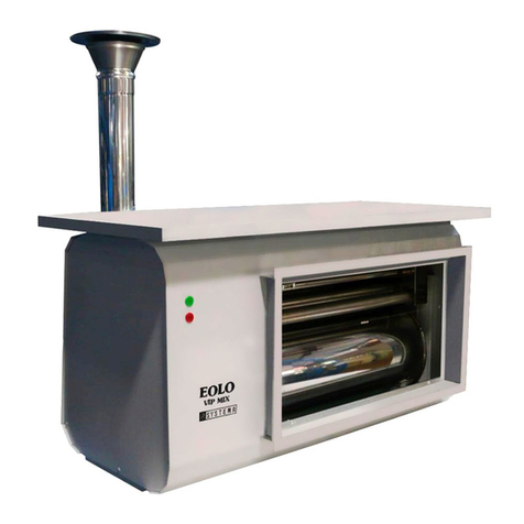
Systema KING User manual

01IT1810
ENGLISH
Instruction manual
“Installation, use and maintenance”
Rev. 14GBEN08062020
KING
AIRTIGHT GAS CONVECTORS
Pilot ame thermocouple series, natural balanced mod. KING 21
Ventilated/forced circulation series mod. KING 30 FE, KING 50 FE,
KING 70 FE
14GBEN08062020

2
SYSTEMA S.P.A. KING rev. 14GBEN08062020
Symbols used in the manual
ISO 9001: 2015
N.B.
It indicates information useful for consulting the manual and for ecient operation of the equipment.
IMPORTANT
It indicates important information and practical suggestions.
DANGER
In this manual the word DANGER combined with the symbol shown to the side indicates a danger with
a high level of risk which, if not avoided, will result in death or serious injury.
WARNING
In this manual, the word WARNING combined with the symbol shown to the side indicates a hazard with
a medium level of risk which, if not avoided, could result in death or serious injury.
ATTENTION
In this manual, the word ATTENTION combined with the symbol shown to the side indicates a hazard
with a low level of risk which, if not avoided, could result in minor or moderate injury.
READ CAREFULLY BEFORE USE.
KEEP FOR FUTURE REFERENCE
Before installation, check that the local conditions of distribution, the nature of the gas and
of the pressure are compatible with the setting of the appliance.
In order to improve the product, Systema reserves the right to modify its contents
as required and without warning.
Via Antonio Ceccon, 3
35010 LOREGGIA (PD) ITALIA
Tel. +39 049.935.5663
(8 lines)
Fax 0039 049.935.5699
E-mail: [email protected]
Technical information
http://www.systema.it
Sales information

3
I
SYSTEMA S.P.A. KING rev. 14GBEN08062020
SUMMARY
SUMMARY
1 GENERAL RULES.................................................................................................................................................... 5
1.1 TERMINOLOGY USED IN THE MANUAL.........................................................................................................................8
2 PACKAGING............................................................................................................................................................. 9
2.1 PACKING LIST ..................................................................................................................................................................9
2.2 STORAGE .........................................................................................................................................................................10
3 GENERAL TECHNICAL CHARACTERISTICS........................................................................................................ 11
3.1 IDENTIFICATION PLATE AND INFORMATION LABELS .................................................................................................11
3.2 INFORMATION LABELS ...................................................................................................................................................12
3.2 DEVICE CLASSIFICATION ...............................................................................................................................................13
3.3 DESCRIPTION AND OPERATIONAL CHARACTERISTICS.............................................................................................13
3.4 MAIN CONTROL AND SAFETY COMPONENTS .............................................................................................................13
3.5 TECHNICAL DATA.............................................................................................................................................................15
3.5.1 Informazioni obbligatorie secondo Regolamento (UE) 2015/1188 - DIRETTIVA 2009/125/CE........................................16
3.6 OVERALL DIMENSIONS KING 21, 30 FE, 50 FE.............................................................................................................17
3.7 OVERALL DIMENSIONS KING 70 FE ..............................................................................................................................18
3.8 EXPLODED VIEW KING 21 ..............................................................................................................................................19
3.9 EXPLODED VIEW KING 30 FE.........................................................................................................................................20
3.10 EXPLODED VIEW KING 50 FE.........................................................................................................................................21
3.11 EXPLODED VIEW KING 70 FE.........................................................................................................................................22
3.12 FLUE SYSTEMS ...............................................................................................................................................................23
3.12.1 Air/fume kit for King 21 ......................................................................................................................................................23
3.12.2 Air/fume kit for King 30 FE and King 50 FE.......................................................................................................................23
3.12.3 Air/fume kit for King 70 FE.................................................................................................................................................23
4 ELECTRIC DIAGRAM .............................................................................................................................................. 24
5 INSTRUCTIONS FOR INSTALLERS ....................................................................................................................... 26
5.1 PLACES OF INSTALLATION AND SAFETY DISTANCES................................................................................................26
5.2 INSTALLATION OF THE KING 21 AIR/FUME KIT ............................................................................................................27
5.3 INSTALLATION OF THE KING 30 FE-50 FE WITH STANDARD AIR/FUME KIT.............................................................28
5.4 INSTALLATION OF KING 30 FE-50 FE WITH "FLUSH WITH THE WALL" AIR/FUME KIT ...................................................................... 29
5.4.1 Installation of King with side wall exhaust pipe for KING 30 FE, KING 50 FE...................................................................30
5.5 MESSA IN OPERA KING 70 FE........................................................................................................................................32
5.6 GAS PIPING......................................................................................................................................................................34
5.6.1 PilotamegasvalveforKing21 .......................................................................................................................................35
5.6.2 Regulationofpilotamegasvalve....................................................................................................................................36
5.6.3 Solenoidgasvalve“ELECTRONIC”typeforKing30FE,King50FE,King70FE...........................................................37
5.7 ELECTRICAL CONNECTIONS .........................................................................................................................................37
5.8 STARTING AND OPERATION OF PILOT FLAME DEVICES KING 21.............................................................................38
5.9 STARTING AND OPERATION OF ELECTRONIC DEVICES KING 30 FE; KING 50 FE; KING 70 FE ............................38
5.10 USING THE DAILY PROGRAMMER (OPTIONAL)...........................................................................................................38
5.12 MALFUNCTIONS AND SOLUTIONS ................................................................................................................................39
5.12.1MalfunctionsandsolutionsforpilotamedevicesKing21 ...............................................................................................39
5.12.2MalfunctionsandsolutionsforelectronicdevicesKing30FE;King50FE.......................................................................39
5.12.3MalfunctionsandsolutionsforelectronicdevicesKing70FE...........................................................................................40
6 MAINTENANCE........................................................................................................................................................ 41
6.1 TRANSFORMATIONS FOR DIFFERENT SUPPLY TYPE OF GAS .................................................................................41
7 WARRANTY.............................................................................................................................................................. 42
7.1 OBJECT AND DURATION OF THE WARRANTY .............................................................................................................42
7.2 EXCLUSIONS FROM THE WARRANTY ..........................................................................................................................42
7.3 COMPETENCES...............................................................................................................................................................43
7.4 OPERATION AND EFFICIENCY OF THE WARRANTY....................................................................................................43

4
I
SYSTEMA S.P.A. KING rev. 14GBEN08062020
SUMMARY
7.5 RESPONSIBILITY .............................................................................................................................................................43
7.6 JUDICIAL DISPUTES - TERRITORIAL COMPETENCE AND POWERS OF THE PARTIES ...........................................43
8 STORAGE AND DISPOSAL..................................................................................................................................... 44
8.1 STORAGE .........................................................................................................................................................................44
8.2 DISPOSAL......................................................................................................................................................................... 44

5
1
SYSTEMA S.P.A. KING rev. 14GBEN08062020
GENERAL RULES
1 GENERAL RULES
These devices are designed and built according to EU Regulation 2016/426 (GAR).
■Read this manual before using this appliance.
■It is necessary to follow the instructions in this manual, particularly with regard to safety regulations.
■Systema declines all responsibility for direct or indirect damage to persons, animals or objects resulting from failure to
follow the instructions provided in this manual.
■This instruction manual is an integral and essential part of the appliance and must be stored carefully near the system
for further consultation.
■Carefully read the instructions and warnings contained in this manual before installation and use as they provide impor-
tant information regarding safety, installation, use and maintenance.
■In case of loss of this manual, contact the manufacturer immediately.
■In the event of a change of owner or a new renter, submit all the documentation relating to the heating system to the
new owner/renter.
■KING appliances are conceived for the heating of small rooms, exploiting the principle of forced convection, the device
can be used to heat delimited areas or complete rooms.
■When delivering the product, check the integrity and completeness of the product and of its components. If this product
and/or its elements demonstrate discrepancies, contact the agency that sold the appliance.
■At the end of the work, the installer will need to release to the owner the necessary documentation to certify that the
installation.
■was performed in a workmanlike manner and complies with the regulations in force in the country and in the place
where the product is installed.
■Temperatures that are too high in the heated space are harmful to health and are a waste of energy. Appropriate use
of the appliance is recommended.
■The manufacturer is responsible for the conformity of its product with the regulations in force when the product is mar-
keted.
■Compliance with current legislation and regulations for the design of the systems, installation, use and maintenance are
the sole responsibility for the relative competences of the designer, the installer and of the user.
■It is forbidden to distribute this product in the country where the appliance is installed without notifying the manufacturer
in advance. Specic documentation is required based on the country of destination of the product.
WARNING
■To ensure correct operation of the appliance it is essential to strictly follow the instructions given by the manu-
facturer, to use original accessories and spare parts and to arrange maintenance to be performed by qualied
personnel (at least once a year).
■Do not install the system at premises intended for craft or industrial activities where the processing items
and any materials in storage pose the risk of formation of gases, vapours or dusts that could generate res or
explosions.
■The rooms where the appliances are installed must have a permanent aeration surface in compliance with the regula-
tions in force.
■Entrust the installation, the construction of the gas piping, the electrical connection, initial ignition and maintenance to
professionally qualied personnel responsible in compliance with the current national and local legislation in force in the
country where the system is installed and as reported in this manual.
■Create the gas supply plant system and the electrical connections in compliance with the national and local regulations
in force in the country where the system is installed; moreover, where required, they must be designed by a qualied
professional.
■The systems (gas pipes, power supply, etc.) must be created without causing obstacles or risks to persons.
■Before starting the appliances, check that the data of the electric power supply and gas supply networks are compati-
ble with the indications provided in this manual and on the plates of the appliances. To ensure correct operation of the
appliance it is essential to strictly follow the instructions provided by the manufacturer and to arrange maintenance to
be performed by qualied personnel (at least once a year).
■This appliance must only be used for the use for which it was expressly intended. Any dierent use has to be considered
as improper and therefore dangerous.
■The manufacturer declines all civil and criminal liability in the event of any damage to persons or property resulting from
incorrect installation, adjustment and maintenance, modications and tampering, the use of non-original spare parts
and accessories, improper use and/or incorrect device, failure to comply with the instructions provided by the manufac-
turer and the intervention of unqualied personnel.

6
1
SYSTEMA S.P.A. KING rev. 14GBEN08062020
GENERAL RULES
■If the appliance is not used for lengthy periods of time, the following are recommended:
-set the main switch of the appliance and the general one of the system to "o"
-close the main gas shut-o valve.
■After lengthy periods of time when the appliance has not been used, it is advisable to contact the Technical Assistance
Service or technical personnel qualied for recommissioning.
■In case of stopping and/or malfunctioning of the system, deactivate it. Any repair or replacement of components must only
be carried out by qualied personnel using only original spare parts. Failure to comply with these rules could compromise
safety of the appliance. The user has free access only to the parts of the appliance whose operation do not require the
use of tools: the user is therefore not authorized to disassemble the casing of the appliance and carry out operations in
the inside. The user can only use the appliance with the casing assembled and xed.
■Do not leave the packaging elements (nylon, polystyrene foam, wood, staples, etc.) within the reach of children and/or
discarded as they are potential sources of danger and contamination. Collect and store them in a place designed for
this purpose.
Remember that the use of products that use electricity and gas entails the observance of certain fundamental rules such as:
■It is forbidden for unassisted disabled persons and children to use the product.
■If the installation room of the appliance is frequented by vulnerable people and / or children, provide special protections
to prevent contact with hot surfaces. However, these protections must not obstruct the passage of hot air and the thermal
radiation of the frontal section.
■It is forbidden to operate devices or electrical appliances such as: switches, electrical appliances, etc. where these is a
smell of gas. In similar cases, proceed as follows:
-open doors and windows to ventilate the premises;
-close the general gas shut-o valve;
-promptly intervene the professionally qualied personnel or the technical assistance service.
■It is forbidden to touch the appliance barefoot or with wet or damp parts of the body.
■All cleaning and maintenance operations are forbidden, with the appliance connected to the electric power supply. To
carry out these operations, rst turn the system main switch to "o" and close the fuel gas supply.
■It is strictly forbidden to tamper with or modify the safety or regulation systems without the authorisation and specic
indications of the manufacturer of the appliance.
■It is forbidden to pull, detach or twist the electrical cables exiting the appliance, even if it is disconnected from the power
supply.
■It is forbidden to open the appliance during its operation, rst set the main system switch to "o".
■It is forbidden to place objects on top of the appliance or to insert them through the exhaust pipes for combustion and
intake of combustion air products.
■It is forbidden to touch the exhaust pipe of the combustion products during operation of the product; contact during oper-
ation can result in burns because the pipe can reach high temperatures. Surfaces can remain at high temperatures even
after the appliance has been switched o. Switch o the system in the event of activities near the equipment and monitor
the control panel during the entire period of operation to prevent it from being switched on.
■Outdoor installation is prohibited.
■It is forbidden to operate on the controls of the equipment located on the control panel during maintenance activities. The
maintenance technician must place a warning sign on the control panel of the system for the duration of the maintenance
activities where the following phase is specied: "System under maintenance, IT IS FORBIDDEN to carry out opera-
tions on the control panel of the equipment.”
■It is forbidden to use the appliances as a support base and/or as a pedestrian surface.
■It is forbidden to cover the appliance with curtains, draperies, etc., In case of removable curtains, move them sideways
at a distance of 30 centimeters before turning on the appliance. In case of xed curtains, these must be 30 centimeters
away from the sides and upper edge of the appliance.
■Do not obstruct with rugs, hanging laundry, etc. the external air intake and ue gas exhaust terminal of the appliance.
■Do not lean the appliance against walls with combustible materials.
■It absolutely forbidden to place clothes, paper or various objects on the top of the appliance that may obstruct the pas-
sage of hot air coming out of the slots.
■It is forbidden to place containers with water on top of the appliance.
■It is forbidden to use the appliance to place wet clothes to dry.

7
1
SYSTEMA S.P.A. KING rev. 14GBEN08062020
GENERAL RULES
ATTENTION
Never leave clothes, paper or other objects that might obstruct the passage of hot air from the
slots on top of the radiator.
Delicate surfaces such as curtains, furniture, and wooden or plastic chairs must be kept at a
minimum distance of 30 cm from the device.
Provide extra protection against the risk of burning by contact of children, the elderly or dis-
abled with the hot surfaces of the shell wherever necessary. Such additional protection must
not obstruct the passage of hot air and the irradiation of heat from the front panel.
■King appliances must not be powered by fuel containing carbon monoxide or other toxic components.
■It is absolutely forbidden to ll the humidier cup with water (see pic. 3.7 and 3.8 pages 20-21) when it is in its position inside the
appliance. Remove the glass before lling it and be careful not to drop the water when putting it back into the appliance. Elec-
trocution alert, disconnect the power supply before carrying out the operation and ll the glass only up to 3-4 cm from the edge.

8
1
SYSTEMA S.P.A. KING rev. 14GBEN08062020
GENERAL RULES
1.1 TERMINOLOGY USED IN THE MANUAL
Air-tight gas radiators
An air heating product that transfers the heat from a generator directly to the air and incorporates or distributes that heat
in an air heating system.
GCV (unit of measurement MJ/m³)
Higher caloric value, the total quantity of heat emitted from a unit of dried fuel mass to intrinsic humidity, when it is sub-
jected to complete combustion in the presence of oxygen and the combustion products are returned to room tempera-
ture; this quantity comprises the condensation heat of the water vapour formed by combustion of the hydrogen contained
in the fuel.
NCV (unit of measurement MJ/m³)
Lower caloric value, the total amount of heat emitted by a unit of fuel mass containing a suitable level of moisture, when
it is subjected to complete combustion in the presence of oxygen and when the combustion products have not returned
to ambient temperature.
Heat output (unit of measurement kW)
It is the product of the lower caloric value (NCV) of the fuel used and of the burnt fuel ow rate.
Heating power (unit of measure kW)
It corresponds to the thermal capacity reduced from the heating output lost at the chimney.
Professionally qualied personnel
An individual with training, instruction and/or technical experience relevant to the subject which allows them to perceive
the risks and to avoid the dangers that arise during use of a product, in possession of the technical-professional require-
ments, if imposed by the current legislation.
Vulnerable person
People with reduced physical, sensory or mental abilities (e.g. partially disabled, adults with reduced physical and mental
abilities), or without experience and knowledge (e.g. older children).
Children
Young people including very young children (ages 0 to 36 months); young children (older than 36 months, but younger
than 8 years); older children (aged 8 to 14).
Risk
Combination of the probability of the occurrence of damage and its severity.
Danger
Potential source of damage.
Damage
Physical injury, or damage to the health of persons or the deterioration of property or of the environment.
Electrocution
Electric discharge to which the human body is subjected by an operator who comes into contact with a part under elec-
trical voltage.
User
An individual or organisation that uses the devices.

9
2
SYSTEMA S.P.A. KING rev. 14GBEN08062020
PACKAGING
2 PACKAGING
2.1 PACKING LIST
a. The appliance, complete with all its parts, is delivered packed in a cardboard box where you can nd the
screw kit for a proper installation on the wall.
b. In case of supply of several units, they are overlapped in 4 appliances.
c. The instruction manual is placed inside the packaging.
d. The air / ue gas terminals and the mask are delivered packed in a carton.
ATTENTION
Perform the unpacking operation with the aid of appropriate equipment and/or protections
according to current legislation, and use appropriate equipments.
GAS CONVECTORS FLUE GAS-AIR KIT
(See paragraph 3.11)
Fig. 2.1 Package contents

10
2
SYSTEMA S.P.A. KING rev. 14GBEN08062020
PACKAGING
2.2 STORAGE
Upon the arrival at the customer or distributor site, the appliance must be stored away from atmospheric
agents, in a dry place, specically dedicated for this purpose (ex. warehouse, shed).
The handling of the packaging must be carried out safely and with care, the manufacturer declines all respon-
sibility for damage to persons, animals or things, caused during the handling of the packaging.
The warranty on the products is void if they are stored in a place unsuitable for this purpose, or if it does not
comply with the instructions described above, in order to avoid that the elements of the product can be dam-
aged or cause malfunctions or problems once installed.
ATTENTION
The handling of the material must take place according to the procedures described in this
manual.
A single operator does not have to manually move loads greater than 25 kg, it is advisable
to carry out manual handling by two workers. In case of lifting of loads of less than 25 kg by
a single operator, it is advisable to bend the knees and apply strength on the legs: during
transport, keep the load close to the body while keeping the spine erect.
Fig. 2.2
Important
It is forbidden to stack the packages supplied by the manufacturer each other on the top.

11
3
XXXXXXXX XX/XXXX
XXXXXXXXXXX XXXXXXXXXXX
XXXXXXXXXXXXXXXX
XX XXX XXX,XXX,XXX,XXX
XX XXX XXX XXX XXX XXX
XXX
XXX
XXX
XXX
XXX
XXX
XXX
XXX
XXX
XXX
XXX
XXX
XXX
XXX
XXX
XXX
XXX
XXX
XXX
XXX
XXX
XXX
XXX
XXX
XXX
XXX
XXX
XXX
XXX
X/XX XXX/XX
X XXX
SYSTEMA S.P.A. KING rev. 14GBEN08062020
CHARACTERISTICS
3 GENERAL TECHNICAL CHARACTERISTICS
3.1 IDENTIFICATION PLATE AND INFORMATION LABELS
Inside the product is applied the product identication label showing all the identication data that distinguish
the equipment.
These indications include the unique serial number for each product. With this number the manufacturer can
precisely identify the model and all the technical data for the product in case of requests for assistance. A
warning label is located on the outside. All labels must be kept intact on the appliance and must be replaced
if they become illegible.
Useful life, according to a proper use and maintenance of the product recommended by the manufacturer: 20
years.
Important
the serial number of the product is essential
for adequate and fast service.
Important
The position of the product identication data-plate may change depending on the model (g.3.1)
Fig. 3.1
SYSTEMA S.p.A.
Via S. Martino 17/23
Santa Giustina in Colle (PD) - ITALY
Serial number Year XXXX
Model Destination
CategoryPIN Code
Heat output (Hi) Type
Heatingcapacity(Hi)
Supplypressure
Max burner pressure
Nozzle diameter
ElectricalPowerSupply Degree of protection
Electrical PowerNOx
Class
Regulated for XXXXXXXXXXXX
Max nominal consumption
Typesofgas

12
3
SYSTEMA S.P.A. KING rev. 14GBEN08062020
CHARACTERISTICS
Fig. 3.2
Fig. 3.3
3.2 INFORMATION LABELS
Sull’imballo del generatore sono applicate alcune etichette di informazioni (g. 3.2).
All’interno dell'imbalaggio, assieme al manuale di istruzioni, sono presenti le etichette da utilizzare per il cam-
bio di combustibile (g. 3.3).

13
3
SYSTEMA S.P.A. KING rev. 14GBEN08062020
CHARACTERISTICS
3.2 DEVICE CLASSIFICATION
For the classication we refer to the European standards EN 613: 2000 + A1: 2003 (balanced ow) and EN
1266: 2002 + A1: 2005 (forced ow).
Device type: C11 (King 21), C13 (King 30 FE e King 50 FE) and C12 (King 70 FE) depending on the ue gas
suction and expulsion system used. Device output class: 1
3.3 DESCRIPTION AND OPERATIONAL CHARACTERISTICS
The airtight gas convector radiator is composed of a combustion chamber for the combustion of a gaseous
component (methane or LPG) (entrust maintenance operations to a professional and qualied team in
compliance with the current national and local legislation in force in the country where the appliance
is installed, as reported in this manual), in airtight cast iron divided into two half-shells that can be opened
for cleaning and the inspection of the burner. The working temperature of the external surface of the combus-
tion chamber as fanned by the natural convection movement of the surrounding air or the forced circulation of
the fans is usually reached in a few minutes.
The functioning of the appliance is automatic. The device functions automatically, and is equipped with the
appropriate systems for safety, control, mixing, combustion, starting, the suction of combustion air and ue
gas expulsion.
The combustion air suction and ue gas expulsion systems must be mandatorily connected directly to the
building’s exterior (C-type devices) and therefore there is no contact between the combustion chamber and
the building’s interior. This guarantees the maximum safety and permits the installation of the device indoors
in complete respect of the standards in force.
3.4 MAIN CONTROL AND SAFETY COMPONENTS
a. Electric control unit for the Electronic series models: this can be of two types depending on the convector
model involved (forced or naturally balanced circulation). After receiving the electric signal from the room
thermostat, the control unit runs a normal check on the pressure-switch when forced convectors are being
controlled (if this check is not positive, the control unit does not grant triggering). The control unit then gives
the signal for the performance of the pre-starting lubrication of the combustion chamber (>4 lubrications) and
then the signal for spark ignition and starting by opening the gas solenoid valve. If no ame is detected (by
the ionization probe) within the established safety time, the device goes into lock-out. In order to reset after
lock-out, switch o the bipolar switch with the orange l.e.d. and then switch it back on again.
b. Pilot gas valve: there is only one type of pilot gas valve for all pilot ame convector models - a multifunctional
valve with single control and combined manual all-or-nothing thermostat control equipped with thermoelec-
tric ame detection device with reset inhibition, maximum owrate pre-selection device or pressure regula-
tor, minimum owrate pre-selection screw, all-or-nothing modulation thermostat, pilot ame output with gas
owrate pre-selection screw, inlet lter and pilot lter, inlet and outlet pressure taps - lateral gas outlets or
gas outlets from below with RP 3/8 ISO 7 threads. To start, press the dial and switch on the pilot ame by
keeping the dial pressed down for a few seconds. Then release the dial and check to make sure that the pilot
ame remains on. If the pilot ame has gone out in the meantime, the reset inhibition device will prevent the
re-starting of the convector until the established pilot ame detection device safety time has elapsed.
c. Gas solenoid valve: for all electronic series and forced ventilation convectors, multifunctional and multigas
with a double safety solenoid valve (connected in series) in Class A and a built-in rectier bridge. The alumi-
num body holds the inlet gas connections - threaded G 1/2" outlet with respective pressure taps. Equipped
with pressure regulator to be adjusted only by qualied technicians, the only maintenance operation possible
on the valve.
d. Air suction unit: this serves to suck the air from the outside and inject it into the combustion chamber with the
consequent expulsion of the ue gases outwards through the appropriate ue gas duct.
e. Adjustment thermostat: this is a sensor-type thermostat that permits the temperature to be adjusted as
required by the user for a comfortable room temperature, and also permits the control of the starting and
switching o of the device from the control unit.
f. Daily or weekly programmer (only on request): this serves to program the device’s daily and weekly opera-
tion cycles and is positioned on the control panel for access by the user for adjustment purposes.

14
3
SYSTEMA S.P.A. KING rev. 14GBEN08062020
CHARACTERISTICS
PILOT GAS VALVE TECHNICAL DATA: KING 21
Gas connections................................................................. RP 3/8 ISO 7
Max. inlet pressure ............................................................. 50 mbar
Pressure setting range ....................................................... 3 ÷ 18 mbar
Room temperature.............................................................. 0° ÷ 80°C
Pressure regulator.............................................................. CLASS C
Pilot ame detection device................................................ Sit series 200 or 290 thermocouple
Starting time ....................................................................... < 10 s
Switch o time .................................................................... < 60 s
SOLENOID GAS VALVE TECHNICAL DATA T 840 Sigma: KING 30 FE; KING 50 FE; KING 70 FE
Gas connections................................................................. RP 1/2 F ISO 7
Power supply voltage ......................................................... 230 VAC 50/60 Hz
Electrical protection rating .................................................. IP44
Closing time........................................................................ ≤ 1 s
Work temperature............................................................... 0°C ÷ +60°C (-20°C ÷ +60°C optional)
Humidity.............................................................................. 90% max - 40% non condensing
Max. inlet pressure ............................................................. 60 mbar
SUCTION UNIT MOTOR RATING DATA PLATE: KING 30 FE; KING 50 FE; KING 70 FE
Electrical power supply ...................................................... 230 VAC 50 Hz
Insulation ............................................................................ CLASS H
Motor pack.......................................................................... of 30 mm
Power ................................................................................. 20 WATT
ELECTRONIC THERMOSTAT: KING 30 FE; KING 50 FE; KING 70 FE
Power supply voltage ......................................................... 230 VAC -15% +10% 50Hz
Work range ......................................................................... 6°C ÷ 40°C
Temperature dierential...................................................... 0,5°C
Internal probe type.............................................................. NTC 4,7kΩ @ 14°C
Relative humidity ................................................................ 20% ÷ 80% RH (non condensing)
PRESSURE SWITCH SPECIFICATIONS KING 70 FE COD. 00CEPR1105
Mounting position ............................................................... Vertical
Max. work pressure ............................................................ 5000 Pa
Reset point (opening) ......................................................... 60 Pa (+ 12 Pa)
Pneumatic connection ........................................................ Ø 6,2 mm
Work temperature............................................................... -30°C ÷ +85°C
CONTROL UNIT TECHNICAL CHARACTERISTICS SIT 579-DBC: KING 30 FE; KING 50 FE; KING 70 FE
Power supply voltage ......................................................... 230 Vac 50/60Hz (-15% + 10%)
Work temperature............................................................... -20 ÷ 60°C
Pre-starting lubrication time................................................ 1...240 s
Starting safety time............................................................. max. 3...120 s
Switch-o safety time ......................................................... < 1 s
DATA PLATE TANGENTIAL FAN MOTOR - single-phase asynchronous
King model............................KING 30 FE.......................... KING 50 FE ..........................KING 70 FE
Type......................................TAS18B ................................ TAS36B.................................03B-3050/1Q
Power supply voltage ...........230V~50/60 Hz .................... 230V~50/60 Hz.....................230 V~50Hz
Electrical power ....................28 W..................................... 45 W .....................................35/110 W
Electrical absorption .............-............................................ -.............................................0,55 A
Capacitor ..............................-............................................ -.............................................2,5 μF 470V
Speed ...................................1500 RPM ............................ 1380 RPM.............................1100 RPM
Insulation type ......................H........................................... H...........................................B

15
3
SYSTEMA S.P.A. KING rev. 14GBEN08062020
CHARACTERISTICS
Balanced ow pilot
ame series models Forced ow electrononic series models
Models
NATURAL
CONVECTION FORCED FLOW AND VENTILATED
KING 21 KING 30 FE KING 50 FE KING 70 FE
Category II2H3B/P, II2H3P
Ratedheatow kW 2 3 4,9 7,2
Working heat output kW 1,75 2,73 4,37 6,62
Combustionefciency* % 87,3 91,0 89,1 92,0
Efciencyclass 1 1 1 1
Supplypressure
Nat. gas (G 20) mbar 20
LPG-Butane (G 30) mbar 30
LPG-Propane (G 31) mbar 30
Nozzle pressure
(valveregulatorexcludedforLPG)
Nat. gas (G 20) mbar 12,0 13,0 9,0 14,0
LPG-Butane (G 30) mbar -- -- -- --
LPG-Propane (G 31) mbar -- -- -- --
Burner nozzle diameter
Nat. gas (G 20) mm 1,25 1,50 2,10 2,20
LPG-Butane (G 30) mm 0,70 0,85 1,20 1,30
LPG-Propane (G 31) mm 0,75 0,90 1,25 1,35
Max fuel consumption
(15°C-1013 mbar)
Nat. gas (G 20) m3/h 0,212 0,317 0,519 0,762
LPG-Butane (G 30) kg/h 0,158 0,237 0,386 0,568
LPG-Propane (G 31) kg/h 0,155 0,233 0,381 0,559
Electricalpowersupply V/Hz -- 230/50
Electrical power (absorbed) W -- 71,5 71,5 129
Treatedambientairow m3/h -- 150 260 470
Heatedambientvolume m336 58 102 154
Fan speed number -- 2 2 2
Dimensions
Width mm 600 590 745 880
Height mm 624 616 616 710
Depth mm 225 225 225 330
Weight kg 31 33 52 44
Gas Fitting Diameter Pollici(“) 1/2”-M 1/2”-F 1/2”-F 1/2"-F
Air-fume coaxial pipe diameters Air mm 100 60 60 100
Fume mm 60 38 38 60
Air-fume max length (Coaxial pipes) mm 500 5000 3000 5000
Typeofequipment C11 C13 C13 C12
*Standardconditions
3.5 TECHNICAL DATA
Tab. 3.1 Technical data

16
3
SYSTEMA S.P.A. KING rev. 14GBEN08062020
CHARACTERISTICS
Model identication KING
21
KING
30 FE
KING 30 FE
(with timer)
KING
50 FE
KING 50 FE
(con timer)
KING
70 FE
KING 70 FE
(with timer)
Indirectheatingfunctionality no no no no no no no
Direct thermal power 1,75 kW 2,73 kW 2,73 kW 4,37 kW 4,37 kW 6,62 kW 6,62 kW
Indirect thermal power N.A. N.A. N.A. N.A. N.A. N.A. N.A.
Fuel (gaseous) Natural gas (G20)
Data Simbolo Unità Value Value Value Value Value Value Value
Emissions due to space heating - nitrogen oxides
(≤130mg/kWhinput)NOX
[mg/kWhinput]
(GCV) 118 126 126 87 87 128 128
Thermal power
Nominal thermal power Pnom kW 1,75 2,73 2,73 4,37 4,37 6,62 6,62
Minimum thermal power Pmin kW N.A. N.A. N.A. N.A. N.A. N.A. N.A.
Minimum thermal output (percentage of nominal
thermal output) .. % N.A. N.A. N.A. N.A. N.A. N.A. N.A.
Electrical auxiliary consumption
At nominal thermal power elmax kW N.A. 0,071 0,071 0,071 0,071 0,129 0,129
At minimum thermal power elmin kW N.A. N.A. N.A. N.A. N.A. N.A. N.A.
Instand-bymode elSB kW N.A. N.A. N.A. N.A. N.A. N.A. N.A.
Power required for permanent pilot ame
Requiredpowerforthepilotame(ifapplicable) Ppilot kW 0,25 N.A. N.A. N.A. N.A. N.A. N.A.
Useful efciency (GCV)
Usefulefciencyatnominalheatoutput ηth,nom % 87,3 91,0 91,0 89,1 89,1 92,0 92,0
Usefulefciencyatminimumheatoutput ηth,min % N.A. N.A. N.A. N.A. N.A. N.A. N.A.
Seasonal energy efciency of ambient heating
(≥72%) ηS% 72,2 78,5 80,5 79,0 81,0 81,1 83,1
Type of heat output / environment temperature control (indicate only one option)
singlephaseheatoutputwithoutenvironmenttemperaturecontrol no no no no no no no
twoormoremanualsphaseswithoutenvironmenttemperaturecontrol no no no no no no no
withenvironmentaltemperaturecontrolbymechanicalthermostat yes no no no no no no
withenvironmentaltemperaturecontrolbyelectronicthermostat no yes no yes no yes no
withenvironmentaltemperaturecontrolviaelectronicthermostatanddaily
timer no no yes no yes no yes
withenvironmentaltemperaturecontrolvia electronic thermostat andwe-
eklytimer no no no no no no no
Other control options (multiple options can be selected)
environmentaltemperaturecontrolwithpresencedetection no no no no no no no
environmentaltemperaturecontrolwithopenwindowdetection no no no no no no no
with remote control option no no no no no no no
with adaptable start control no no no no no no no
with operating time limitation no no no no no no no
with black globe thermometer no no no no no no no
ENERGY EFFICIENCY CLASS DCCCCCB
3.5.1 Informazioni obbligatorie secondo Regolamento (UE) 2015/1188 - DIRETTIVA 2009/125/
CE
Tab. 3.2 Regulatory Data (UE) 2015/1188

17
3
SYSTEMA S.P.A. KING rev. 14GBEN08062020
CHARACTERISTICS
3.6 OVERALL DIMENSIONS KING 21, 30 FE, 50 FE
Gas Connection 10 cm
min.
IMPORTANT: the KING gas convector must be installed at 10 cm minimum distance from the
ground; it is necessary to forsee the space for the gas interception. The hole for the gas pipe
has to be provided under the appliance, between the appliance and the ground, according to
the gas inlet of the appliance itself.
CONVECTOR OVERALL DIMENSIONS AND ASSEMBLY FRAME
MODELS A B C D E F G H I
KING 21 600 624 225 385 611 173 212 125 116
KING 30 FE 590 616 225 535 612 305 230 60 108
KING 50 FE 745 616 225 689 612 399 290 60 108
The data provided above are purely indicative. The Manufacturer reserves the right to perform modications
without notice.
Tab. 3.3
Fig. 3.4

18
3
SYSTEMA S.P.A. KING rev. 14GBEN08062020
CHARACTERISTICS
3.7 OVERALL DIMENSIONS KING 70 FE
ASSEMBLY FRAME (front view)
IMPORTANT: the KING gas convector must be installed at 10 cm minimum distance from the
ground; it is necessary to forsee the space for the gas interception. The hole for the gas pipe
has to be provided under the appliance, between the appliance and the ground, according to
the gas inlet of the appliance itself.
Tab. 3.4
Fig. 3.5
CONVECTOR OVERALL DIMENSIONS AND ASSEMBLY FRAME
MODELLI A B C D E F G H I L M N O P
KING 70 FE 880 710 330 835 710 20 397 25 678 7 170 232 Ø100 Ø8
The data provided above are purely indicative. The Manufacturer reserves the right to perform modications
without notice.

19
3
SYSTEMA S.P.A. KING rev. 14GBEN08062020
CHARACTERISTICS
3.8 EXPLODED VIEW KING 21
KING 21 PILOT FLAME TYPE THERMOCOUPLE SERIES CONVECTOR
Pos. Q.ty Description Code
1 1 Shell 02MACO0028
2 1 Door 02CNPO0304
3 1 Cast iron casting with burner Various
4 1 Eurositpilotamevalve 02CNVE0679
5 1 Air box 02CNSA0378
Tab. 3.5
Fig. 3.6 Exploded view mod. KING 21

20
3
SYSTEMA S.P.A. KING rev. 14GBEN08062020
CHARACTERISTICS
3.9 EXPLODED VIEW KING 30 FE
KING 30 FE VENTILATED/FORCED CIRCULATION SERIES
Pos. Q.ty Description Code Pos. Q.ty Description Code
1 1 Shell 02MACO0031 10 1 Copper pipe 02CNTU0494
2 2 Door 02CNPO0304 11 1Gasvalvesupport 02CNSU0741
3 1 Heat shield 02CNSE0503 12 1 Electrical control panel 02CEQU0343
4 1 Cast iron casting with burner Various 13 1 Thermostat 02CETR2805
5 1 Tangential fan 02CEVT0622 14 1 Dailytimerprogrammer(optional) 02CETM0475
6
1 Detection electrode 02CNER0625 15 1 Air box 02CNSA0376
1 Ignition electrode 02CNEA0624 16 1 Humidiercontainer 02CNCO2708
7 1 90° bend connection 02CNCU0138 17 1 Fan connection 02CNMA0238
8 1 Control unit 02CEAP2702 18 1 Centrifugal fan EV 100 02CEAS3002
9 1 Solenoidgasvalve 02CEEL0167
Tab. 3.6
Fig. 3.7 Exploded view mod. KING 30 FE
ATTENTION
It is absolutely forbidden to ll the glass (16) with water
when it is in its proper position inside the appliance. Re-
move the glass before lling it and be careful to avoid any
water drop when putting it back into the appliance. Elec-
trocution warning, disconnect the power supply before
carrying out the operation and ll the glass only up to 3-4
cm from the edge.
This manual suits for next models
4
Table of contents
Other Systema Heater manuals