41001379 Iss 01
ELECTRICAL CONNECTIONS
The heater is suitable for connection to a 415 volt 3 phase 50Hz
supply. .
On full heat setting the load is 9, 12 or 14kW depending of the
model.
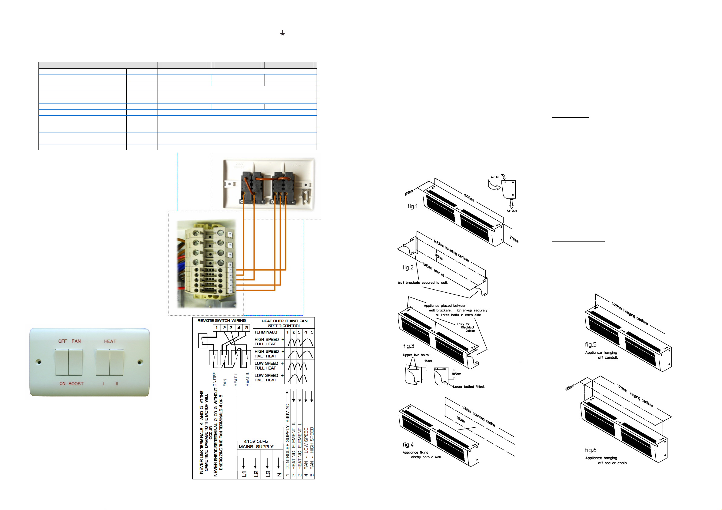
The connections between the unit and remote switch box are
shown on the rear of this instruction sheet, Fig 8.
FUSES
The motor and switch circuits are protected by two fuses
which have a 3 amp rating. Ensure that any replacement is of the
correct size and rating.
MAINTENANCE
ALWAYS ENSURE THAT THE MAIN EXTERNAL ELECTRICITY
SUPPLY IS SWITCHED OFF BEFORE SERVICING OF THIS
SCREEN-ZONE HEATER.
To obtain the best results from the heater it is essential to
avoid the accumulation of dust and dirt within the unit and on the
inlet and discharge grilles. Regular cleaning is necessary with
particular attention to the fronts and backs of the fan motor blades.
Cleaning of the fan is best carried out with a soft brush.
CONTROLS
The units are designed to provide 2 levels of heat ie half heat
and full heat, together with 2 fan speeds, normal and boost. The
remote control box houses 4 switches. The switch plate is marked
as shown below. The functions of the switches are as follows:-
SWITCH 1 (left-hand) ON/OFF
SWITCH 2 FAN SPEED CONTROL
SWITCH 3 ½ HEAT
SWITCH 3 + SWITCH 4 FULL HEAT
TO REPLACE A SWITCH IN THE CONTROL BOX
a) Switch off the mains supply
b) Remove the switch box cover.
c) Disconnect the wiring to the switch.
d) Release the spring clips and push out the switch.
e)
Fit the replacement switch, reconnect the wiring and replace
the cover.
For safety reasons a good earth connection must ALWAYS be made to the
unit and the control box. On the heater the earth terminal is adjacent to the
terminal block and is clearly marked with the symbol .
The unit should be wired in accordance with BS7671 latest edition
requirements for electrical installations. The installer should ensure that a suitable
fused isolating switch is connected in the mains supply.
THERMAL CUT-OUTS
There are 2 thermal cut-outs protecting the heater, positioned along
the heater box. These cut-outs are connected in series and each or both
may operate in the event of fan failure or restriction to the free flow of air
through the unit. The unit is protected by manual type cut-outs which
may only be reset by hand when the heater is switched OFF and has
cooled down. If the cut-outs trip, check the inlet and outlet grilles for
airflow restrictions.
TO RESET THE CUT-OUTS
a) The cut-outs are reset by switching OFF mains power to the
appliance and allowing the appliance to cool for 20 minutes.
b) Remove the appliance lid and locate the 2 cut-outs. Ensure mains
power is OFF. Reset each cut-out by pressing the white 5 mm
square reset button located on each cut-out.
c) Replace appliance lid. Switch ON the appliance. The cut-outs will
be reset. If the cut-outs trip again a qualified electrician should be
consulted.
SPARES
It is essential when ordering spares or replacement parts to state
the model number HSACW9000, HSACW12000 or HSACW14000 and
the serial number on the rating place fixed to the top of the unit.
In the interest of progress the Company reserves the right to vary
specifications from time to time without notice. The material listed is
offered subject to the Company’s General Conditions of Sale, a copy of
which can be obtained on request.
MOUNTING
When mounted over a doorway, the unit should be mounted as low
as possible and not more than 3.4 metres above the floor. A single unit
will give adequate coverage for a 1.2 metre doorway. For wider
doorways, units may be mounted end to end. The heater should be
mounted so that the inlet or outlet air flow are not obstructed in any way.
A clearance of at least 300 mm should be maintained around the inlet
and outlet grilles.
INSTALLATION
Having removed the appliance lid, to acquire these Instructions, also
ensure that the Remote Control Switch Box, which is packed inside the
appliance with these Instructions, is removed and retained.
The appliance ‘air flow’ and ‘external dimensions’ are shown in Fig 1.
The heater may be mounted in one of several ways ie:-
1. Wall Mounting
a. Using WALL BRACKETS supplied.
Onto a suitable vertical wall or bearers, the 2 wall brackets are
secured at the centres shown in Fig 2. The appliance, with 2 upper bolts
threaded securely into each face, is then fitted onto/between the wall
brackets as shown in Fig 3. The lower fixing bolts are then fitted through
each wall bracket into each side of the appliance.
The upper 2 bolts allow the appliance to be slipped onto, and held
by, the wall brackets. The fitting of the lower bolts in each side locks the
appliance to the brackets.
Tighten-up securely all 3 bolts in each side.
b. DIRECTLY to a suitable vertical wall or bearers.
Using 4 x No.12 wood screws. Screw through the holes in the
appliance case rear, at the centres shown in Fig 4. Keyhole slots are
provided for the upper 2 fixing screws, allowing the appliance to be
initially located. The lower 2 fixing screws pass through the appliance
rear, supporting the appliance and preventing any movement up off the
upper 2 screws.
The wall surface to which the appliance is to be mounted must be
flat to avoid any distortion of the appliance casing.
2. Suspended/Hanging
a. Using Ø20mm CONDUIT.
The appliance may be suspended by Ø20mm conduit via two
suitable holes provided in the top of the appliance, see Fig 5.
b. Studding.
The heater offers four M8 threaded holes as shown in Fig 6. from
which the appliance may be suspended.
Electrical Data HSACW9000 HSACW12000 HSACW14000
Supply voltage 415V three phase 50Hz
kW 9 12 14Total load
A/pha 12.6 16.7 19.6
Motor power W 60
Max Running current Amps 0.6
Internal fuse size amps Amps 3
External fuse size amps A/pha 16 20 25
Cable terminal size 10mm
2
Max
Mains terminal block position Centre of base unit.
Terminals N; L1; L2 & L3
Control terminal block cable size 4mm
2
Max
Control terminal block position Centre of base unit.
Terminals 1-5
Control terminal block current Amps 0.6


