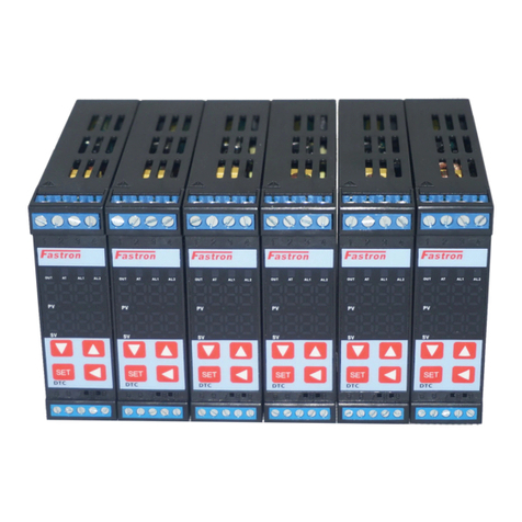
FASTRON. DTC1 Series User manual

DTC1Series
IntelligentTemperature/HumidityPID
Controllerwith60StepProgramControl
UserManualV1.0
ThankyouforpurchasingFastronDTCseriesPID
Temperature/HumidityController.Thismanualexplains
howtoinstallandoperateyournewPIDController.
Beforeoperation,pleasereadthismanualfirsttofully
understandtheoperationofthisproduct.Thiscontroller
shouldbeinstalledbyaqualifiedElectricalEngineer,
TechnicianorElectrician.Forspecifictechnicalsupport
pleasecontactyouragentorrepresentative.
SafetyWarning
1a)AvoidtouchingtheACpowerterminalsafterthecontrollerispowered
on.
1b)Alwaysensurethesupplypowerisofffirstbeforeconnectingany
wires.
1c)Donotoperatethisinstrumentinplacesfullofexplosiveand
combustiblegases.
2.IncorrectConnectionofthePowerSupplycancausepermanent
damage.
3.Themaximumtorqueoftheterminalsshouldnotexceed8KN.
4.Pleasedonotuseinthefollowingcircumstances:
●wherethetemperaturechangesdramatically
●Placeswherehumidityistoohigh(~85%)andwaterisproduced
●Wherevibrationorimpactishigh
●Wherecorrosivegasesordustarepresent
●splashofwater,oilandchemicals
6.AllWiringshouldbekeptawayfromhighvoltage,highcurrentpower
ImprovedFeatures
(1)Slopevalueoffsetcompensation.
(2)2in(input)2out(output):1to2isolatedtransmission,2to1isolatedtransmission
(Optional)
(3)Multiplealarmmodes
(4)TransmissionofPV,SVandMV:forward,reverseanddifferencevaluein8ways.
(5)Outputsoftstartfunction.
(6)Dehumidificationfunction.
(7)ServoMotorControl(Optional)
(8)Optional60Segment,MultiSequence,ProgramControl
ProgrammingMenu
WiringConfiguration
Forapplicationnotesandexamplespleasevisit
https://fastron.com.au/blogs/pidtemperaturecontrollers


1.SensorTypeSetting
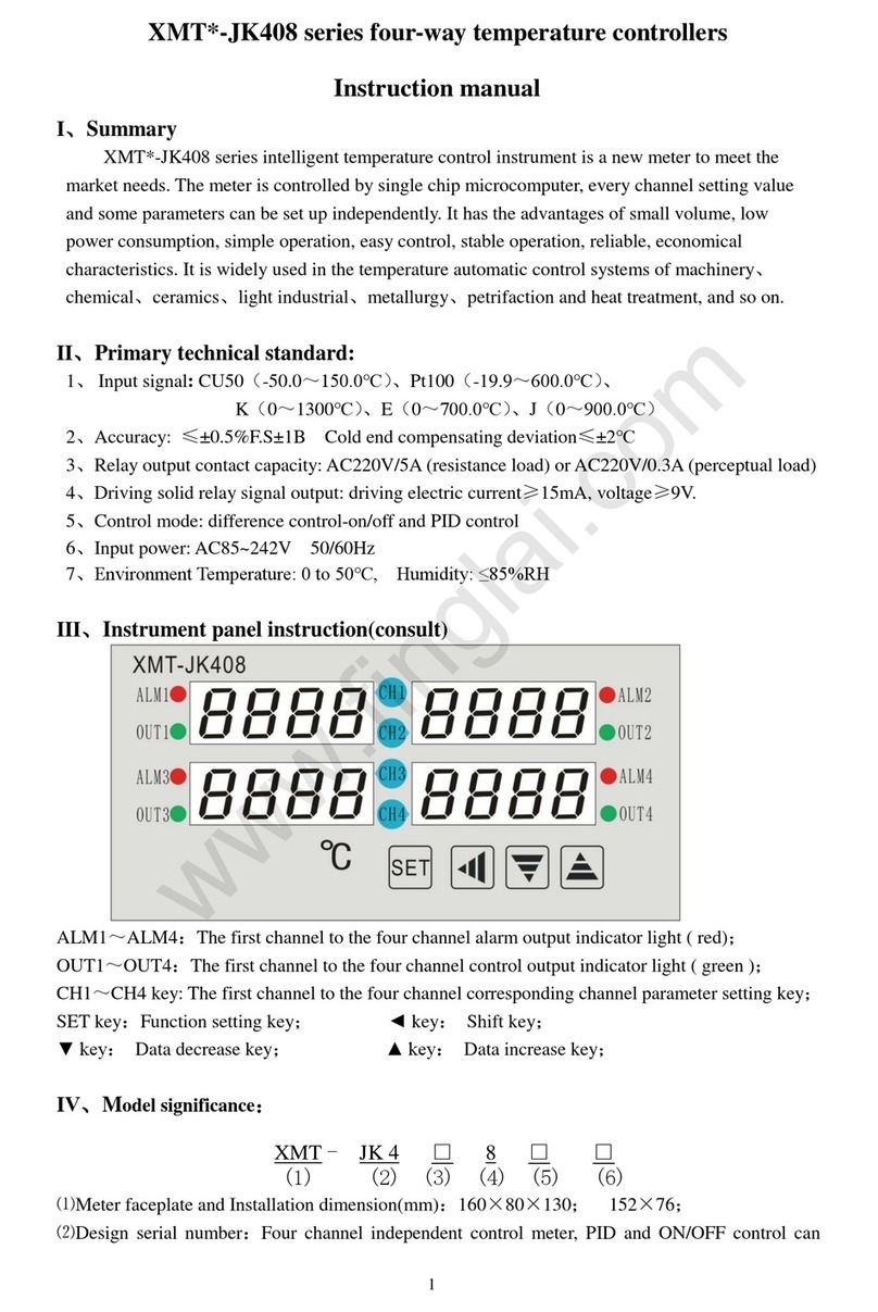
A.PressSET+◄keytoenterLEVEL3
B.OnceyoureachINPPress◄andtheSV
displaywillblink
C.Press▼or▲selecttheinputtype(refertothe
signalinputselectiontable).PressSETtoconfirm
E.Atthesametime,pressSET+◄toreturnto
LEVEL1
2.AL1/AL2Alarmmodesetting
A.PressSETfor5secondstoenterLEVEL2
B.PressSETseveraltimestoaccessAD1,thenpressthe
◄keyandthedisplaywillstarttoflash.
C.Press▼or▲selectthealarmtype(seealarmselection
table)
D.PressSETtoconfirm
E.PressSETtoreturntoLEVEL1
Step(3):SetalarmvalueAL1/AL2
SeeAL1andAL2inalarmmodeTable
A.PressSETkeyseveraltimestoaccessAL1
selection,andthenpress◄toenablethe
selection.
B.Press▲or▼toSETthevalue,andthenpress
the◄keytomovetothenextdigitanddoBoth
AL1andAL2canchoosealarmmodefrom0to10,
whichcanthesamesetting.
C.Aftersetting,pressSETkeytoconfirm.Pattern
EndoutputcanbeselectedasAlarmmode11.
Thereisalsoaconstanttemperatureandtiming
alarmmode19
D.PressSETtoreturntoLEVEL1settingandtest
thealarmfunctionorpatternendoutput.
Step(5):Autotuning(AT)Function
A.Onceinstalledinthefield,carryoutselftuningtoallow
thecontrollertodeterminetheoptimumATparameters.
B.ATcalculationwillchoosetheoptimumPIDParameters
basedonthecontrollersautotuningalgorithm.
C.Themaximumvalueoftheprocesscurveshouldbe
about80%oftherangeofinstrumentdetection.
D.Beforetheprogramisnotstarted(fixedvaluecontrol
STA=0),itisbettertocarryoutATaroundthemaximum
valueoftheprocesscurve(SV=0.3).E.InLEVEL1
process,pressSETkeyseveraltimestoreachAToption,
thenpressandkeytoput"1"tostartATcalculation.
F.ThismachineisusedasafixedvaluecontrolwhenSTA
="0",andasaprogramcontrollerwhenSTA=1,2,3.
G.Oncethecontrollerispoweredon,aslongasSTAdoes
notequal0(theprogramcontrolmachinedoesnotstartthe
programoperation,thecontrollerhasnooutput.
RateofChange/SlopeTemperatureLimit
Whenyoursystemneedsasoftstart(SVpresetslopeheating),pleaseoperateinthefollowingorder:
SETSVvalue→atLEVEL1,pressSETkeytofindRAPtoSETslopetemperaturevalue,and→thenpressSET
keytofindRTMtoSETslopetimeinminutes(forexample,SETslopeto10/min,RAPto10.0,RTMto001.0)
→aftersetting,SVvaluewillbeSETimmediatelyfromthecurrentPVvalueto10/min,untilreachingtheSET
SVvalue.
SlopeheatingprocessPROTheoutputpercentageofnormaltemperaturelightsflashingcontrolprocessis
automaticallycontrolledbyPID
SoftStartFunction
OutputSoftStart
ToenablesimplesoftstartfeaturesettheSVasfollows;
SetSVvalue>Inlevel3pressSETkeytoreachDLY,SETtheoutputsoftstartvalueinseconds(I.e.ifDLYis
setto10,thenthesoftstarttimewillbe10seconds).Exitthemenubypressingsetuntilyoureturntothemain
screen.Nowthesoftstartfunctionisactivatedwhenthecontrolissettobeginheating.

1.Scopeofselection:FastronElectronicsDTCSeriesfittedwithRS485
ModbusRTU“C5”Option
2.Workrealization:dataexchangebetweeninstrumentandhostcomputer
(instrumentcanonlybeusedasslavetoreceiveinterrogationandreply)
3.Serialtransmissionmode:RTU
4.Transmissioninterface:RS485
5.Communicationmedium:shieldedtwistedpair
6.Communicationstacknumber:1~255.Theupperlimitofthenumberof
connectingmetersisrelatedtotheloadcapacityofthehost,typicallyover15
or31metersrequiresignalIsolator/amplifier.
7.Functioncodeimplementation:readholdregister(03),writesingleregister
(06),writemultipleregisters(10)
8.Datalength:
8a)Whenwritingdatatothecontroller,amaximumof16consecutive
instructions(32bytes)canbewrittenatonetime.
8b)Whenreadingthemenudatainsidethemachine,thenonprogrammed
menucanread16consecutivemenusatatime(theunrealizedaddress
outsidetheparameteraddresstableis0),whiletheprogrammedmenucan
onlyread16consecutivemenusatatime
9.Numericalformat:signed16bitbinarycomplement;Thedatareadis10.0
timeslarger;Beforewritingthedata,enlargethedata10.0timesbefore
sendingit;Noticethetransition.
RS485MODBUSRTUcommunication
protocol
Baudrate:4800,9600,19200,38400,76800,
153600bps
Startposition:1
Databit:8
Checkbit:E(even),N(none)Stopbits:1,2
Framecheckmethod:(CRC16)
Messageformat:(N=2)
Troubleshooting
CommunicationApplicationNotes
1.ReadAMandAM1(coldcontrolmanual)menus,0represents
manualstate,1representsautomaticstate.
2.RAPistheprogramcontrolmenu,read,return0X0000
representstheprogramcontrolclose,return0X0001represents
theprogramcontrolstart:write0X0000toclosetheprogram
control,write0X0001tostarttheprogramcontrol,write0X0002
tostoptheprogramcontrol,write0X0002toendthe
suspension,continuetoruntheprogramcontrol.
3.Beforewritingtheprogramcontrolledmenu,pleasewrite
0x0000toRAPtoclosetheprogramcontrolledmenu.
4.BeforewritingMV/MV1threshold,pleasefirstwrite0x0000to
AM/AM1tomakethesystemswitchtomanualcontrol.
5.Whenthemultiplieris10,thereturneddataismagnified10
times.
6.PV1andPV2arereadonlyparameters.
7.Thereshouldbea150ms+timeintervalbetweenwrite
instructions,nomatterthesameaddressornotnot.instrument
failure,andthetimeintervalshouldbenolessthan150
milliseconds.
DTC1C5CommunicationsManual
This manual suits for next models
1
Table of contents
Other FASTRON. Temperature Controllers manuals

