YOKOGAWA UTAdvanced UT55A User manual

User’s
Manual UT55A/UT52A
Digital Indicating Controllers
User’s Manual
IM 05P01C31-01EN
IM 05P01C31-01EN
6th Edition

Product Registration
Thank you for purchasing YOKOGAWA products.
YOKOGAWA provides registered users with a variety of information and services.
Please allow us to serve you best by completing the product registration form accessible
from our homepage.
http://www.yokogawa.com/ns/reg/


i
IM 05P01C31-01EN
6th Edition : Jan. 2011 (YK)
All Rights Reserved, Copyright © 2009-2011 Yokogawa Electric Corporation
Introduction
Thank you for purchasing the UT55A/UT52A digital indicating controller (hereinafter
referred to as UT55A/UT52A).
This manual describes how to use UT55A/UT52A functions other than UT55A/UT52A’s
communication function and ladder sequence function. Please read through this user’s
manual carefully before using the product.
Note that the manuals for the UT55A/UT52A comprise the following seven documents:
● Printedmanual
ManualName ManualNumber Description
UT55A/UT52A Operation
Guide (for Standard model) IM 05P01C31-11EN
This manual describes the basic operation
method. It is also contained in the provided
CD-ROM.
UT55A/UT52A Operation
Guide (for Detailed model) IM 05P01C31-15EN
This manual describes the basic operation
method. It is also contained in the provided
CD-ROM.
● ElectronicmanualscontainedintheprovidedCD-ROM
ManualName ManualNumber Description
UT55A/UT52A Operation
Guide (for Standard model) IM 05P01C31-11EN This is identical to the printed manual.
UT55A/UT52A Operation
Guide (for Detailed model) IM 05P01C31-15EN This is identical to the printed manual.
UT55A/UT52A
User’s Manual IM 05P01C31-01EN
This manual. It describes the usage of all
functions except the ladder sequence and
communication functions.
UTAdvanced Series
Communication Interface
(RS-485, Ethernet)
User’s Manual
IM 05P07A01-01EN
This manual describes how to use
UT55A/UT52A in Ethernet and serial
communications. For communication wiring,
see the Operation Guide or User’s Manual.
UTAdvanced Series
Communication Interface
(Open Network)
User’s Manual
IM 05P07A01-02EN
This manual describes how to use UT55A
in PROFIBUS-DP/DeviceNet/CC-Link
communications. For communication wiring,
see the Operation Guide or User’s Manual.
LL50A Parameter Setting
Software Installation Manual IM 05P05A01-01EN This manual describes how to install and
uninstall the LL50A.
LL50A Parameter Setting
Software User’s Manual IM 05P05A01-02EN
This manual describes how to use the
LL50A, ladder sequence function, peer-to-
peer communication, and network profile
creating function.
* User’s Manual can be downloaded from a website.
Target Readers
This guide is intended for the following personnel;
● Engineersresponsibleforinstallation,wiring,andmaintenanceoftheequipment.
● Personnelresponsiblefornormaldailyoperationoftheequipment.
Notice
● Thecontentsofthismanualaresubjecttochangewithoutnoticeasaresultof
continuing improvements to the instrument’s performance and functions.
● Everyefforthasbeenmadetoensureaccuracyinthepreparationofthismanual.
Should any errors or omissions come to your attention, however, please inform
YokogawaElectric’ssalesofceorsalesrepresentative.
● Undernocircumstancesmaythecontentsofthismanual,inpartorinwhole,be
transcribed or copied without our permission.
ii IM 05P01C31-01EN
Trademarks
● Ourproductnamesorbrandnamesmentionedinthismanualarethetrademarksor
registered trademarks of Yokogawa Electric Corporation (hereinafter referred to as
YOKOGAWA).
● Microsoft,MS-DOS,Windows,WindowsXP,WindowsVista,andWindows7are
either registered trademarks or trademarks of Microsoft Corporation in the United
States and/or other countries.
● Adobe,Acrobat,andPostscriptareeitherregisteredtrademarksortrademarksof
Adobe Systems Incorporated.
● EthernetisaregisteredtrademarkofXEROXCorporationintheUnitedStates.
● ModbusisaregisteredtrademarkofSchneiderElectric.
● PROFIBUS-DPisaregisteredtrademarkofPROFIBUSUserOrganization.
● DeviceNetisaregisteredtrademarkofOpenDeviceNetVenderAssociation,Inc.
● CC-LinkisaregisteredtrademarkofCC-LinkPartnerAssociation(CLPA.)
● WedonotusetheTMor®marktoindicatethesetrademarksorregistered
trademarks in this user’s manual.
● Allotherproductnamesmentionedinthisuser’smanualaretrademarksorregistered
trademarks of their respective companies.
Safety Precautions
This instrument is a product of Installation Category II of IEC/EN/CSA/UL61010-1 Safety
Standards and Class A of EN61326-1, EN55011 (EMC Standards).
CAUTION
This instrument is an EMC class A product. In a domestic environment, this product
may cause radio interference in which case the user needs to take adequate
measures.
The instrument is a product rated Measurement Category I (CAT.I).
* Measurement Category I (CAT.I)
This category applies to electric equipment that measures a circuit connected to a
low-voltage facility and receives power from stationary equipment such as electric
switchboards.
To use the instrument properly and safely, observe the safety precautions described in
this user’s manual when operating it. Use of the instrument in a manner not prescribed
herein may compromise protection features inherent in the device. We assume no liability
for or warranty on a fault caused by users’ failure to observe these instructions.
This instrument is designed to be used within the scope of Measurement Category I (CAT.
I) and is dedicated for indoor use.
NotesontheUser’sManual
• This user’s manual should be readily accessible to the end users so it can be referred
to easily. It should be kept in a safe place.
• Read the information contained in this manual thoroughly before operating the
product.
• The purpose of this user’s manual is not to warrant that the product is well suited to
any particular purpose, but rather to describe the functional details of the product.

iii
IM 05P01C31-01EN
Safety,Protection,andModificationoftheProduct
The following symbols are used in the product and user’s manuals to indicate safety
precautions:
AC
AC/DC
“Handle with Care” (This symbol is attached to the part(s) of the product to
indicate that the user’s manual should be referred to in order to protect the
operator and the instrument from harm.)
The equipment wholly protected by double insulation or reinforced insulation.
Functional grounding terminal (Do not use this terminal as a protective grounding terminal.)
• In order to protect the system controlled by this product and the product itself, and
to ensure safe operation, observe the safety precautions described in this user’s
manual. Use of the instrument in a manner not prescribed herein may compromise the
product’s functions and the protection features inherent in the device. We assume no
liability for safety, or responsibility for the product’s quality, performance or functionality
should users fail to observe these instructions when operating the product.
•Installation of protection and/or safety circuits with respect to a lightning protector;
protective equipment for the system controlled by the product and the product itself;
foolproof or failsafe design of a process or line using the system controlled by the
product or the product itself; and/or the design and installation of other protective and
safety circuits are to be appropriately implemented as the customer deems necessary.
•
Be sure to use the spare parts approved by YOKOGAWA when replacing parts or consumables.
• This product is not designed or manufactured to be used in critical applications that
directly affect or threaten human lives. Such applications include nuclear power
equipment, devices using radioactivity, railway facilities, aviation equipment, air
navigation facilities, aviation facilities, and medical equipment. If so used, it is the
user’s responsibility to include in the system additional equipment and devices that
ensure personnel safety.
• Modicationoftheproductisstrictlyprohibited.
• This product is intended to be handled by skilled/trained personnel for electric devices.
• ThisproductisULRecognizedComponent.InordertocomplywithULstandards,
end-products are necessary to be designed by those who have knowledge of the
requirements.
WARNING
● PowerSupply
Ensure that the instrument’s supply voltage matches the voltage of the power
supply before turning ON the power.
● DoNotUseinanExplosiveAtmosphere
Do not operate the instrument in locations with combustible or explosive gases
orsteam.Operationinsuchenvironmentsconstitutesanextremesafetyhazard.
Use of the instrument in environments with high concentrations of corrosive gas
(H2S, SOX, etc.) for extended periods of time may cause a failure.
● DoNotRemoveInternalUnit
The internal unit should not be removed by anyone other than YOKOGAWA’s
service personnel. There are dangerous high voltage parts inside. Additionally,
do not replace the fuse by yourself.
● DamagetotheProtectiveConstruction
Operation of the instrument in a manner not specified in this user’s manual may
damage its protective construction.

iv IM 05P01C31-01EN
WarningandDisclaimer
• YOKOGAWA makes no warranties regarding the product except those stated in the
WARRANTY that is provided separately.
• The product is provided on an “as is” basis. YOKOGAWA assumes no liability to any
person or entity for any loss or damage, direct or indirect, arising from the use of the
product or from any unpredictable defect of the product.
Notes on Software
• YOKOGAWA makes no warranties, either expressed or implied, with respect to the
software’smerchantabilityorsuitabilityforanyparticularpurpose,exceptasspecied
in the terms of the separately provided warranty.
• Thissoftwaremaybeusedononespecicmachineonly.
• To use the software on another machine, the software must be purchased again
separately.
• It is strictly prohibited to reproduce the product except for backup purposes.
• Store the software CD-ROM (the original medium) in a safe place.
•All reverse-engineering operations, such as reverse compilation or the reverse
assembly of the product are strictly prohibited.
• No part of the product’s software may be transferred, converted, or sublet for use by
any third party, without prior written consent from YOKOGAWA.
HandlingPrecautionsfortheMainUnit
• The instrument comprises many plastic components. To clean it, wipe it with a soft,
drycloth.Donotuseorganicsolventssuchasbenzeneorthinnerforcleaning,as
discoloration or deformation may result.
• Keepelectricallychargedobjectsawayfromthesignalterminals.Notdoingsomay
cause the instrument to fail.
• Do not apply volatile chemicals to the display area, operation keys, etc. Do not leave
theinstrumentincontactwithrubberorPVCproductsforextendedperiods.Doingso
may result in failure.
• If the equipment emits smoke or abnormal smells or makes unusual noises, turn OFF
the instrument’s power immediately and unplug the device. In such an event, contact
your sales representative.
WasteElectricalandElectronicEquipment(WEEE),Directive2002/96/EC
This is an explanation of how to dispose of this product based on Waste Electrical and
Electronic Equipment (WEEE), Directive 2002/96/EC. This directive is only valid in the
EU.
Marking
This product complies with the WEEE Directive (2002/96/EC) marking requirement.
This marking indicates that you must not discard this electrical/electronic product in
domestic household waste.
Product Category
With reference to the equipment types in the WEEE directive Annex 1, this product is
classified as a “Monitoring and Control instrumentation” product.
Do not dispose in domestic household waste. When disposing products in the EU,
contactyourlocalYokogawaEuropeB.V.office.

v
IM 05P01C31-01EN
CheckingtheContentsofthePackage
Unpack the box and check the contents before using the product. If the product is
different from that which you have ordered, if any parts or accessories are missing, or if
the product appears to be damaged, contact your sales representative.
UT55A/UT52A Main Unit
The UT55A/UT52A main units have nameplates affixed to the side of the case.
Check the model and suffix codes inscribed on the nameplate to confirm that the product
received is that which was ordered.
No.(Instrumentnumber)
When contacting your sales representative, inform them of this number, too.
Note
The last digit of the display code (-x0) has been changed into the case color code.

vi IM 05P01C31-01EN
ModelandSuffixCodesofUT55A(forStandardmodel)
[Style:S4]
Model Suffix code
Optional
suffix
code
Description
UT55A DigitalIndicatingController(providedwithretransmissionoutputor15VDC
looppowersupply,3DIs,and3DOs)(Powersupply:100-240VAC)
Type 1:
Basic
control
-0 Standard type
-1 Position proportional type
-2 Heating/cooling type
Type 2:
Functions (*1)
0None
1Remote (1 additional aux. analog) input, 6 additional DIs, 5 additional DOs,
and RS-485 communication (Max.19.2 kbps, 2-wire/4-wire) (*2)
2Remote (1 additional aux. analog) input, 1 additional DI, and RS-485
communication (Max.19.2 kpbs, 2-wire/4-wire) (*2)
35 additional DIs and 5 additional DOs
4Remote (1 additional aux. analog) input and 1 additional DI
5Remote (1 additional aux. analog) input, 6 additional DIs, and 5 additional
DOs
65 additional DIs and 15 additional DOs
73 additional aux. analog inputs and 3 additional DIs
Type 3:
Open networks
0None
1RS-485 communication (Max.38.4 kbps, 2-wire/4-wire)
2Ethernet communication (with serial gateway function)
3CC-Link communication (with Modbus master function)
4PROFIBUS-DP communication (with Modbus master function)
5DeviceNet communication (with Modbus master function)
Display language (*3)
-1 English
-2 German
-3 French
-4 Spanish
Case color 0White (Light gray)
1Black (Light charcoal gray)
Fixed code -00 Always "-00"
Optional suffix codes
/DR Additional direct input (TC and 3-wire/4-wire RTD) and current input to
Remote (1 additional aux. analog) input, 1 DI to be deleted (*4)
/LP 24VDClooppowersupply(*5)
/HA Heater break alarm (*6)
/DC Powersupply24VAC/DC
/CT Coating (*7)
*1: When “1” or “6” is specified for the Type 2 code, only “0” can be specified for the Type 3
code.
*2: When the /LP option is specified, the RS-485 communication for “1” or “2” of the Type 2
code is 2-wire system.
*3: English, German, French, and Spanish can be displayed as the guide display.
*4: When any of “1,” “2,” “4,” “5,” or “7” is specified for the Type 2 code, the /DR option can be
specified.
*5: The /LP option can be specified in the combination of Type 2 code (any of "0," "2," "3," or
"4") and Type 3 code (any of "0" or "1"). Additionally, the /LP option can be specified in the
combination of Type 2 code "1" and Type 3 code "0."
*6: When “-0” is specified for the Type 1 code, the /HA option can be specified.
*7: When the /CT option is specified, the UT55A does not conform to the safety standards (UL
and CSA) and CE marking.

vii
IM 05P01C31-01EN
ModelandSuffixCodesofUT52A(forStandardmodel)
[Style:S4]
Model Suffix code
Optional
suffix
code
Description
UT52A DigitalIndicatingController(providedwithretransmissionoutputor15VDC
looppowersupply,3DIs,and3DOs)(Powersupply:100-240VAC)
Type 1:
Basic
control
-0 Standard type
-1 Position proportional type
-2 Heating/cooling type
Type 2:
Functions
0None
1Remote (1 additional aux. analog) input, 1 additional DI, and RS-485
communication (Max. 38.4 kbps, 2-wire)
2Remote (1 additional aux. analog) input and 1 additional DI
32 additional DIs and 2 additional DOs
Type 3:
Open networks 0None
Display language (*1)
-1 English
-2 German
-3 French
-4 Spanish
Case color 0White (Light gray)
1Black (Light charcoal gray)
Fixed code -00 Always "-00"
Optional suffix codes
/DR Additional direct input (TC and 3-wire/4-wire RTD) and current input to
Remote (1 additional aux. analog) input, 1 DI to be deleted (*2)
/LP 24VDClooppowersupply(*3)
/HA Heater break alarm (*4)
/DC Powersupply24VAC/DC
/CT Coating (*5)
*1: English, German, French, and Spanish can be displayed as the guide display.
*2: When “2” is specified for the Type 2 code, the /DR option can be specified.
*3: The /LP option can be specified in the combination of Type 1 code (any of "-0" or "-1") and
Type 2 code "0."
*4: When “-0” is specified for the Type 1 code, the /HA option can be specified.
*5: When the /CT option is specified, the UT52A does not conform to the safety standards (UL
and CSA) and CE marking.

viii IM 05P01C31-01EN
ModelandSuffixCodesofUT55A(forDetailedmodel)
[Style:S4]
Model Suffix code
Optional
suffix
code
Description
UT55A Digital Indicating Controller (provided with 3 DIs, and 3 DOs) (Power
supply:100-240VAC)
Fixed code -NNN Always "-NNN”
Display language (*1)
-1 English
-2 German
-3 French
-4 Spanish
Case color 0White (Light gray)
1Black (Light charcoal gray)
Output 1 (*2) (*3)
-A Analog output (current/voltage pulse)
-R Relay output (c-contact)
-U Universal output (current/voltage pulse/relay)
-T Triac output
-P Position proportional output
Output 2 (*2) (*3)
AAnalog output (current/voltage pulse)
RRelay output (c-contact)
UUniversal output (current/voltage pulse/relay)
TTriac output
NNone
Retransmission output /RT Retransmissionoutputor15VDCpowersupply
Heater break alarm (*3) /HA Heater break alarm
E1 terminal area (*4)
/R1 Remote (1 additional aux. analog) input and 1 additional DI
/U1 1additionaluniversalinput(TC/RTD/DCV/mA)
/X1 5 additional DIs
/Y1 5 additional DOs
/W1 2 additional DIs and 2 additional DOs
E2 terminal area (*4)
/A2 1 additional aux. analog input and 1 additional DI
/X2 5 additional DIs
/Y2 5 additional DOs
/W2 2 additional DIs and 2 additional DOs
E3 terminal area (*4) (*5)
/CH3 RS485 communication (Max. 38.4 kbps, 2-wire/4-wire)
/CC3 CC-Link communication
/PD3 PROFIBUS-DP communication
/DN3 DeviceNet communication
/ET3 Ethernet communication (with serial gateway function)
/X3 5 additional DIs
/Y3 5 additional DOs
/W3 2 additional DIs and 2 additional DOs
E4 terminal area (*4) (*5)
/A4 1 additional aux. analog input and 1 additional DI
/C4 RS485 communication (Max. 19.2 kbps, 2-wire/4-wire)
/L4 24VDClooppowersupply
/AC4 1 additional aux. analog input, 1 additional DI, and RS485 communication
(Max.19.2 kbps, 2-wire)
/LC4 24VDClooppowersupplyandRS485communication(Max.19.2kbps,
2-wire)
/X4 5 additional DIs
/Y4 5 additional DOs
/W4 2 additional DIs and 2 additional DOs
Power supply /DC Powersupply24VAC/DC
Additional treatment (*6) /CT Coating
*1: English, German, French, and Spanish can be displayed as the guide display.
*2: For heating/cooling output, both Output 1 and Output 2 should be specified. Not available when Output 2 is “N.” For
position proportional output, specify “-P” for Output 1 and “N” for Output 2.
*3: The /HA option can be specified only when the code for Output 1 and 2 is “-AN”, “-RN”, “-UN” or “-TN.”
*4: Only one option is available for each terminal area of E1 to E4.
*5: The /L4 and /LC4 options for E4 terminal area can be specified only when the E3 terminal area option is not specified
orspecifiedanyof/CH3,/X3,/Y3or/W3.
*6: When the /CT option is specified, the UT55A does not conform to the safety standards (UL and CSA) and CE marking.

ix
IM 05P01C31-01EN
ModelandSuffixCodesofUT52A(forDetailedmodel)
[Style:S4]
Model Suffix code
Optional
suffix
code
Description
UT52A Digital Indicating Controller (provided with 3 DIs, and 3 DOs) (Power supply:
100-240VAC)
Fixed code -NNN Always "-NNN”
Display language (*1)
-1 English
-2 German
-3 French
-4 Spanish
Case color 0White (Lithg gray)
1Black (Light charcoal gray)
Output 1 (*2) (*3) (*4)
-A Analog output (current/voltage pulse)
-R Relay output (c-contact)
-U Universal output (current/voltage pulse/relay)
-T Triac output
-P Position proportional output
Output 2 (*2) (*3) (*4) (*5)
AAnalog output (current/voltage pulse)
RRelay output (a-contact)
UUniversal output (current/voltage pulse/relay)
NNone
Retransmission output /RT Retransmissionoutputor15VDCpowersupply
Heater break alarm (*3) /HA Heater break alarm
E1 terminal area (*5) (*6)
/R1 Remote (1 additional aux. analog) input and 1 additional DI
/U1 1additionaluniversalinput(TC/RTD/DCV/mA)
/L1 24VDClooppowersupply
/CH1 RS485 communication (Max. 38.4 kbps, 2-wire/4-wire)
/RCH1 Remote (1 additional aux. analog) input, 1 additional DI, and RS485
communication (Max.38.4 kbps, 2-wire)
/LCH1 24VDClooppowersupplyandRS485communication(Max.38.4kbps,2-wire)
/X1 5 additional DIs
/Y1 5 additional DOs
/W1 2 additional DIs and 2 additional DOs
Power supply /DC Powersupply24VAC/DC
Additional treatment (*7) /CT Coating
*1: English, German, French, and Spanish can be displayed as the guide display.
*2: For heating/cooling output, both Output 1 and Output 2 should be specified. Not available when Output 2 is “N.” For
position proportional output, specify “-P” for Output 1 and “N” for Output 2.
*3: The /HA option can be specified only when the code for Output 1 and 2 is “-AN”, “-RN”, “-UN” or “-TN.”
*4: When the code for Output 1 is "-R" or "-U" and Output 2 is "R" or "U", Output 1 is changed from the contact point c to
the contact point a. When the code for Output 1 is specified to "-T", only "A" or "N" is available for Output 2.
*5: The /L1 or /LCH option can be specified only when the code for Output 2 is “N.”
*6: Only one option is available for E1 terminal area.
*7: When the /CT option is specified, the UT52A does not conform to the safety standards (UL and CSA) and CE marking.
CoatingTreatment
(1)HumiSeal coating treatment
Apply HumiSeal coating to the printed circuit board assembly.
Do not apply HumiSeal coating to the following parts: connector, gold-plated contact
area, relay part, RJC device, and in the vicinity of the push switch/LED lamp.
(2)Apply terminal coating to the gold-plated contact area on the printed circuit board.
Notes
▪Therearetwotreatmentsasdescribedabove,butwedonotguaranteetheir
effectiveness.
We do not supply any test data on these treatments.
▪Donotapplyanytreatmenttothescrewterminalareaonthebacksideofthe
instrument.

xIM 05P01C31-01EN
Accessories
The product is provided with the following accessories according to the model and suffix
codes. Check that none of them are missing or damaged.
For UT55A For UT52A
1 2
3
5
6
4
No. ProductName Quantity Remark
1 Brackets 2 Part number: L4502TP (For fixing the upper
and lower parts)
2 Terminal cover 1 ForUT55A:L4502XP
ForUT52A:L4502XQ
3 Unit label 1 Partnumber:L4502VZ
4Tag label 1 Partnumber:L4502VE(Onlywhenordered.)
5 Operation Guide 1 Single-loopcontrol(A3size,x6)(Standard
model only)
6 User’s Manual (CD-ROM) 1 Contains all manuals (Standard model only)

xi
IM 05P01C31-01EN
Accessory(soldseparately)
The following lists an accessory sold separately.
• LL50A Parameter Setting Software
Model Suffix code Description
LL50A -00 Parameter Setting Software
• Terminal cover
For UT55A, Model: UTAP001
For UT52A, Model: UTAP002
For UT55A For UT52A
• Brackets
Part number L4502TP (2 pieces for fixing the upper and lower parts)
•User’sManual(A4size)
* User’s Manual can be downloaded from a website.
• User’s Manual (CD-ROM), Model: UTAP003
* Contains all manuals.

xii IM 05P01C31-01EN
SymbolsUsedinThisManual
Thissymbolisusedontheinstrument.Itindicatesthepossibilityofinjurytotheuseror
damage to the instrument, and signifies that the user must refer to the user’s manual for
special instructions. The same symbol is used in the user’s manual on pages that the
user needs to refer to, together with the term “WARNING” or “CAUTION.”
WARNING
Callsattentiontoactionsorconditionsthatcouldcauseseriousorfatalinjurytotheuser,
and indicates precautions that should be taken to prevent such occurrences.
CAUTION
Callsattentiontoactionsorconditionsthatcouldcauseinjurytotheuserordamageto
the instrument or property and indicates precautions that should be taken to prevent such
occurrences.
Note
Identifies important information required to operate the instrument.
Indicates related operations or explanations for the user’s reference.
[ ]
Indicates a character string displayed on the display.
Setting Display
Indicates a setting display and describes the keystrokes required to display the relevant
setting display.
Setting Details
Provides the descriptions of settings.
Description
Describes restrictions etc. regarding a relevant operation.
HowtoOpenanElectronicManual
The provided CD-ROM contains PDF files of the manuals. Place this CD-ROM in the
PC’s CD-ROM drive; the Startup Window appears. Click on the relevant manual name to
open the selected manual.
If the Startup Window does not appear, select My Computer and double click on
UT_manual to open the manual concerned in the English directory.

xiii
IM 05P01C31-01EN
HowtoUseThisManual
For the ladder sequence and communication functions, see the respective manuals. This
user’smanualisorganizedintoChapters1to19asshownbelow.Thismanualmainly
uses the illustrations of the UT55A for describing the operations and functions. The basic
operations are the same for the UT52A, so please read them in the same way.
Chapter Title and Description
1Introduction to Functions
Describes the main functions of the UT55A/UT52A.
2UT55A/UT52AOperatingProcedures
Describes the flow from unpacking to regular operations.
3PartNames
Describes part names and functions on the front panel.
4BasicOperation
Describes basic operation of the UT55A/UT52A.
5QuickSettingFunction
Describes the minimum necessary settings for operation.
6MonitoringandControlofRegularOperations
Describes monitoring displays of regular operations and operation.
7Input(PV,Remote,andAuxiliaryAnalog)Functions
DescribesPVinput,remoteinput,andadvancedsecondarycontrolinput.
8Control Functions
Describes basic control and advanced control.
9Auxiliary Control Functions
Describes auxiliary control functions
10 Output(ControlandRetransmission)Functions
Describes output functions.
11 AlarmFunctions
Describes alarm output and status output.
12 ContactInput/OutputFunctions
Describes contact input/output functions.
13 Display, Key, and Security Functions
Describes display, user function key and security functions.
14 ParameterInitialization
Describestheinitializationtofactorydefaultvaluesandtouserdefaultvalues.
15
PowerFailureRecoveryProcessing/PowerFrequencySetting/OtherSettings
Describes operations performed after momentary power interruption and power
failures.
16 Troubleshooting,Maintenance,andInspections
Describes troubleshooting, maintenance, periodic inspections, and disposal.
17 Installation and Wiring
Describes installation and wiring.
18 Parameters
Provides parameter maps.
19 Specifications
Provides the UT55A/UT52A specifications.

Blank Page

xv
IM 05P01C31-01EN
1
2
3
4
5
6
7
8
9
10
11
12
13
14
15
16
17
18
19
App
Index
Contents
Introduction............................................................................................................................i
Target Readers......................................................................................................................i
Notice ................................................................................................................................i
Trademarks .......................................................................................................................... ii
Safety Precautions ............................................................................................................... ii
Handling Precautions for the Main Unit...............................................................................iv
Waste Electrical and Electronic Equipment (WEEE), Directive 2002/96/EC....................... iv
Checking the Contents of the Package ................................................................................v
Model and Suffix Codes of UT55A (for Standard model) .................................................... vi
Model and Suffix Codes of UT52A (for Standard model) ................................................... vii
Model and Suffix Codes of UT55A (for Detailed model).................................................... viii
Model and Suffix Codes of UT52A (for Detailed model)...................................................... ix
Symbols Used in This Manual............................................................................................ xii
How to Use This Manual ................................................................................................... xiii
Chapter1IntroductiontoFunctions
1.1 QuickSettingFunction ..................................................................................................... 1-1
1.2 Input/Output Function....................................................................................................... 1-2
1.3 Control Functions ............................................................................................................. 1-4
1.4 Display and Key Functions............................................................................................... 1-8
1.5 Ladder Sequence Function .............................................................................................. 1-9
1.6 Communication Functions.............................................................................................. 1-10
1.7 Definition of Main Symbols and Terms ........................................................................... 1-14
Chapter2UT55A/UT52AOperatingProcedures
2.1 UT55A/UT52A Operating Procedures .............................................................................. 2-1
Chapter3PartNames
3.1 Names and Functions of Display Parts ............................................................................ 3-1
3.2 Names and Functions of Keys ......................................................................................... 3-4
3.3 List of Display Symbols .................................................................................................... 3-7
3.4 Brief Description of Setting Details (Parameters)............................................................. 3-9
Chapter4BasicOperation
4.1 Overview of Display Switch and Operation Keys ............................................................. 4-1
4.2 How to Set Parameters .................................................................................................... 4-4
Chapter5QuickSettingFunction
5.1 SettingUsingQuickSettingFunction.............................................................................. 5-1
5.2 RestartingQuickSettingFunction.................................................................................... 5-6
Chapter6MonitoringandControlofRegularOperations
6.1 Monitoring and Control of Operation Displays.................................................................. 6-1
6.1.1 Operation Display Transitions in Single-loop Control, Cascade Primary-loop
Control, Cascade Secondary-loop Control, Loop Control for Backup, and Loop
ControlwithPV-holdFunction. ........................................................................... 6-1
Standard Type .....................................................................................................................6-1
Position Proportional Type...................................................................................................6-2
Heating/cooling Type ...........................................................................................................6-3
Single-loop Two-position two-level control...........................................................................6-4

xvi IM 05P01C31-01EN
6.1.2 OperationDisplayTransitionsinLoopControlwithPVSwitchingandLoop
ControlwithPVAuto-selector ............................................................................. 6-5
Standard Type .....................................................................................................................6-5
Position Proportional Type...................................................................................................6-6
Heating/cooling Type ...........................................................................................................6-7
6.1.3 Operation Display Transitions in Cascade Control ............................................. 6-8
Standard Type .....................................................................................................................6-8
Position Proportional Type.................................................................................................6-10
Heating/cooling Type .........................................................................................................6-12
6.2 Setting Target Setpoint ................................................................................................... 6-19
Operation in the Operation Display....................................................................................6-19
Operation in Parameter Setting Display ............................................................................6-20
6.3 Performing and Canceling Auto-tuning........................................................................... 6-21
6.4 AdjustingPIDManually .................................................................................................. 6-24
6.5 Setting Alarm Setpoint.................................................................................................... 6-30
6.6 Selecting Target Setpoint Number (SPNO) .................................................................... 6-31
6.7 Switching Operation Modes ........................................................................................... 6-32
6.7.1 Switching between AUTO and MAN ................................................................. 6-32
Direct Operation by A/M Key .............................................................................................6-32
6.7.2 Switching between CAS (Cascade), AUTO, and MAN ..................................... 6-34
6.7.3 Switching between STOP and RUN ................................................................. 6-36
6.7.4 Switching between REM (Remote) and LCL (Local) ........................................ 6-38
6.8 Manipulating Control Output during Manual Operation .................................................. 6-40
6.9 Releasing On-State (Latch) of Alarm Output.................................................................. 6-41
Chapter7Input(PV,Remote,andAuxiliaryAnalog)Functions
7.1 SettingFunctionsofPVInput,RemoteInput,andAuxiliaryAnalogInput........................ 7-1
7.1.1 Setting Input Type, Unit, Range, Scale, and Decimal Point Position.................. 7-1
7.1.2 Setting Burnout Detection for Input..................................................................... 7-5
7.1.3 Setting Reference Junction Compensation (RJC) or External Reference Junction
Compensation (ERJC)........................................................................................ 7-6
7.1.4 CorrectingInputValue ........................................................................................ 7-7
(1) Setting Bias and Filter ....................................................................................................7-7
(2) Setting Square Root Extraction and Low Signal Cutoff Point.........................................7-9
(3)Setting10-segmentLinearizer......................................................................................7-10
7.1.5 Setting Ratio bias/filter...................................................................................... 7-12
7.2 Setting Input Sampling Period (Control Period) ............................................................. 7-13
7.3 Using4-wireRTDasPVInput........................................................................................ 7-14
7.4 UsingLarger,Smaller,Average,orDifferenceofTwotoFourInputsasPV................. 7-15
7.5 Setting Remote Input Method......................................................................................... 7-16
7.6 AdjustingPVRangeforLoopControlwithPVSwitchingorLoopControlwithPVAuto-
selector........................................................................................................................... 7-17
7.7 SettingPVSwitchingMethodsofLoopControlwithPVSwitching................................ 7-18
Chapter8ControlFunctions
8.1 Setting Control Mode (CTLM) .......................................................................................... 8-1
8.1.1 Single-loop Control, Single-loop Heating/cooling Control, Single-loop Position
Proportional Control, and Single-loop Two-position Two-level Control ............... 8-1
nSingle-loop Control Function Block Diagram ...................................................................8-2
nSingle-loop Heating/cooling Control Function Block Diagram .........................................8-4
nSingle-loop Position Proportional Control Function Block Diagram .................................8-6
nSingle-loop Two-position Two-level Control Function Block Diagram ..............................8-8
8.1.2 Cascade Primary-loop Control...........................................................................8-11
nCascade Primary-loop Control Function Block Diagram................................................8-12
Contents

xvii
IM 05P01C31-01EN
1
2
3
4
5
6
7
8
9
10
11
12
13
14
15
16
17
18
19
App
Index
8.1.3 Cascade Secondary-loop Control, Cascade Secondary-loop Heating/cooling
Control, and Cascade Secondary-loop Position Proportional Control .............. 8-15
nCascade Secondary-loop Control Function Block Diagram...........................................8-17
nCascade Secondary-loop Heating/cooling Control Function Block Diagram .................8-18
nCascade Secondary-loop Position Proportional Control Function Block Diagram.........8-21
8.1.4 Cascade Control, Cascade Heating/cooling Control, and Cascade Position
Proportional Control.......................................................................................... 8-23
nCascade Control Function Block Diagram .....................................................................8-24
nCascade Heating/cooling Control Function Block Diagram ...........................................8-27
nCascade Position Proportional Control Function Block Diagram...................................8-29
8.1.5 Loop Control for Backup, Heating/cooling Loop Control for Backup, and
Position Proportional Loop Control for Backup................................................. 8-31
nLoop Control for Backup Function Block Diagram .........................................................8-33
nHeating/cooling Loop Control for Backup Function Block Diagram ...............................8-35
nPosition Proportional Loop Control for Backup Function Block Diagram.......................8-37
8.1.6
LoopControlwithPVSwitching,Heating/coolingLoopControlwithPVSwitching,
andPositionProportionalLoopControlwithPVSwitching
.................................. 8-39
nLoopControlwithPVSwitchingFunctionBlockDiagram..............................................8-40
nHeating/coolingLoopControlwithPVSwitchingFunctionBlockDiagram....................8-43
nPositionProportionalLoopControlwithPVSwitchingFunctionBlockDiagram ...........8-45
8.1.7
LoopControlwithPVAuto-selector,Heating/coolingLoopControlwithPV
Auto-selector,andPositionProportionalLoopControlwithPVAuto-selector
.... 8-47
nLoopControlwithPVAuto-selector(2inputs)FunctionBlockDiagram ........................8-49
n
Heating/coolingLoopControlwithPVAuto-selector(2inputs)FunctionBlockDiagram
....8-51
n
PositionProportionalLoopControlwithPVAuto-selector(2inputs)FunctionBlockDiagram
...8-52
n
LoopControlwithPVAuto-selector(4inputs)FunctionBlockDiagram(onlyforUT55A)
....8-55
n
Heating/coolingLoopControlwithPVAuto-selector(4inputs)FunctionBlockDiagram
(only for UT55A)
............................................................................................................8-57
nPositionProportionalLoopControlwithPVAuto-selector(4inputs)FunctionBlock
Diagram (only for UT55A).............................................................................................8-59
8.1.8 LoopControlwithPV-holdFunction,Heating/coolingLoopControlwithPV-hold
Function,andPositionProportionalLoopControlwithPV-holdFunction ....... 8-61
nLoopControlwithPV-holdFunctionFunctionBlockDiagram .......................................8-63
nHeating/coolingLoopControlwithPV-holdFunctionFunctionBlockDiagram..............8-64
nPositionProportionalLoopControlwithPV-holdFunctionFunctionBlockDiagram .....8-66
8.2 Setting Control Type (CNT) ............................................................................................ 8-68
8.2.1 PID Control ....................................................................................................... 8-69
8.2.2 ON/OFF Control (1 point of hysteresis / 2 points of hysteresis) ....................... 8-70
8.2.3 Heating/cooling Control .................................................................................... 8-72
8.2.4 Two-position Two-level Control......................................................................... 8-78
8.2.5 PD Control (Stable Control in Which a Setpoint is not Exceeded) ................... 8-80
8.2.6 Sample PI Control (Controlling a Process with Long Dead Time) .................... 8-81
8.2.7 Batch PID Control (Performing Control with Rapidly Settling Setpoints) .......... 8-83
8.2.8 Feedforward Control ......................................................................................... 8-85
8.3 Setting PID Control Mode (ALG) .................................................................................... 8-87
8.4 Switching PID ................................................................................................................. 8-89
8.4.1 Switching PID According to Target Setpoint Number (SPNO) .......................... 8-89
8.4.2 SwitchingPIDAccordingtoPV......................................................................... 8-90
8.4.3 Switching PID According to SP......................................................................... 8-92
8.4.4 Switching PID According to Target SP.............................................................. 8-94
8.4.5 Switching PID According to Deviation (Reference Deviation)........................... 8-96
8.4.6 Setting Hysteresis at Time of PID Switch ......................................................... 8-97
8.4.7 Switching PID by Contact Input ........................................................................ 8-97
8.5 Suppressing Overshoot (Super Function) ...................................................................... 8-98
Contents
This manual suits for next models
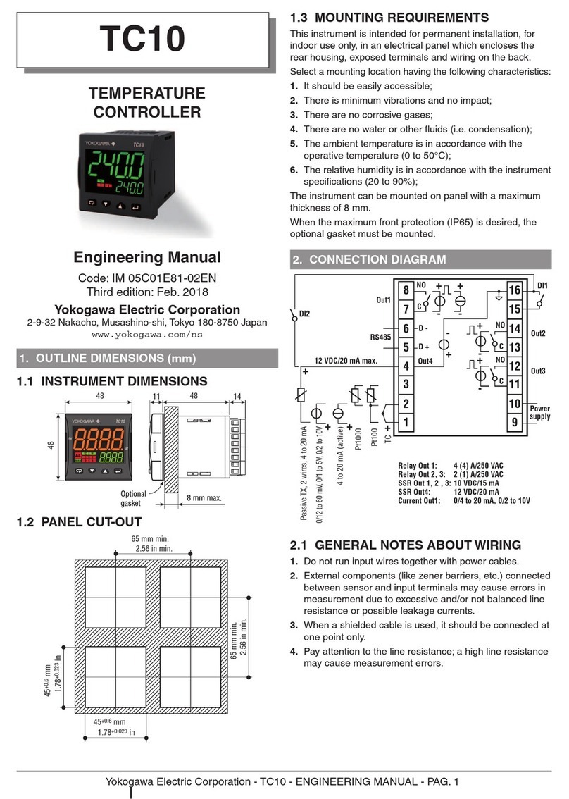
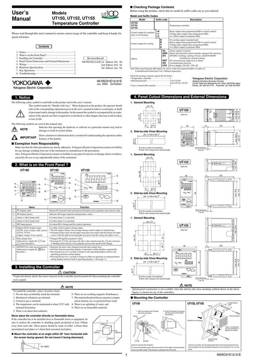
1
Table of contents
Other YOKOGAWA Temperature Controllers manuals

YOKOGAWA
YOKOGAWA XS550 User manual

YOKOGAWA
YOKOGAWA UP150 User manual

YOKOGAWA
YOKOGAWA TC User manual

YOKOGAWA
YOKOGAWA UT150 User manual

YOKOGAWA
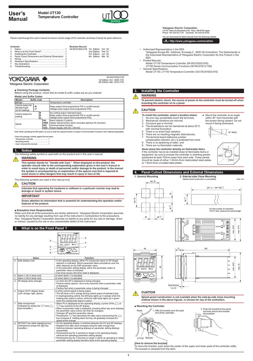
YOKOGAWA UT130 Manual

YOKOGAWA
YOKOGAWA Green Series User manual

YOKOGAWA
YOKOGAWA UP150 User manual

YOKOGAWA
YOKOGAWA TC10 User manual

YOKOGAWA
YOKOGAWA TC10 Installation and operation manual

YOKOGAWA
YOKOGAWA UT130 User manual