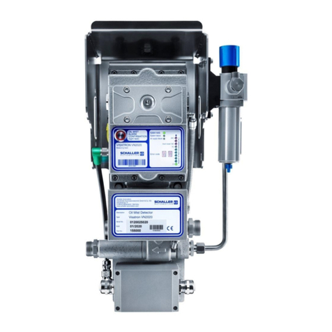
Schaller Automation VN115/87plus EX User manual

Operation Manual
Part-No. 180081
Version 1.3, 06/2016
VISATRON®
Oil Mist Detectors
VN115/87plus EX
IACS UR M67 type approved

Operation Manual VISATRON® VN115/87plus EX 06/2016
Page 2
SCHALLER AUTOMATION D-66440 Blieskastel / Saarland / Germany / Industriering 14 / P.O Box 1280
Industrielle Automationstechnik GmbH & Co. KG Tel. +49(0)6842-508-0/ Fax -260 / eMail: info@schaller.de / www.schaller.de
About this Manual
This operation manual was designed to answer your questions concerning the
handling, operation and maintenance of the Oil Mist Detector (OMD) VISATRON®
VN115/87plus EX. It contains no details about repairs.
The operating instructions are applicable for:
VN115/87plus EX
Should you encounter any interruption or breakdown of your VISATRON® OMD
device during operation, please contact your local representative (refer to chapter
10 ‘Service Partners’) or Schaller Automation, Industrielle Automationstechnik
GmbH & Co. KG directly. The repair of OMD devices should be carried out by
Schaller Automation directly. You can expect safe and reliable operation of your
OMD only when the device is operated in accordance with this manual.
Please take note of the following:
Please read this manual thoroughly and acquaint yourself with the correct
installation, operation and maintenance of your VISATRON® VN115/87plus EX
device.
Installations of the VISATRON® VN115/87plus EX devices have to be in
accordance to the IACS UR M10 if applicable.
Use the VISATRON® VN115/87plus EX devices only for the purpose described in
the operation manual.
Incorrect maintenance and handling errors may cause possible device failure or
an unsafe operating environment.
The VISATRON® VN115/87plus EX devices may only be used by authorised
staff.
This operation manual must be available at the place of installation at all times.
Terms and conditions of sale
The standard terms and conditions of sale of SCHALLER AUTOMATION shall apply to
all VISATRON® and related products.
SCHALLER AUTOMATION Industrielle Automationstechnik GmbH & Co. KG warrants
that under proper use, handling and maintenance OMD VISATRON® VN115/87plus
EX is free from defects in material, design and/or workmanship. Claims of
buyers/operators, in particular compensation for damage, which does not arise at
OMD VISATRON® VN115/87plus EX itself or for natural wear and tear of
consumable supplies, e.g. filters etc., are excluded. SCHALLER AUTOMATION
Industrielle Automationstechnik GmbH & Co. KG is not responsible for defects,
which arise as a result of:
a) natural wear and tear, improper commissioning, improper use/handling, use of
unsuitable power supply, welding processes on the engine as well as non-
observance of commissioning, installation, operating and service instructions as
given in this Operation Manual
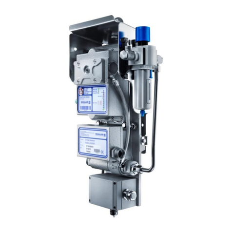
Operation Manual VISATRON® VN115/87plus EX 06/2016
Page 3
SCHALLER AUTOMATION D-66440 Blieskastel / Saarland / Germany / Industriering 14 / P.O Box 1280
Industrielle Automationstechnik GmbH & Co. KG Tel. +49(0)6842-508-0/ Fax -260 / eMail: info@schaller.de / www.schaller.de
b) components and design other than the OMD VISATRON® VN115/87plus EX
c) alterations or modifications of the OMD VISATRON® VN115/87plus EX carried
out by the buyer/operator or third parties without written authorization of
SCHALLER AUTOMATION Industrielle Automationstechnik GmbH & Co. KG
d) incorrect combination of devices and/or components or operation of devices
and/or components which are not certified to be compatible or not permitted by
the manufacturer - SCHALLER AUTOMATION Industrielle Automationstechnik
GmbH & Co. KG

Operation Manual VISATRON® VN115/87plus EX 06/2016
Page 4
SCHALLER AUTOMATION D-66440 Blieskastel / Saarland / Germany / Industriering 14 / P.O Box 1280
Industrielle Automationstechnik GmbH & Co. KG Tel. +49(0)6842-508-0/ Fax -260 / eMail: info@schaller.de / www.schaller.de
Safety instructions
The VN115/87plus EX devices are manufactured according to the high quality
standards of SCHALLER AUTOMATION and must pass stringent factory tests. In
order to keep the device in a smooth and problem free operation, the user has to
take note of the safety hints and warnings. In the instruction manual they are
marked with the following symbols.
Used symbols
CAUTION! Do not ignore the text in this box. Personnel
safety can be endangered or the device can be damaged.
WARNING! The marked text contains important information.
The marked text contains only a hint for faster processing.
EX-Symbol contains important interactions about Explosion
proof. CAUTION! Personnel safety can be endangered!
CAUTION! Unplug the OMD during welding processes
on the engine.
Reset of Oil Mist Alarms
CAUTION!
Use a monitoring device at a safe location (e.g. ECR)
to check for the actual oil mist concentration that is
requested by the IACS. In case of an Oil Mist Alarm,
Schaller Automation strongly recommends to
approach the engine only after indicated oil mist
concentration (LED chain) has lowered to half of its
bar indication (VISATRON®-device and Remote
Indicator II).
Follow the instructions of engine builder, ship yard
and ship owner!
In case of a High Oil Mist Alarm the Detector can be
reset if the Oil Mist Concentration has lowered below
the Alarm level.

Operation Manual VISATRON® VN115/87plus EX 06/2016
Page 5
SCHALLER AUTOMATION D-66440 Blieskastel / Saarland / Germany / Industriering 14 / P.O Box 1280
Industrielle Automationstechnik GmbH & Co. KG Tel. +49(0)6842-508-0/ Fax -260 / eMail: info@schaller.de / www.schaller.de
Advice for secure operation in potentially explosive atmospheres
Intended purpose
Operation in internal potentially explosive atmospheres
corresponding classification II-/2G (group II, category 2G,
operating resource for gas atmosphere). The requirements
of EN60079-0:2012+A11:2013 and EN60079-28:2007 are
met)
Labelling:
II (2G) [Ex op is IIB T4 Gb]
Permissible ambient temperature (during intended purpose):
Ta: +5°C ≤ Ta ≤ +70°C
Typical gasses of the ignition protection T4:
T4 maximum surface temperature <=135°C
Methane, acetone, ammonia, methanol, propane, toluol,
acetic acid, city gas, hydrogen, ethanol, n-butane, ethylene,
acetylene, automotive gas, diesel, heating oil, hydrogen
sulphide, acetaldehyde, diethyl ether.
Do always connect the OMD’s exhaust tube back to the
engine’s crankcase. The correct suction pressure in the
measuring head should be of 60mmWC!
In order to ensure the correct function of the OMD, the
pressure inside the engine’s crankcase shall be limited to
+/-500mmWC!
If the pressure is higher (or lower), Schaller Automation has
to be contacted!
Warning! The OMD has not to be cleaned with a steam
cleaner, high-pressure cleaner or solvent!
Warning! Do not interchange components of VN115/87plus
(non-EX) with VN115/87plusEX. Especially the detector’s
baseplate shall be of type VN115/87plusEX.
Important: The device is not intended to be mounted in an
EX area, it is designed to extract gases from a potentially
explosive atmosphere (e.g. the crankcase of a gas engine).

Operation Manual VISATRON® VN115/87plus EX 06/2016
Page 6
SCHALLER AUTOMATION D-66440 Blieskastel / Saarland / Germany / Industriering 14 / P.O Box 1280
Industrielle Automationstechnik GmbH & Co. KG Tel. +49(0)6842-508-0/ Fax -260 / eMail: info@schaller.de / www.schaller.de
VN115/87plus EX type label
Only expert staff is allowed to mount, connect and put into operation the
devices. The staff must have knowledge of the ignition protection,
instructions and prescriptions of the operating resources in EX-area.
Check, if the classification (see above “labelling” and labeling on the
device) is practical for this case of operation!
VN115/87plus EX type label explanation

Operation Manual VISATRON® VN115/87plus EX 06/2016
Page 7
SCHALLER AUTOMATION D-66440 Blieskastel / Saarland / Germany / Industriering 14 / P.O Box 1280
Industrielle Automationstechnik GmbH & Co. KG Tel. +49(0)6842-508-0/ Fax -260 / eMail: info@schaller.de / www.schaller.de
EC Declaration of Conformity
We, the manufacturer
SCHALLER AUTOMATION
Industrielle Automationstechnik GmbH & Co. KG
Industriering 14
D-66440 Blieskastel
Germany
Tel.: 06842 / 508-0
Fax: 06842 / 508-260
declare on our own responsibility, that the product:
Kind of equipment: Oil Mist Detector
Type-designation: VISATRON® VN115/87plus EX
Marking: 0637 || (2G) [EX op is llB T4 Gb]
to which this declaration relates exclusively used for the detection and signalizing of oil mist
in diesel aggregates and complies with the following EU-directives
Machinery directive 2006/42/EC
EMC directive 2004/108/EC
ATEX Equipment Directive 2014/34/EU
is in compliance with following standards:
EN ISO 4414: 2010
EN 60529: 1991+ A1: 2000+ A3: 2013
EN 55022: 2010
EN 61000-part 6-1: 2007, EN 61000-part 6-2: 2005, EN 61000-part 6-3: 2007+
A1:2011, EN 61000-part 6-4: 2007+ A1:2011
EN ISO 12100: 2010
EN 60079-0: 2012+ A11:2013
EN 60079-28: 2007
CSPRI 16-1
CSPRI 16-2
IACS UR M10: Rev.4 2013
IACS UR M67: Rev.2 2015
A technical documentation is completely available. The operating manual
according to the oil mist detectors is available in the original version.
D-66440 Blieskastel, 2016/06/15
Stephan Schaller
- Managing Director -

Operation Manual VISATRON® VN115/87plus EX 06/2016
Page 8
SCHALLER AUTOMATION D-66440 Blieskastel / Saarland / Germany / Industriering 14 / P.O Box 1280
Industrielle Automationstechnik GmbH & Co. KG Tel. +49(0)6842-508-0/ Fax -260 / eMail: info@schaller.de / www.schaller.de
Table of Contents
1Introduction and functional overview .............................10
2Installation instructions ..................................................14
2.1 Mechanical installation............................................................. 14
2.1.1 Basics .................................................................................14
2.1.2 Pipe dimensions ...................................................................16
2.1.3 Installation of pipe siphons ....................................................17
2.1.4 Installation of the siphon block connection units.......................19
2.1.5 Suction funnels in the crankcase compartment ........................20
2.1.6 Compressed air connection....................................................21
2.1.7 Air cleaner module ...............................................................21
2.2 Electrical installation ............................................................... 22
2.2.1 VISATRON® VN115/87plus EX device.....................................22
2.2.2 Connection of monitoring devices ...........................................25
2.2.3 Schematic electrical wiring diagram ........................................27
3Commissioning ................................................................28
3.1 Adjusting or checking the suction pressure................................. 28
3.2 Filling of siphon blocks VN180 for VN115/87plus EX system with oil29
3.3 Filling of pipe siphons for VN115/87plus EX system with oil.......... 30
3.4 Adjusting the sensitivity of the OMD.......................................... 31
3.5 Commissioning check list ......................................................... 32
4Operating instructions.....................................................33
4.1 Display .................................................................................. 33
4.2 Reset of Oil Mist Alarms........................................................... 35
5Troubleshooting ..............................................................36
5.1 Clean fresh air bores ............................................................... 37
5.2 Clean infrared (IR-) filter ......................................................... 37
5.3 Exchange air filters in the measuring head ................................. 38
5.4 Exchange air filter cartridge in air cleaner module....................... 38
5.5 Exchange measuring head ....................................................... 39
5.6 Exchange bellows and suspension-system.................................. 41
5.7 Measuring head fuses.............................................................. 43
5.8 Check for earth fault problem ................................................... 44

Operation Manual VISATRON® VN115/87plus EX 06/2016
Page 9
SCHALLER AUTOMATION D-66440 Blieskastel / Saarland / Germany / Industriering 14 / P.O Box 1280
Industrielle Automationstechnik GmbH & Co. KG Tel. +49(0)6842-508-0/ Fax -260 / eMail: info@schaller.de / www.schaller.de
6Maintenance procedures .................................................46
7Functional test ................................................................47
7.1 On board test ......................................................................... 47
7.2 Factory test at engine builder with smoke generator on
VN115/87plus EX installations .................................................. 49
7.3 Additional pressure measurement on VN115/87plus EX installations50
7.4 Factory test at engine builder with fog machine on all installations 51
8Optional Spare Parts and Accessories .............................53
8.1 Optional Service Box ............................................................... 55
8.2 VN-Smoke Test Box ................................................................ 57
9Technical data .................................................................59
10 Service Partners ..............................................................62

Operation Manual VISATRON® VN115/87plus EX 06/2016
Page 10
SCHALLER AUTOMATION D-66440 Blieskastel / Saarland / Germany / Industriering 14 / P.O Box 1280
Industrielle Automationstechnik GmbH & Co. KG Tel. +49(0)6842-508-0/ Fax -260 / eMail: info@schaller.de / www.schaller.de
1Introduction and functional overview
The newly developed VISATRON® VN87plus EX Oil Mist Detector (OMD) from
SCHALLER AUTOMATION protects large diesel engines against oil mist explosion,
caused by spontaneously occurring oil mist. It is part of a safety system that
secures the life and health of the operating staff and prevents heavy damages to
the engine.
SCHALLER AUTOMATION developed this device to meet the IACS UR M10.
The VN115/87plus EX is compliant to ATEX 2014/34/EU.
It is not possible to directly monitor all potential sources of oil mist inside a large
diesel engine. There are main bearings, large end bearings, pistons, liners, sliders,
pumps, camshaft bearings, chains, gears or even tools left behind from installation
–all of these parts could produce oil mist e.g. in case of lubrication problems.
Therefore the philosophy of SCHALLER AUTOMATION is that only OMD-systems can
securely prevent oil mist explosions by detecting the primary origin of danger: the
oil mist itself.
The VISATRON® VN115/87plus EX OMD-System uses the approved wear-free
suction system to continuously extract the atmosphere of the crankcase
compartments and other engine locations. The system works actively and is not
simply waiting for oil mist clouds. This ensures proper reaction times from the
beginning of oil mist generation to an oil mist alarm.
To avoid false alarms, caused by splash oil, the suction system makes use of
Schaller's special suction funnels working independent of the rotation sense of the
engine. Additional draining components ensure correct working under all operating
conditions. This includes the application in power plants as well as on vessels with
their static or dynamic inclinations. False alarms initiated by condensing water
vapour are prevented by an integrated heater inside the measuring head housing.
The OMD-System consists of following parts:
VISATRON® VN115/87plus EX oil mist detector
Protection cover
Suction system including pressure regulator
Monitoring device (optional)
Filter for air support / water and oil separator
The VN115/87plus EX (see Figure 1) is approved to work and use in potentially
explosive atmospheres.
All devices have a measuring head (2) which includes the optical measuring track
under the control cover (3) and a display to give the user all important information
for normal operations conditions. The measuring head is mounted on a vibration
protected base plate.

Operation Manual VISATRON® VN115/87plus EX 06/2016
Page 11
SCHALLER AUTOMATION D-66440 Blieskastel / Saarland / Germany / Industriering 14 / P.O Box 1280
Industrielle Automationstechnik GmbH & Co. KG Tel. +49(0)6842-508-0/ Fax -260 / eMail: info@schaller.de / www.schaller.de
The negative pressure for the suction system is generated by an air jet pump (1)
working with the Venturi principle. The electrical interface is integrated within a
socket housing (5). The mating plug contains the Oil-Mist-Alarm button. The device
can be connected directly to the engine safety system. The interface includes two
Oil-Mist-Alarm outputs, a Pre-Alarm output and a Ready signal.
VN115/87plus EX
Figure 1: VISATRON® VN115/87plus EX
VN115/87plus EX
The suction system is connected to the common "Connecting Box" (4). This type of
oil mist detector is able to detect an oil mist development, without identifying the
location of the oil mist source inside the engine.
In normal operation mode the VN115/87plus EX samples the atmosphere of the
engine at all suction points in parallel through the suction system to the measuring
head.
The VN115/87plus EX offers two alarm levels.
The Main-Alarm level can be adjusted with a switch at the rear side of the
measuring head.
The Pre-Alarm will be activated at fix 70% of the Main-Alarm level.
To keep the optical track clean, the VN115/87plus EX use clean scavenging air in
front of the filter glasses. This air is derived from the compressed air driving the air
jet pump.
The device is integrated in a mounting unit. The scope of supply includes an air
cleaner, an additional pressure regulator unit and a protection cover.

Operation Manual VISATRON® VN115/87plus EX 06/2016
Page 12
SCHALLER AUTOMATION D-66440 Blieskastel / Saarland / Germany / Industriering 14 / P.O Box 1280
Industrielle Automationstechnik GmbH & Co. KG Tel. +49(0)6842-508-0/ Fax -260 / eMail: info@schaller.de / www.schaller.de
Figure 2: VISATRON® VN115/87plus EX oil mist detector with protection cover
and pressure regulator unit
The suction system always requires a so called 'suction funnel' (see page 20, Figure
13) at each suction point. This prevents the system against incoming splash oil.
During normal operation mode of an engine the OMD sucks out a small
concentration of oil mist which was generated by blow-by or mechanical spraying.
This oil mist may fall out in the suction pipes and must be drained out the pipes.
Ideally, drainage flow back ends inside the engine’s crankcase.
Figure 3:
Optional Siphon block VN180 optional Pipe siphon
The best method on a VN115/87plus EX installation to drain the system is to use
pipe siphons. Also recommended is the use of siphon blocks.
On 2-stroke engines the crankcase and the combustion chambers are separated by
stuffing boxes, which let the crankcase be nearly free of blow-by. Therefore it's also
possible to use the suction funnel as draining device. In this case it is necessary to
mount the suction pipes with an inclination of greater than 6°.
It is not allowed to blow the air into the engine room!
Protection cover
Pressure
regulator unit

Operation Manual VISATRON® VN115/87plus EX 06/2016
Page 13
SCHALLER AUTOMATION D-66440 Blieskastel / Saarland / Germany / Industriering 14 / P.O Box 1280
Industrielle Automationstechnik GmbH & Co. KG Tel. +49(0)6842-508-0/ Fax -260 / eMail: info@schaller.de / www.schaller.de
Caution! The exhaust from the air jet pump must be blown
back into the crankcase. It’s not allowed to blow the air into
the engine room! It could be dangerous for personnel safety,
because of the air-fuel-mixture.
Remote monitoring devices:
The OMD device can be connected to Schaller's monitoring devices Remote
Indicator II to monitor the oil mist concentration and the status of the OMD device
from a safe location as requested by IACS UR M10. The connection to the
monitoring devices is realized by a RS485 two-wire bus.
Figure 4: Optional Remote Indicator II
Additionally Schaller realized an integration of the VISATRON® VN115/87plus EX
into ship automation systems (e.g. Mega-Guard of Praxis Automation).
Thus, the VN115/87plus EX is a further contribution to safety at sea. Our goal is to
avert damage to assets, personnel and the environment.

Operation Manual VISATRON® VN115/87plus EX 06/2016
Page 14
SCHALLER AUTOMATION D-66440 Blieskastel / Saarland / Germany / Industriering 14 / P.O Box 1280
Industrielle Automationstechnik GmbH & Co. KG Tel. +49(0)6842-508-0/ Fax -260 / eMail: info@schaller.de / www.schaller.de
2Installation instructions
2.1 Mechanical installation
2.1.1 Basics
There are multiple potential sources of oil mist inside an engine. These are for
example defective main bearings, connecting rod bearings as well as piston
seizures, chains and covers of pumps. For each of these individual sources you
could determine the "optimum" suction point. The result would be a vast number of
holes to be distributed over the entire engine. To find out a safe and economic
solution to monitor oil mist SCHALLER AUTOMATION recommends the OMDEA-test
(Oil Mist Detection Efficiency Approval). In each case the following rules are
recommended.
CAUTION! Do not ignore the warnings. The safety of persons
can be endangered
Following rules are recommended by SCHALLER AUTOMATION:
Use at least one suction point per compartment.
Use always the long version of the suction funnels. This makes the
installation independent from the rotation sense of the engine.
At least one suction point per chain drive or gear drive is necessary.
Avoid the splash oil disk of the crankshaft bearings.
Select points in the upper area of the crankcase, as oil mist tends to rise
upwards!
The detection unit has to be placed above the suction points.
Installation Rules: it is not allowed to make U-bends or kinks in the tubing
system.
oVN115 with pipe siphons: Mount one pipe siphon at each end of the
horizontal header pipes, place the pipes a little bit above the suction
points and connect the pipes and the engine wall connections with
flexible tubes.
oVN115 with siphon blocks: Use one siphon block at each compartment.
If possible mount the device on the engine side opposite to the crankcase
relief valves, to reduce danger to the crew during a damage situation.
If possible place the VISATRON® detection unit in the center of the engine to
avoid long pipe runs.
Select only suction points which allow the use of long suction funnels. In this
case the installation side is independent from the rotation sense of the
engine. Installations without any suction funnels are not allowed.

Operation Manual VISATRON® VN115/87plus EX 06/2016
Page 15
SCHALLER AUTOMATION D-66440 Blieskastel / Saarland / Germany / Industriering 14 / P.O Box 1280
Industrielle Automationstechnik GmbH & Co. KG Tel. +49(0)6842-508-0/ Fax -260 / eMail: info@schaller.de / www.schaller.de
If recommended by engine builder, determine an additional suction point at
the camshaft bed.
SCHALLER AUTOMATION recommends a final test procedure per engine
type called OMDEA (Oil Mist Detection Efficiency Approval).
According to the IACS unified requirement M10 the installation drawings have to be
approved from engine builder and SCHALLER AUTOMATION. The installations have
to be executed in compliance with these drawings and the contents of this manual.
Important: As an engine maker, you need a Declaration of
Conformity from the OMD maker
The following figures show typical installation arrangement on a 6 cylinder engine.
compartment 1
additional suction points, e.g.:
chain/gear-case
thrust bearing
compartment 2 compartment 3 compartment 4 compartment 5 compartment 6
recommended:
manoeuvre
side
Example of an VISATRON VN115/87plus installation on a 6-cyl. engine
with engine wall connections (oil draining through pipe siphons)
exhaust
suction point
engine wall
connection
engine wall
connection pipe
siphon
engine wall
connection
engine wall
connection
engine wall
connection
engine wall
connection
engine wall
connection
pipe
siphon
flexible hose
Figure 5: Recommendation for best VN115/87plus EX OMD installation
The exhaust gases of OMD need
to be fed back to crankcase!

Operation Manual VISATRON® VN115/87plus EX 06/2016
Page 16
SCHALLER AUTOMATION D-66440 Blieskastel / Saarland / Germany / Industriering 14 / P.O Box 1280
Industrielle Automationstechnik GmbH & Co. KG Tel. +49(0)6842-508-0/ Fax -260 / eMail: info@schaller.de / www.schaller.de
siphon-
block
VN180
compartment 1
additional suction points, e.g.:
chain/gear-case
thrust bearing
siphon-
block
VN180
siphon-
block
VN180
siphon-
block
VN180
siphon-
block
VN180
siphon-
block
VN180
compartment 2 compartment 3 compartment 4 compartment 5 compartment 6
recommended:
manoeuvre
side
Example of an VISATRON VN115/87plus installation on a 6-cyl. engine
with siphon blocks (oil draining through siphon blocks)
exhaust
suction point
optional engine wall
connection
Figure 6: Alternative installation of VN115/87plus EX OMD
2.1.2 Pipe dimensions
For VN115 standard applications:
oSeamless steel pipes: 22 mm outer diameter, 2 mm wall thickness
oFlexible hoses: inner diameter not less than 6 mm
The length of exhaust air pipe (outlet of the venturi injector) should be limited to
max 4m. If a longer tube is required, please contact Schaller Automation. The inner
diameter has to be ≥ 18 mm. U-bends and kinks are forbidden.
All installation solutions must have written agreements by SCHALLER AUTOMATION
as required by IACS UR M10.
The exhaust gases of OMD need
to be fed back to crankcase!

Operation Manual VISATRON® VN115/87plus EX 06/2016
Page 17
SCHALLER AUTOMATION D-66440 Blieskastel / Saarland / Germany / Industriering 14 / P.O Box 1280
Industrielle Automationstechnik GmbH & Co. KG Tel. +49(0)6842-508-0/ Fax -260 / eMail: info@schaller.de / www.schaller.de
2.1.3 Installation of pipe siphons
Figure 7: Pipe siphon
Mount the engine wall connection into the G3/4" thread with 110 Nm torque
Put the pipe siphon in the hole
Fix the clamping nut
Fill the pipe siphon with oil (see chapter 'commissioning')
Fix the flexible tube on the top fitting

Operation Manual VISATRON® VN115/87plus EX 06/2016
Page 18
SCHALLER AUTOMATION D-66440 Blieskastel / Saarland / Germany / Industriering 14 / P.O Box 1280
Industrielle Automationstechnik GmbH & Co. KG Tel. +49(0)6842-508-0/ Fax -260 / eMail: info@schaller.de / www.schaller.de
Figure 8: Pipe siphon at engine wall
Figure 9: Image of pipe siphon
Figure 10: Oil draining principle
Header pipe
Flexible hose from
suction point
Flexible hose
to pipe siphon
Crank case atmosphere
Oil

Operation Manual VISATRON® VN115/87plus EX 06/2016
Page 19
SCHALLER AUTOMATION D-66440 Blieskastel / Saarland / Germany / Industriering 14 / P.O Box 1280
Industrielle Automationstechnik GmbH & Co. KG Tel. +49(0)6842-508-0/ Fax -260 / eMail: info@schaller.de / www.schaller.de
2.1.4 Installation of the siphon block connection units
Figure 11:Connection unit
Consider the following points:
Take note of the drilling template (made of paper, included with the
connection units)
Drill through
Seal all threads with 'Loctite 572'
Max. torque = 30 Nm
OKAY
Wrong alignment
Wrong angles
Wrong distance
Figure 12:Side view
Avoid wrong alignment, wrong angles and incorrect distances (see Figure
12)
Insert the suction funnel from the crankcase side into the siphon block, align
it in a vertical position (see Figure 13) with the opening at the bottom
and fix the small clamping nut.
1
2
3

Operation Manual VISATRON® VN115/87plus EX 06/2016
Page 20
SCHALLER AUTOMATION D-66440 Blieskastel / Saarland / Germany / Industriering 14 / P.O Box 1280
Industrielle Automationstechnik GmbH & Co. KG Tel. +49(0)6842-508-0/ Fax -260 / eMail: info@schaller.de / www.schaller.de
2.1.5 Suction funnels in the crankcase compartment
The suction funnels have to be fitted in such a way that flooding by splashing
bearing oil or returning piston cooling oil is avoided (see Figure 13).
CAUTION! Make sure funnels do not interfere with rotating or
moving parts of the engine.
Figure 13:Different types of suction funnels
Table of contents
Other Schaller Automation Security Sensor manuals

Schaller Automation
Schaller Automation VISATRON VN301plus User manual

Schaller Automation
Schaller Automation Visatron VN2020 User manual

Schaller Automation
Schaller Automation VN/87 EMC Series User manual

Schaller Automation
Schaller Automation VISATRON VN93 Series Manual

Schaller Automation
Schaller Automation Visatron VN2020 User manual