G-U ELTRAL S 230 Manual

Vorsprung mit System
Securing technology for you
EN
0-48799-GJ-0-0
01 | 07.2019 | G36582 | Designed in Germany
FENSTERTECHNIK | WINDOW TECHNOLOGY
ELTRAL S 230
DE Elektroantrieb
Montage-, Betriebs- und Wartungsanleitung .................................SEITE | 2
Electric drive
Installation, operation and maintenance instructions ....................PAGE | 10
Originalfassung des Dokuments |
Translation of the German original version
DE

2DE
Elektroantrieb
Montage-, Betriebs- und Wartungsanleitung
ELTRAL S 230
07.2019 | G36582 | Designed in Germany
Inhaltsverzeichnis
1. Grundlegende Informationen ....................................................Seite 3
2. Sicherheitshinweise....................................................................Seite 3
3. Montieren ...................................................................................Seite 4
4. Inbetriebnahme ..........................................................................Seite 5
5. Betrieb.........................................................................................Seite 6
6. Wartung ......................................................................................Seite 6
7. Ergänzende Dokumente .............................................................Seite 6
8. Technische Daten........................................................................Seite 7
9. Abmessungen Antrieb................................................................Seite 8
10.Anschlussplan .............................................................................Seite 9
Bitte geben Sie das Dokument an den Benutzer weiter!

3
1. Grundlegende Informationen
Diese Montage- und Betriebsanleitung ist Bestandteil des Produkts.
Der Antrieb darf ausschließlich für das Öffnen und Schließen an Fenstern verwendet werden.
Lesen Sie die Anleitung sorgfältig durch und beachten Sie insbesondere die aufgeführten
Sicherheitshinweise, bevor Sie mit der Montage, Wartung oder Nutzung beginnen.
Bewahren Sie die Anleitung während der gesamten Lebensdauer des Antriebes auf!
Die Antriebe entsprechen dem zur Zeit der Auslieferung aktuellen Stand der Technik. Dies betrifft
Leistungsfähigkeit, Material, Funktionsweise und den sicheren Betrieb der Fensterantriebe.
Um die sichere Montage und Installation zu gewährleisten, ist jedoch unbedingt sachkundiges und
sicherheitsbewusstes Verhalten der Monteure und Installateure erforderlich.
Für die von Gretsch-Unitas verwendeten Beschläge liegen Einbauzeichnungen vor, welche die
Montage der Beschläge und des Elektroantriebs erklären. Verwenden Sie zur Montage unserer
Elektroantriebe diese Zeichnungen.
Die Verwendung des Elektroantriebs für andere Zwecke muss von der Fa. Gretsch-Unitas GmbH
Baubeschläge genehmigt werden. Stellen Sie sicher, dass die verwendeten Scharniere und Beschläge
den Öffnungshub des Elektroantriebs zulassen, da sonst Schäden an den durch die Zug- oder
Druckkraft belasteten Beschlägen entstehen können.
Das zulässige Flügelgewicht und die zulässige Flügelgröße müssen eingehalten werden.
2. Sicherheitshinweise
Der Antrieb ist ausschließlich für das Öffnen und Schließen von Fenstern vorgesehen.
Beachten Sie bei der Montage und Bedienung
Montage und Inbetriebnahme dürfen nur durch geeignetes Fachpersonal vorgenommen werden!
Beachten Sie alle geltenden Bestimmungen wie z. B.
Unfallverhütungsvorschriften UVV
VDE Bestimmungen,
DIN- und EN-Normen
Arbeitsschutzvorschriften usw.
Verwenden Sie den Antrieb nur in technisch einwandfreiem Zustand, bestimmungsgemäß,
sicherheits- und gefahrenbewusst unter Beachtung der Montage- und Betriebsanleitung.
Beachten Sie, dass vor und bei der Montage sowie der Demontage der Fenstermotoren das jeweilige
Fenster gegen unbeabsichtigtes Zuschlagen oder Abkippen gesichert sein muss.
Quetsch- und Klemmgefahr der Finger
Das Fenster schließt automatisch. Bei der Montage und Bedienung nicht in den Fensterfalz und
die bewegende Abtriebswelle greifen. Beim Schließen und Öffnen stoppt der Antrieb über die
Endabschaltung. Die entsprechende Druckkraft entnehmen Sie den technischen Daten. Diese reicht
aus, um bei Unachtsamkeit Gliedmaßen zu verletzen.
Achtung
Berücksichtigen Sie immer eventuelle Lasten auf dem Fenster (Windlast, Schneelast), damit jederzeit
eine einwandfreie Funktionsweise der Fensterantriebe gewährleistet ist.

4DE
Elektroantrieb
Montage-, Betriebs- und Wartungsanleitung
ELTRAL S 230
07.2019 | G36582 | Designed in Germany
3. Montieren
3.1 Mechanisch
Die Montage darf ausschließlich von geschultem Fachpersonal durchgeführt werden.
Entfernen Sie die beiden stirnseitigen Abdeckungen aus Kunststoff, indem Sie diese nach oben
wegziehen.
Befestigen Sie den Antrieb mit den dafür vorgesehenen Anschraubbohrungen (4x) mit M5 bzw.
Holzschrauben bis d = 5 mm.
Montieren Sie den Antrieb am Fenster so, dass er jederzeit zugänglich ist, um den Antrieb
gegebenenfalls austauschen zu können.
Die Kraftübertragung auf das Fenster erfolgt durch die Anschlussstange, die stirnseitig in
die Spindelmutter eingeschraubt wird. Entfernen Sie hierzu einen der beiden stirnseitigen
Abdeckstopfen.
Für die Montage und den Anschluss der Antriebe ist zu beachten:
Die erforderlichen Leistungsdaten dürfen weder überschritten noch unterschritten werden.
Die in den Maßzeichnungen angegebenen Werte sind beim Einbau des Antriebs einzuhalten.
Prüfen Sie, ob Ihre Anlage die nötigen technischen und elektrischen Vorraussetzungen erfüllt.
Beachten Sie immer alle landesüblichen Bestimmungen für elektrische Steuerungsanlagen sowie
alle anderen landesüblichen Bestimmungen.
Prüfen Sie immer, ob Ihre Anlage den gültigen Bestimmungen entspricht.
Besondere Beachtung finden dabei:
Querschnitt des Fensters
Öffnungszeit/-geschwindigkeit
Temperaturbeständigkeit von Kabel und Fensterantrieb
Querschnitte der Kabel in der Steuerungsanlage
Fenster und Fensterrahmen müssen für die Belastung durch Druck- und Zugkraft des Fensterantriebs
ausgelegt sein.
Gefahren bei der Montage
Die Gewährleistung für einen sicheren Betrieb hängt von der Einhaltung der Sicherheitsvorschriften
seitens der Monteure ab. Handhabung und Montage bestimmter Teile und Komponenten in
ungeeigneter Art und Weise kann unter ungünstigen Bedingungen zu Verletzungen führen.
Verletzungsgefahr durch unsachgemäße Handhabung!
Körperverletzung durch Quetschen, Scheren, Schneiden, Stoßen!
Die allgemeinen Errichtungs- und Sicherheitsvorschriften zur Handhabung und Montage
beachten.
Geeignete Montage- und Transporteinrichtungen verwenden.
Einklemmungen und Quetschungen durch geeignete Vorkehrungen vorbeugen.
Nur dafür geeignetes Werkzeug verwenden.
Hebeeinrichtungen und Werkzeug fachgerecht einsetzen.
Wenn erforderlich, geeignete Schutzausstattungen (z. B. Schutzbrille, Sicherheitsschuhe)
benutzen.
Nicht unter hängenden Lasten aufhalten.

5
3.2 Elektrisch
Achtung
Den Antrieb ausschließlich mit 230 V ~ betreiben.
Die elektrische Installation darf nur von Elektrofachpersonal unter Beachtung der
Sicherheitsbestimmungen vorgenommen werden. Die Anschlussleitungen dürfen weder auf Zug,
Verdrehung, Quetschung noch auf Abscherung belastet werden.
Falls noch nicht geschehen, entfernen Sie die Sicherungsschraube M3 an der stirnseitigen
Kunststoffabdeckung auf der Seite des elektrischen Anschlusses. Entfernen Sie die Abdeckungen,
indem Sie diese nach oben wegziehen.
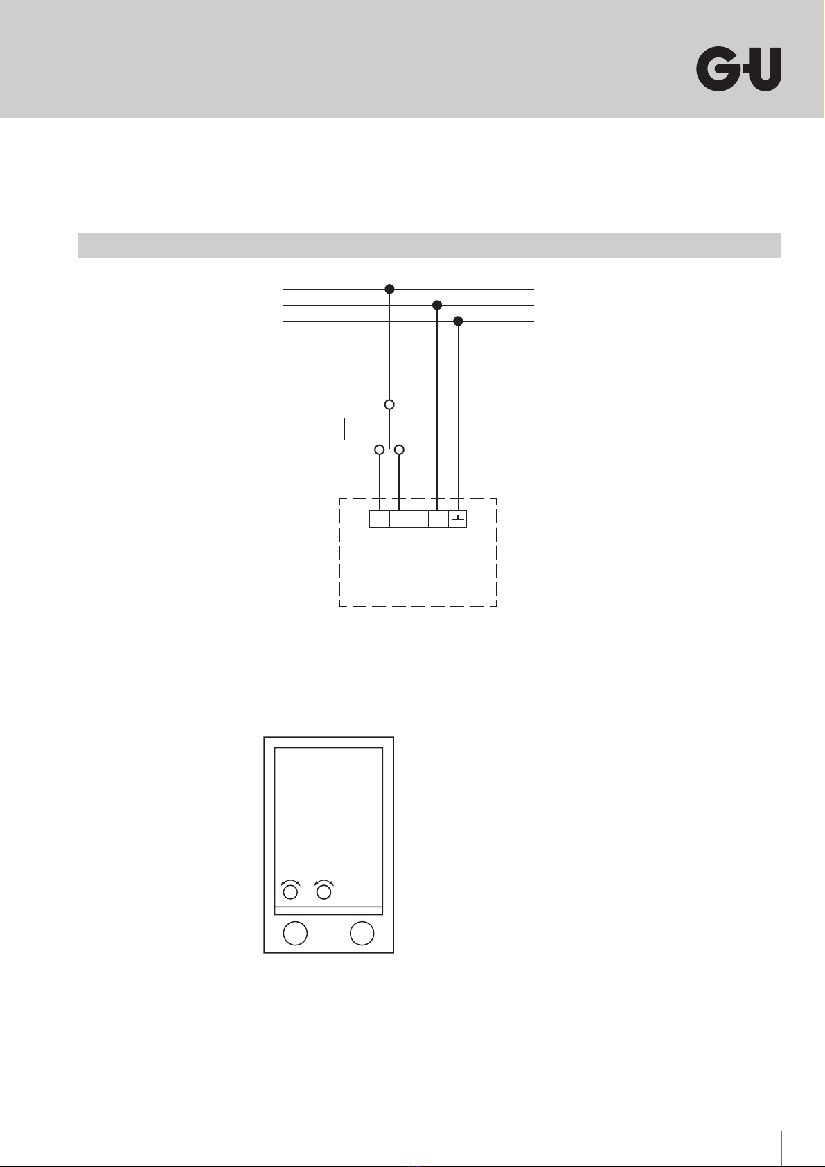
Schließen Sie den Antrieb gemäß Anschlussplan an.
Den Anschlussplan finden Sie am Ende dieser Anleitung. Befestigen Sie das Anschlusskabel
unbedingt mit der dafür vorgesehenen Zugentlastung!
Sollte während der Montage des Antriebs das Schutzleiterkabel von der Haube entfernt worden sein,
oder falls der Antrieb mit separater Haube ausgeliefert wurde, muss das Schutzleiterkabel wieder
mit der Haube elektrisch leitend verbunden werden. Es muss geprüft und protokolliert werden, dass
der Widerstand zwischen Haube und Klemme 5 (PE) max. 1 Ω entspricht gemäß DIN VDE 0100-600.
Je nach Einbauort, sind weitere länderspezifische Vorschriften zu beachten!
Der Antrieb ist für die Innenmontage geeignet und sollte grundsätzlich mit einem Regensensor
betrieben werden.
Setzten Sie nach der Montage die stirnseitigen Abdeckungen wieder auf. Schrauben Sie auf der
elektrischen Anschlussseite die Sicherungsschraube M3 wieder in die Kunststoffabdeckung ein, bis
die Sicherungsschraube eben mit der Oberfläche der Abdeckung ist!
4. Inbetriebnahme
Überprüfen Sie vor der ersten Inbetriebnahme, ob der Antrieb sachgemäß am Objekt befestigt
wurde (siehe Montage mechanisch und elektrisch) und der elektrische Anschluss gemäß den oben
genannten Bestimmungen ausgeführt wurde.
Achten Sie dabei auf die elektrische Zuleitung und prüfen Sie diese auf eventuelle Beschädigungen.
Lassen Sie die Zuleitung gegebenenfalls von einer Elektrofachkraft austauschen.
Sind die oben genannten Anforderungen erfüllt, können die beiden Endschalter eingestellt
werden. Die Endschalter werden durch Drehen mit einem Schraubendreher an den stirnseitigen
Stellschrauben verstellt (Drehrichtung siehe Anschlussplan). Die Endschalter müssen so eingestellt
werden, dass die Fenstermechanik und der Antrieb nicht auf Block belastet wird.
Die Endschalter sind im Auslieferungszustand passend für den GU Oberlichtöffner F 200 eingestellt.
Gegebenenfalls ist eine Feinjustierung notwendig.
Der Antrieb besitzt einen internen Thermoschalter, der bei Erreichen einer hohen Motortemperatur
den Antrieb abschaltet. Dies stellt eine Schutzmaßnahme des 230 V ~ Motors dar, die mechanische
Beschädigungen nicht ausschließt.
Bei der Hubeinstellung durch die Endschalter ist darauf zu achten, dass der jeweilige Endschalter
richtig abschaltet. Dann erlischt die Kontrollleuchte. Die Kontrollleuchte darf in den Endpositionen
nicht aufleuchten!
Prüfen Sie vor der Inbetriebnahme ob die beiden Endschalter sachgemäß eingestellt sind, um
Beschädigungen der Beschlags- oder Fensterkonstruktion zu vermeiden!
Sind beide Endschalter eingestellt, müssen Sie einen ersten Probelauf durchführen.

6DE
Elektroantrieb
Montage-, Betriebs- und Wartungsanleitung
ELTRAL S 230
07.2019 | G36582 | Designed in Germany
5. Betrieb
Die Nennlast wird nur bei Nennspannung erreicht. Eine Unterschreitung reduziert die Nennlast!
Betrieb mit einem "Totmanntaster"
Bei Betrieb mit einer "Totmannschaltung" (Tipp-Taster) muss eine Bestromung bis zum Ende des
Schließvorgangs erfolgen.
6. Wartung
Verwenden Sie keinesfalls Laugen oder Säuren zum Reinigen.
Alle 1000 Öffnungszyklen müssen folgende Prüfungen durchgeführt werden:
Prüfen Sie, ob alle Schrauben fest angezogen sind, bzw. ziehen Sie diese ggfs. nach.
Führen Sie eine Sichtkontrolle auf Beschädigung und Verschleiß aller Bauteile durch und tauschen
diese ggfs. aus.
Kontrollieren Sie die korrekte Einstellung der Endschalter.
Mindestens einmal pro Jahr eine Sichtprüfung des Netzkabels vornehmen. Es darf weder beschädigt
sein, noch dürfen sonstige Anzeichen von Verschleiß oder Defekten vorhanden sein.
Unterbrechen Sie die Strom- und Spannungsversorgung des Motors während den Reinigungs- und
Wartungsarbeiten.
Fetten Sie die Beschläge an den dafür vorgesehenen Stellen mit säurefreiem Fett.
Störungen beheben
Falls der Antrieb stehen bleibt, lassen Sie bitte die elektrische Versorgung durch eine
Elektrofachkraft überprüfen.
Tauschen Sie bei nicht von Fachleuten behebbaren Störungen den defekten Antrieb aus und lassen
ihn vom Herstellerwerk reparieren.
7. Ergänzende Dokumente
Einbauzeichnung Oberlichtöffner VENTUS F 200 0-43700
Einbauzeichnung Oberlichtöffner VENTUS F 200 mit Elektroantrieb ELTRAL S 0-48801
Einbauzeichnung Oberlichtöffner VENTUS F 200 Klappflügel 0-43818

7
8. Technische Daten
Versorgung 230 V ~ ± 10 %; 50 Hz
Stromaufnahme 0,4 A
Leistungsaufnahme 90 W
Einschaltdauer ED 25 % (150 s ON/450 s OFF)
Druckkraft bei 230 V ~ 1400 N
Zugkraft bei 230 V ~ (an M8-Gewindestange) 1400 N
Hublänge 50 mm (min. 27 mm – max. 70 mm)
Laufzeit AUF/ZU Ca. 1,2 mm/s bei 1400 N
Schutzart IP 20
Temperaturbereich -15 °C bis +70 °C
Überlastschutz Thermoschalter
Anschluss Anschlußstecker
Gehäuse Aluminium, Kunststoff
Abmessungen (B x H x L) 32,5 mm x 81,5 mm x 210 mm

8DE
Elektroantrieb
Montage-, Betriebs- und Wartungsanleitung
ELTRAL S 230
07.2019 | G36582 | Designed in Germany
210
81.5
191
108–133
63–83
10
81.5
18
16
14
32.5
14
5
Kontroll-
leuchte
Nut 10 mm tief
bei Endlage "ausgefahren"
110-133
bei Endlage "eingefahren"
4x DIN 74-Am5
2x Gewinde M8
in Spindelmutter
Sicherungs-
schraube M3
Haube
Bei Extremstellungen der Endschalter
(63 mm, 83 mm, 110 mm, 133 mm)
Haube abnehmen um festzustellen,
wann die maximale Stellung erreicht ist.
9. Abmessungen Antrieb

9
+–
+–
Endlage
"Eingefahren"
Endlage
"Ausgefahren"
10. Anschlussplan
Einstellen der Endschalter
Bei der Hubeinstellung durch Endschalter ist darauf zu achten, dass der jeweilige Endschalter richtig
abschaltet. Dann erlischt die Betriebsanzeige!
Kontrollleuchte darf in den Endpositionen nicht aufleuchten!
Die Einstellungen sind durch einen Probelauf zu überprüfen!
L1
N
PE
NLAE
ELTRAL S 230
230 V ~

10 EN
Electric drive
Installation, operation and maintenance instructions
ELTRAL S 230
07.2019 | G36582 | Designed in Germany
Table of contents
1. Fundamental informations......................................................... Page 11
2. Safety instructions...................................................................... Page 11
3. Mounting..................................................................................... Page 12
4. Initial Operation ......................................................................... Page 13
5. Operation.................................................................................... Page 14
6. Maintenance ............................................................................... Page 14
7. Further documents ..................................................................... Page 14
8. Technical data ............................................................................. Page 15
9. Dimensions of drive.................................................................... Page 16
10.Connection Diagram................................................................... Page 17
Please pass the document on to the user

11
1. Fundamental informations
This assembly and operating manual is a component of the product.
The drive may be used exclusively for the opening and closing of windows.
Please read this manual carefully and pay particular attention to the safety instructions before
proceeding with the assembly, maintenance or use of the drive.
Please keep the manual at your disposal throughout the drive’s lifespan.
The drives comply with the state-of-the-art technology prevailing at the time of delivery. This applies
to the performance, material, functionality and safe operation of the drives. The competent and
safety-conscious conduct of the assemblers and installers is essential in order to ensure the safe
assembly and installation of the drives.
Installation drawings that explain how the hardware and electric drive is installed are available for
the hardware used by Gretsch-Unitas. Please refer to these drawings when installing our electric
drives.
Use of the electric drive for other purposes must be approved by Gretsch-Unitas GmbH
Baubeschläge. Make sure that the hinges and hardware used permit the opening travel of the
electric drive as otherwise they could be damaged by pull or push forces.
The permissible sash weight and sash size for the hardware being used must be observed.
2. Safety instructions
The drive is intended to be used solely for the opening and closing of windows.
Please bear in mind during assembly and operation:
Assembly and initial operation may only be carried out by qualified professionals!
Pay regard to all applicable regulations, e.g.
Accident prevention regulations
VDE Regulations
DIN- and EN-Norms
Occupational safety regulations etc.
Only use the drive if in a technically immaculate condition, in accordance with the applicable
regulations, in a safety- and danger-conscious manner and in strict accordance with the assembly
and operating manual.
Please note that during the assembly and disassembly of the drive, the respective window must be
secured to prevent it from unintentionally tilting or slamming shut.
Crushing and Pinch Point Hazard for Fingers:
The window closes automatically. During assembly and operation, do not reach into the window
rebate and the moving output shaft. The limiting switch stops the drive during opening and closing.
Please refer to the technical data section for the corresponding compressive force values. This is
enough to result in injured limbs due to carelessness.
Caution
In order to ensure the flawless functionality of the drives at any time, always take potential loads
(e.g. caused by snow or wind) into consideration that may rest on the window.

12 EN
Electric drive
Installation, operation and maintenance instructions
ELTRAL S 230
07.2019 | G36582 | Designed in Germany
3. Mounting
3.1 Mechanical
The assembly may only be carried out by trained professionals.
Remove the plastic covers on the front and rear of the drive by pulling them off in an upwards
direction.
Fasten the drive using the designated screw drill holes (4x) with an M5 or woodscrew up to d = 5 mm.
Fit the drive onto the window in such a way that it is accessible at any given time, and can be
exchanged if necessary.
For the transmission of force onto the window the rod is screwed into the spindle nut on the frontal
side (e.g. for fanlight openers). In order to do this, remove one of the frontal cover plugs.
For the assembly and installation of the drives, please bear the following in mind:
The required performance values (please see “Technical Data”) may be neither exceeded nor
undershot.
The values indicated on the dimension sheet are to be complied with during the installation of the
drive.
Be sure to verify whether your facility meets the necessary technical and electric requirements.
Always respect all country specific regulations for electric governance systems as well as all other
country specific regulations.
Always verify whether your facility meets the relevant requirements.
Pay special attention to the:
Cross-section of the window
Opening time/speed
Temperature resistance of the cables and drive
Cross-section of the cables in the governance system
The window and window frame must be constructed according to the strain caused by the
compressive and tractive force of the drive.
Danger during assembly
The warranty for the safe operation is dependent on the assemblers’ compliance with the safety
regulations. The handling and assembly of certain parts and components in an inappropriate manner
may lead to injuries under unfavourable circumstances.
Risk of injury through improper handling! Potential injury through crushing, shearing, cutting,
impact!
Follow the general construction and safety instructions for handling and assembly.
Use suitable assembly and transport facilities.
Prevent incarceration and crushing through suitable precautions.
Only use suitable tools.
Use lifting equipment and tools properly.
Use appropriate safety equipment (e.g. safety goggles, safety shoes) when necessary.
Do not stop beneath hanging loads.

13
3.2 Electric
Caution
Only operate the drive with 230 V ~.
The electric installation may only be carried out by professional electricians while following the
safety regulations. The connection cables may not be put under the strain of twisting, crushing or
shearing off.
In case it has not yet been done, remove the safety screw M3 on the frontal plastic cover on the side
of the electric connection. Remove the plastic covers by pulling them off in an upward direction.
Connect the drive according to the connection diagram. The detailed connection diagram is located
at the end of this manual. It is crucial that the connection cable is fastened using the designated
strain relief!
In case of disconnecting the ground wire from the cover during mounting the drive or in case
of separate delivery of the cover and the drive, the ground wire must be connected electrically
conducting. It must be tested and recorded that the electrical resistance between the cover and
terminal 5 (PE) is max. 1 Ω according DIN VDE 0100-600. According to the place of installation,
further country-specific regulations must be observed!
The drive is suitable for interior mounting and should principally operate with a rain-sensor.
After assembly, be sure to place the front and rear covers back onto the drive. It is essential that you
screw the safety screw M3 back into the plastic cover on the side of the electric connection. Do this
until the screw is even with the surface of the cover.
4. Initial Operation
Before putting the drive into operation for the first time, please verify whether the drive has been
properly fixed onto the respective object (please see Assembly mechanical and electric) and whether
the electric connection was carried out in accordance with the requirements listed above.
Pay attention to the electric supply cables and inspect these for potential damage. If necessary, have
a professional electrician exchange the supply cables.
If the requirements listed above have been met, the two limiting switches may be adjusted. The
limiting switches are adjusted by turning the frontal setting screws using a screwdriver (refer to
connection diagram for turning direction). The limiting switches must be adjusted in such a way that
the window mechanics and the drive are not strained to block.
In the delivery condition, the limit switches are set to fit the fanlight opener F 200. If necessary, a
fine adjust is required.
The drive has an internal thermal switch. When reaching a high motor temperature, the drive
switches off. This is a overload protection for the 230 V ~ motor, which does not exclude mechanical
damages.
During the stroke adjustment through the limiting switches, make sure that the respective limiting
switch has switched off correctly. If this is the case, the control lamp will switch off. The control lamp
may not switch on in the final positions!
Before commencing with the initial operation, verify whether the two limiting switches have been
adjusted correctly in order to avoid damage being caused to the fitting or window construction!
Once both limiting switches have been adjusted, you must conduct a first trial run.

14 EN
Electric drive
Installation, operation and maintenance instructions
ELTRAL S 230
07.2019 | G36582 | Designed in Germany
5. Operation
The nominal load is only reached under the nominal voltage. Falling under the nominal voltage
reduces the nominal load.
Operation with a "dead man’s push button"
During operation with a "dead man’s switch", current feeding must take place until the end of the
closing process.
6. Maintenance
Under no circumstances should alkaline or acidic solutions be used for cleaning purposes.
The following tests need to be carried out after every 1000 opening-cycles:
Inspect whether all screws are tightly fastened and retighten them if necessary.
Visually inspect all components for any signs of damage or wearing out, and replace these if
necessary.
Ensure that the limiting switches are set correctly.
At least once a year, conduct a visual inspection of the power cable. It may not be damaged, nor may
any signs of wearing out or faults exist.
Discontinue the current and power supply of the motor during the cleaning and maintenance
process.
Apply grease to the hardware at the designated points using acid-free grease.
Rectifying disturbances
In case the drive stops running, please have a professional electrician examine the electricity supply.
If the disturbances cannot be rectified by qualified professionals, replace the faulty drive and have
the manufacturer repair it.
7. Further documents
Installation drawing fanlight opener VENTUS F 200 0-43700
Installation drawing fanlight opener VENTUS F 200 with electric drive ELTRAL S 0-48801
Installation drawing fanlight opener VENTUS F 200 Top-Hung sash 0-43818

15
8. Technical data
Supply 230 V ~ ± 10 %; 50 Hz
Current consumption 0.4 A
Power input 90 W
Duty ratio ED 25 % (150 s ON/450 s OFF)
Compressive force at 230 V ~ 1400 N
Tractive force at 230 V ~ (at M8- threaded rod) 1400 N
Stroke lentgth 50 mm (min. 27 mm – max. 70 mm)
Running time OPEN / CLOSE Approx. 1.2 mm/s at 1400 N
Protection type IP 20
Temperature range -15 °C to +70 °C
Overload protection Thermal switch
Connection Connector
Casing Aluminium, Plastic
Dimensions (w x h x l) 32.5 mm x 81.5 mm x 210 mm

16 EN
Electric drive
Installation, operation and maintenance instructions
ELTRAL S 230
07.2019 | G36582 | Designed in Germany
210
81.5
191
108–133
63–83
10
81.5
18
16
14
32.5
14
5
Control
lamp
groove 10 mm deep
at final position "extended"
110-133
at final position "retracted"
4x DIN 74-Am5
2x thread M8
in spindle nut
Safety
screw M3
Cover
Remove cover when adjusting extreme
positions of the switches
(63 mm, 83 mm, 108 mm, 133 mm),
in order to recognize when the maximum
positions is reached.
9. Dimensions of drive

17
+–
+–
Final position
"retracted"
Final position
"extended"
10. Connection Diagram
Adjusting the limited switches
During the stroke adjustment through the limiting switches, make shure that the respective limiting
switch has switched off correctly. If this is the case, the control lamp will switch off.
The control lamp may not switch on the final positions.
The adjustements must be controlled ba a trial run!
L1
N
PE
NLAE
ELTRAL S 230
230 V ~

18
ELTRAL S 230
07.2019 | G36582 | Designed in Germany

19

Herausgeber | Editor:
Gretsch-Unitas GmbH
Baubeschläge
Johann-Maus-Str. 3
D-71254 Ditzingen
Tel. + 49(0)7156 301-0
Fax +49 (0) 7156 3 01-293
www.g-u.com
Fehler, Irrtümer und technische Änderungen vorbehalten |
Errors and omissions reserved. Subject to technical modifications
DiedemProduktbeiliegendentechnischenUnterlagenentsprechendemStandzumZeitpunktderHerstellungdesProdukts.UnsereProduktewerdenständigweiterentwickelt. Prüfen
Siedeshalbauf www.g-u.com,ob die Ihnen vorliegenden technischen Unterlagen auf dem neuesten Standsind. Verwenden Sie ausschließlich die aktuellstentechnischen Unterlagen |
The documents accompanying the product were issued when the product was manufactured. Due to the fact that our products undergo continuous development, you should verify
at www.g-u.com, if the technical documents you have at hand are up to date. Be sure to use the latest edition of our technical documents.
Vorsprung mit System
Securing technology for you
Table of contents
Languages:
Other G-U DC Drive manuals
Popular DC Drive manuals by other brands

National Instruments
National Instruments NI SMD-7613 Getting started

PXM
PXM PX268+ user manual

American Control Electronics
American Control Electronics MTU400-11.5 quick guide

Danfoss
Danfoss VLT Automation Drive FC 360 Programming guide

Nord Drivesystems
Nord Drivesystems NORDAC PRO user manual

SOMFY
SOMFY Roll Up 24 WF RTS Li-ion instructions

Hytronik
Hytronik HED1050L instruction manual

Iomega
Iomega Zip 750MB Quick install

WEG
WEG CFW-11 Series Installation and operation guide

easydriver
easydriver basic 1.8 Installation and instruction manual

Danfoss
Danfoss VLT AutomationDrive FC 301 instruction manual

Siemens
Siemens 3TL60 operating instructions