3 / 94FAVERO ELECTRONICS - 160826 - 00304-M02-03 - ML-FC serie scoreboards - User Manual Rev03
ENGLISH
Model Display Size [cm]
Width x Height x Depth Weight
[kg] Power
[A]/[VA]
FC50H20
Art.
3045020
Team scores [0 ~ 199]: digits 20cm high
Timer [0:00 ~ 99:59]: digits 20cm high
Period [0 ~ 9]: digit 15cm high
Team fouls / Sets won [0 ~ 9]: digits 15cm high
Timeouts [3 indicators]: diameter 1.5cm
Possession / Service / Turn [1 indicator]: diameter 2cm
140 x 73 x 9 21 1.4 / 140
FC54H20
Art.
3045420
Team scores [0 ~ 199]: digits 20cm high
Timer [0:00 ~ 99:59]: digits 20cm high
Period [0 ~ 9]: digit 15cm high
Team fouls / Sets won [0 ~ 99] or Penalty times [0:00 ~ 9:59]: digits 15cm high
Timeouts [3 indicators]: diameter 1.5cm
Possession / Service / Turn [1 indicator]: diameter 2cm
140 x 108 x 9 30 1.5 / 165
FC56H20
Art.
3045620
Team scores [0 ~ 199]: digits 20cm high
Timer [0:00 ~ 99:59]: digits 20cm high
Period [0 ~ 9]: digits 15cm high
Team fouls / Sets won [0 ~ 9]: digits 15cm high
Penalty times [0:00 ~ 9:59]: digits 15cm high
Timeouts [3 indicators]: diameter 1.5cm
Possession / Service / Turn [1 indicator]: diameter 2cm
140 x 133 x 9 36 1.8 / 200
FC50H25
Art.
3045025
Team scores [0 ~ 199]: digits 25cm high
Timer [0:00 ~ 99:59]: digits 25cm high
Period [0 ~ 9]: digit 20cm high
Team fouls / Sets won [0 ~ 9]: digits 20cm high
Timeouts [3 indicators]: diameter 2.5cm
Possession / Service / Turn [1 indicator]: diameter 2.5cm
140 x 83 x 9 22 1.5 / 160
FC50H25N
Art.
3045425N
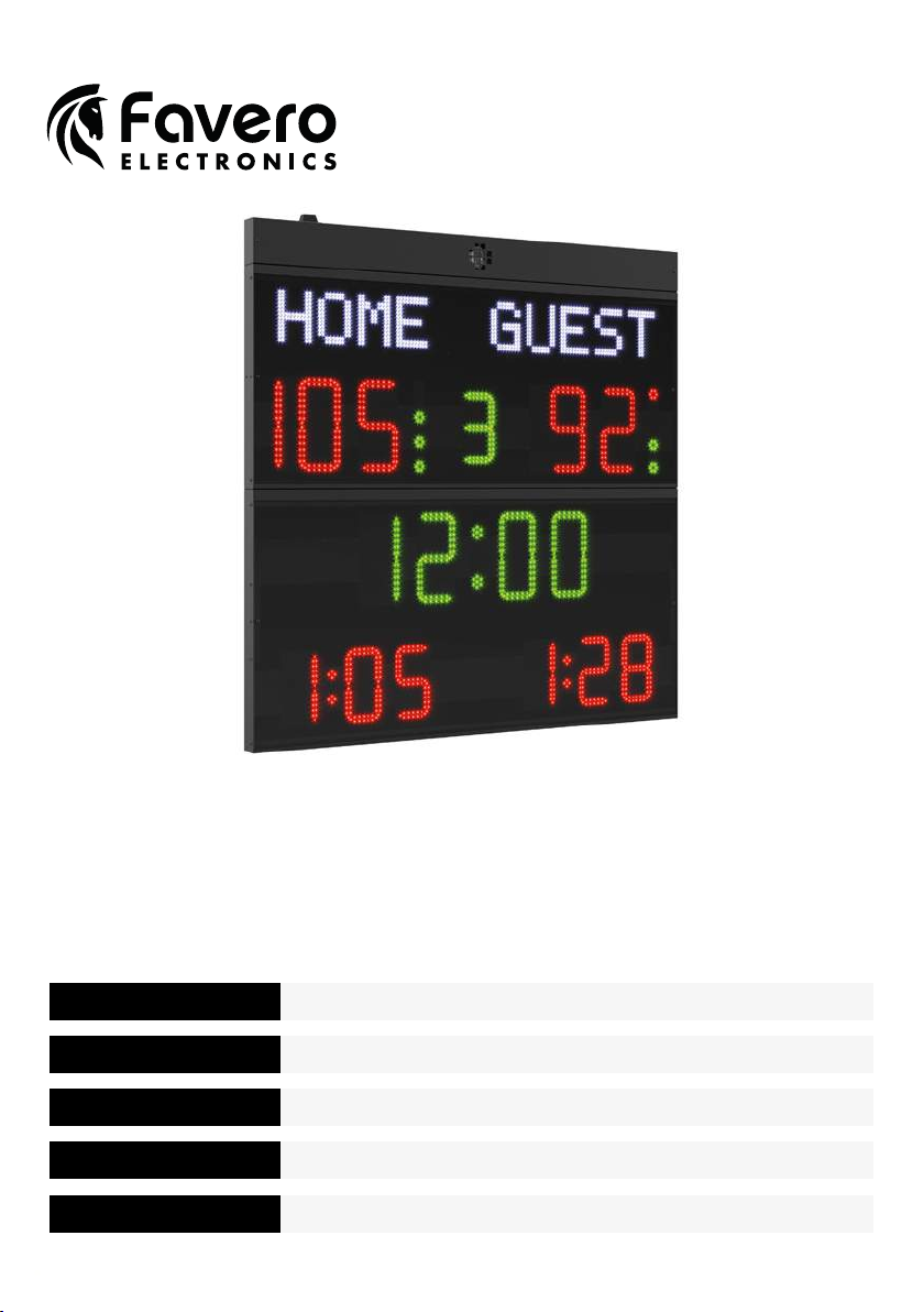
Team names [6 characters per team]: 16cm high
Team scores [0 ~ 199]: digits 25cm high
Timer [0:00 ~ 99:59]: digits 25cm high
Period [0 ~ 9]: digit 20cm high
Team fouls / Sets won [0 ~ 9]: digits 20cm high
Timeouts [3 indicators]: diameter 2.5cm
Possession / Service / Turn [1 indicator]: diameter 2.5cm
140 x 108 x 9 33 1.9 / 215
FC54H25
Art.
3045425
Team scores [0 ~ 199]: digits 25cm high
Timer [0:00 ~ 99:59]: digits 25cm high
Period [0 ~ 9]: digit 20cm high
Team fouls / Sets won [0 ~ 99] or Penalty times [0:00 ~ 9:59]: digits 20cm high
Timeouts [3 indicators]: diameter 2.5cm
Possession / Service / Turn [1 indicator]: diameter 2.5cm
140 x 118 x 9 32 1.8 / 200
FC54H25N
Art.
3045425N
Team names [6 characters per team]: 16cm high
Team scores [0 ~ 199]: digits 25cm high
Timer [0:00 ~ 99:59]: digits 25cm high
Period [0 ~ 9]: digit 20cm high
Team fouls / Sets won [0 ~ 99] or Penalty times [0:00 ~ 9:59]: digits 20cm high
Timeouts [3 indicators]: diameter 2.5cm
Possession / Service / Turn [1 indicator]: diameter 2.5cm
140 x 143x 9 40 2.1 / 255
FC60H25N
Art.
3046025N
Team names [6 characters per team]: 16cm high
Team scores [0 ~ 199]: digits 25cm high
Timer [0:00 ~ 99:59]: digits 25cm high
Period [0 ~ 9]: digit 20cm high
Team fouls / Sets won [0 ~ 9]: digits 20cm high
Player numbers[0 ~ 99] + Penalty times [0:00 ~ 9:59]: digits 15cm high
Timeouts [3 indicators]: diameter 2.5cm
Possession / Service / Turn [1 indicator]: diameter 2.5cm
140 x 168 x 9 48 3.6 / 330
FC62H25N
Art.
3046225N
Team names [6 characters per team]: 16cm high
Team scores [0 ~ 199]: digits 25cm high
Timer [0:00 ~ 99:59]: digits 25cm high
Period [0 ~ 9]: digit 20cm high
Team fouls / Sets won [0 ~ 9]: digits 20cm high
Player numbers[0 ~ 99] + Penalty times [0:00 ~ 9:59]: digits 15cm high
Timeouts [3 indicators]: diameter 2.5cm
Possession / Service / Turn [1 indicator]: diameter 2.5cm
140 x 178 x 9 52 3.9 / 375
Table 1a.