RNA FP 120 User manual

,
Installation instructions
for
Belt conveyors
FP 120
FK 120

Rhein-Nadel Automation GmbH 2
VT-BA-FP120-EN_2020 / 02.03.2020 SJ
Table of Contents
1. Technical data........................................................................................................................4
1.1. Table...................................................................................................................................4
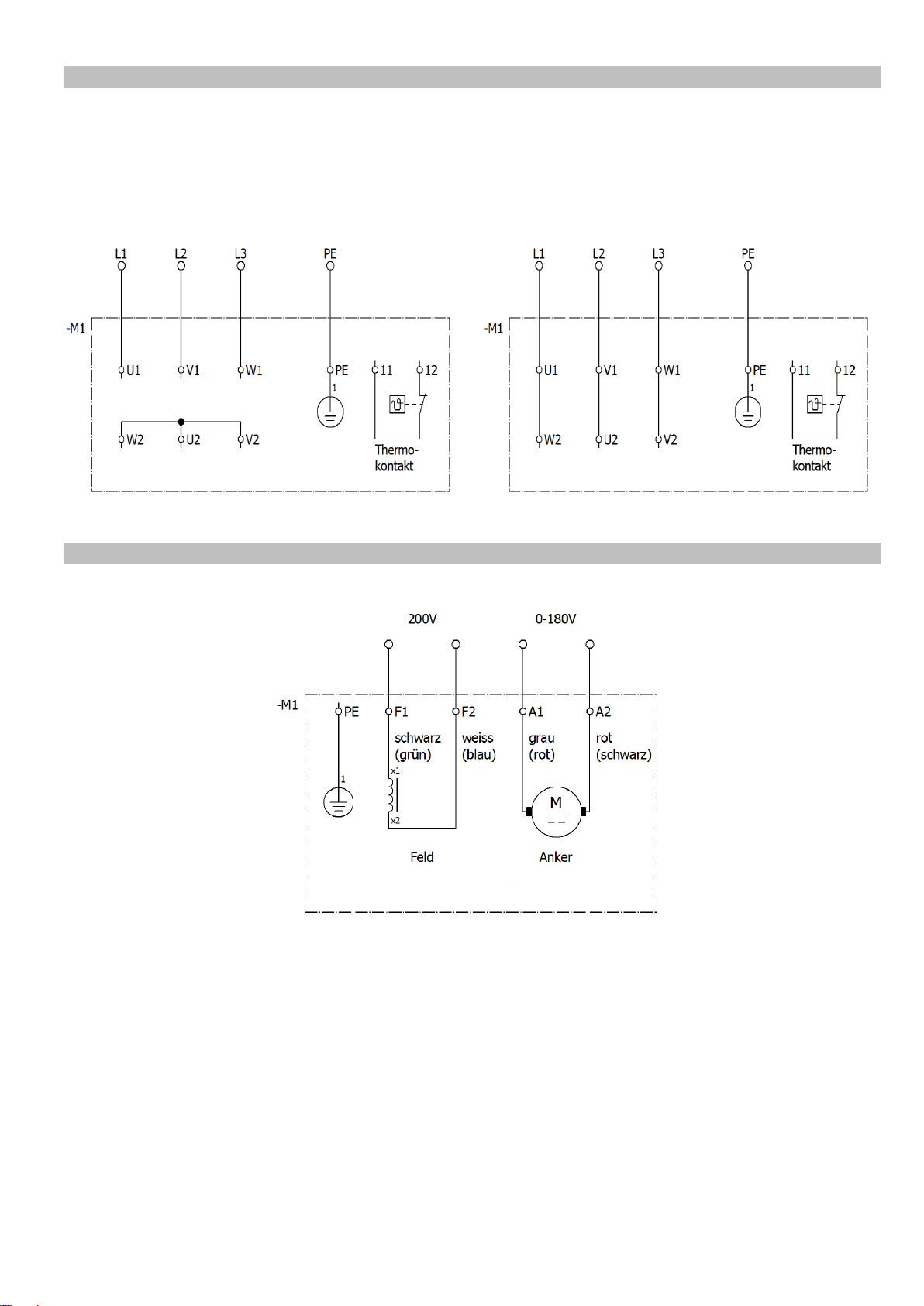
1.2. Motor connection diagrams.................................................................................................5
1.2.1. Constant-speed three-phase motor..............................................................................5
1.2.2. Constant-speed A.C. motor (with capacitor)................................................................. 5
1.2.3. Variable-speed three-phase motor...............................................................................6
1.2.4. D.C. motor....................................................................................................................6
2. Safety directives.....................................................................................................................7
2.1. Applicable directives and standards....................................................................................9
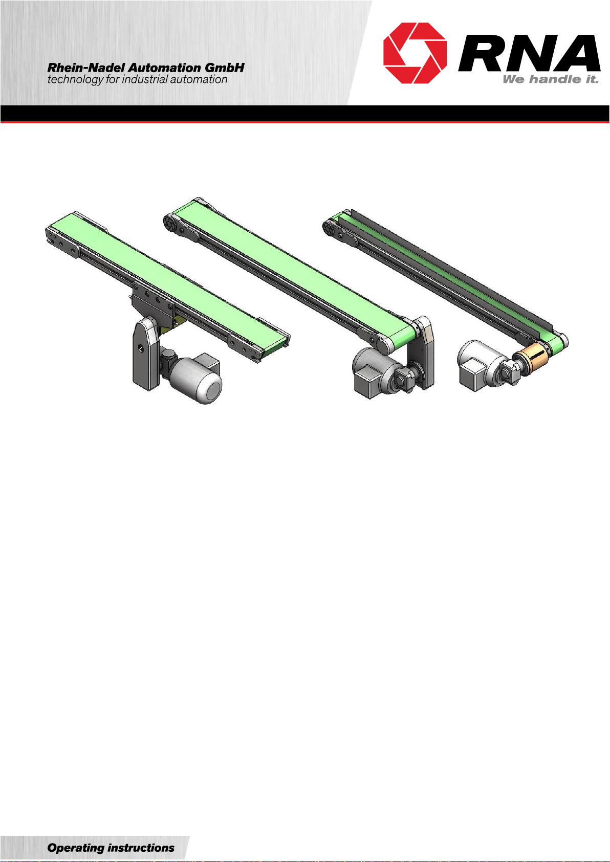
3. Design and functional description of belt conveyors ..............................................................9
4. Shipment and installation.....................................................................................................11
4.1. Shipment...........................................................................................................................11
4.2. Installation.........................................................................................................................11
4.2.1. One-piece belt feeders...............................................................................................11
4.2.2. Installation of multi-segment belt feeders...................................................................11
4.2.3. Installation on RNA supports......................................................................................13
4.2.4. Drive system (belt conveyors without RNA control units)...........................................14
4.2.5. Preliminary adjustment of belt tracking.......................................................................14
5. Commissioning.....................................................................................................................15
5.1. Adjustment of belt return station .......................................................................................15
5.2. Adjusting the center drive station......................................................................................16
5.3. Adjusting at the head drive station (reserved only for exceptional situations)...................16
5.4. Changing the sense of rotation.........................................................................................16
6. Belt replacement..................................................................................................................17
6.1. Replacing a belt with head drive station............................................................................17
6.2. Replacing a belt with center drive station..........................................................................17
7. Maintenance.........................................................................................................................18
7.1. Belt....................................................................................................................................18
7.2. Motor.................................................................................................................................18
7.3. Gearbox............................................................................................................................18
7.4. Chain drive system ...........................................................................................................19
7.5. Return, drive and supporting rollers..................................................................................19
7.6. Environmental effects .......................................................................................................19
8. Spare parts and customer service........................................................................................19

Rhein-Nadel Automation GmbH 3
VT-BA-FP120-EN_2020 / 02.03.2020 SJ
Declaration of Incorporation
according to Machinery Directive 2006/42/EC
We hereby declare that our product is intended to be incorporated into or assembled with other machinery to consti-
tute one machine in terms of the Directive indicated above (or parts thereof) and that it must not be put into operation
until the relevant machinery into which it is to be incorporated has been declared to be in conformity with the EC Ma-
chinery Directive.
Applied harmonised standards: DIN EN 60204 T1, DIN EN ISO 12100-2011-03, DIN EN 619, DIN EN 620
DIN EN 1050
Remarks:
This product has been manufactured in accordance with the Low-Voltage Directive 2014/35/EU.
We assume that our product will be incorporated into a stationary machine.
Rhein-Nadel Automation GmbH
Managing Director
Jack Grevenstein

Rhein-Nadel Automation GmbH 4
VT-BA-FP120-EN_2020 / 02.03.2020 SJ
1. Technical data
1.1. Table
Belt widths
(mm)
50, 80, 100, 120, 150, 200, 250, 300, 400, 500
(intermediate widths and widths > 500 are possible)
Belt lengths = shaft center distance
(mm)
500 to 12,000
(smaller sizes possible depending on design)
Conveyor load
(N/m)
100 standard rating
(depending on motor, belt width and mode of operation
(conveyance or accumulation) the total load may be
much higher)
Constant belt speed
Three-phase motor
230/400V +10 %, 50/60Hz, IP54
(m/min.)
0.5, 1, 2, 3, 4, 5, 6, 7, 8, 10, 15, 20, 30, 50, 60, 80
(other speeds possible)
Constant belt speed
A.C. motor
230V, 50/60Hz, IP54
(m/min)
0.5, 1, 2, 3, 4, 5, 6, 7, 8, 10, 15, 20, 30, 50, 60, 80
(other speeds possible)
Variable belt speed
Three-phase motor with frequency control
230V or 400V, depending on VFD used
(m/min.)
0.25-1 / 0.5-2 / 1.25-5 / 2.5-10 / 5-20 / 7.5-30 / 15-60 /
20-80
(other speeds possible)
Variable belt speed
D.C. motor
0-180V armature 200V field, IP54
(m/min.)
0.25-1 / 0.5-2 / 1.25-5 / 2.5-10 / 5-20 / 7.5-30
(other speeds possible)
Current input
see rating plate
Roller diameter
(mm)
return rollers 52
knife edges 8
Tensioning station
Integrated in belt return station and center drive sta-
tion, with additional center tensioning station for belt
lengths 5,000 mm

Rhein-Nadel Automation GmbH 5
VT-BA-FP120-EN_2020 / 02.03.2020 SJ
1.2. Motor connection diagrams
1.2.1. Constant-speed three-phase motor
Connection of three-phase motors
For reversing the sense of rotation change two phases of the supply line
1.2.2. Constant-speed A.C. motor (with capacitor)
Connection of three-phase motors
Connection to three-phase supply
Low voltage (delta connection)
3x230V
Connection to three-phase supply
High voltage (star connection)
3x400V
Connection to a.c. supply
1x230V
CW rotation
Connection to a.c. supply
1x230V
CCW rotation

Rhein-Nadel Automation GmbH 6
VT-BA-FP120-EN_2020 / 02.03.2020 SJ
1.2.3. Variable-speed three-phase motor
Connection of variable-speed three-phase motors via variable frequency drive unit
For reversing the sense of rotation change two phases of the supply line
1.2.4. D.C. motor Connection of D.C. motors
To reverse the sense of rotation invert the field leads.
(colour specs between parentheses apply to SN3FG)
Connection to three-phase supply
Low voltage (delta connection)
3x230V
Connection to three-phase supply
High voltage (star connection)
3x400V

Rhein-Nadel Automation GmbH 7
VT-BA-FP120-EN_2020 / 02.03.2020 SJ
2. Safety directives
We have taken great care in design and manufacture of our conveyors in order to ensure smooth and safe operation.
You, too, can make an important contribution towards safety at work. We therefore ask you to read these brief operating
instructions completely prior to commissioning the system. Observe the safety directives at all times!
Attention
This warning sign indicates safety directives. Non-observance of such warnings may cause serious injury or
even death!
Caution
This warning sign indicates safety directives. Non-observance of this warning may cause minor injury or
material damage.
Notice
This hand indicates useful tips for operation of the conveyors.
Make sure that all persons working with or at the equipment also read the following safety directives carefully and follow
them!
These Operating Instructions only apply to the equipment types indicated on the cover page.
They must be available at all times at the place of installation of the conveyor.
If the conveyor is to be used in a humid or wet environment (wet area) make sure that the required degree of protection
is provided.
Notice
For comprehensive information on the full range of control devices please refer to the 'Control Units' operat-
ing instructions.
Any commissioning, retooling, maintenance and repair work shall be carried out by qualified and authorized personnel
only (see also 'Operator's duties' in this section).
For installation, maintenance and repair work all poles of the power supply must be disconnected from the conveyor in
compliance with VDE provisions.
Any work on the electrical equipment shall be carried out exclusively by a professional electrician, or by instructed
persons working under the supervision of a professional electrician, according to electrotechnical rules.
Attention
Risk of injury and electric shock hazard!
•The equipment user and operators shall ensure that only authorized personnel works at the conveyor.
•Any changes that have occurred on the feeding system affecting safety shall immediately be reported to the
user.
•Operate the conveyor in perfect condition only.
•Use the belt conveyor only for its intended use.
•Observe the accident prevention provisions VBG 10 for continuous conveyors and VBG 4 for electrical equip-
ment and components"
Machine hazards
•If the belt conveyor comes into contact with moisture or liquids there is risk of electric shock.
•Make sure that protective earthing of the power supply system is in perfect condition.
•Never operate the conveyor without guards and cover panels in place!

Rhein-Nadel Automation GmbH 8
VT-BA-FP120-EN_2020 / 02.03.2020 SJ
Intended use
The intended use of the belt conveyors is the feeding of parts.
The shortest side of such parts must be at least 5 mm long. Special versions or accessory equipment are available to
modify the belt conveyors for use with parts having smaller side lengths (> 0.5 mm). If necessary, please contact the
manufacturer.
Caution
Smaller parts may get under the belt and cause damage or failure of the belt conveyor.
Parts handled with standard belts must be dry, clean and without sharp edges. The handling of sharp-edged, oily, wet
or hot (>70°C) parts requires the use of special belts.
Caution
For handling parts that may fall over, roll or slide, be sure to install sufficiently dimensioned side guides or
slatted belts from our range of accessories.
The parts must not drop on the conveyor belt from height. The maximum permitted impact energy is 0.1 J.
If in doubt, please contact the manufacturer.
The belt conveyors are designed for horizontal transport at maximum loading. A slight inclination of the conveyor is
possible in some cases. Please consult the manufacturer to determine what is possible for your specific application!
For permitted belt loading see Technical Data in section 1.
Noise emission
The constant sound pressure level is 70 dB(A) max. Specific part handling applications or belt designs may result in
higher noise levels. For such exceptional cases noise abatement options are available from manufacturer.
Equipment user's duties
Commissioning, retooling, maintenance and repair work shall be performed by qualified and authorized personnel only.
We distinguish between four qualification levels:
Qualified personnel
refers to persons who are familiar with installation, start-up and operation of the conveyor. Their qualifications are ap-
propriate for their activities.
Authorized personnel
refers to qualified personnel that has been assigned a clearly defined task by the user of the belt conveyor.
Qualified electrical worker
According to IEC 364 and DIN VDE 0105 Part 1, the term 'qualified electrical worker' refers to persons who, through
their professional training, know-how and experience and through their knowledge of applicable standards are able to
assess the work assigned to them and to recognize potential hazards.
Instructed person
According to IEC 364 and DIN VDE 0105 Part 1, the term 'instructed person' refers to persons who have been instructed
in the tasks assigned to them by a qualified electrical worker. These persons have also been briefed on potential dangers
resulting from inappropriate behaviour, and on the requisite guards and precautions to be used/taken.

Rhein-Nadel Automation GmbH 9
VT-BA-FP120-EN_2020 / 02.03.2020 SJ
2.1. Applicable directives and standards
The hopper has been manufactured in accordance with the following directives:
•EC Machinery Directive 2006/42/EC
•EC Low-Voltage Directive 2014/35/EU
•Electromagnetic Compatibility Directive 2014/30/EU
We assume that our product will be incorporated into a stationary machine. The requirements of the EMC Directive
must be satisfied by the user.
The applicable standards are specified in the Declaration of Incorporation.
3. Design and functional description of belt conveyors
The belt conveyor bodies are made up of either special T-slotted aluminium profiles (FP120) or a folded sheet metal
body (FK120).
Fig. 1: Conveyor body types
Up to belt widths of 200 mm the conveyors can be fitted with knife edges at the entry and exit ends. If a knife edge is
fitted it is not possible to arrange a drive station at the respective location. Belt tension and tracking are adjustable by
means of the return roller arranged underneath the knife edge (see arrow).
Fig. 2: Knife edge
FP120 profile body
FK120 sheet metal body

Rhein-Nadel Automation GmbH 10
VT-BA-FP120-EN_2020 / 02.03.2020 SJ
For belt drive a number of motors are available for constant and variable speed. The motor may be arranged at the entry
or exit end of the belt or in the middle. Drive stations can be attached to the belt conveyor in different ways. Control of
the belt feeder is effected, depending on motor type, by motor protection breaker, electronic control devices or variable-
frequency control units.
Fig. 3: Drive configurations
After loosening the setscrews (see arrow) you can rotate the drives on the driving roller shaft for variable motor position-
ing. Re-tighten the setscrews to fix it back in place. Adjusting the chain drive may affect chain tension. Therefore be sure
to always check and adjust chain tension before restarting.
Notice
For information on the control devices please refer to the separate 'Control Units' operating instructions.
The brackets of the return station come with or without edge protectors. Brackets without edge protectors are smaller
in size and are used when parts or side guides extend beyond the brackets, or for belts installed in hopper-type feeders.
Belt tension and tracking are adjustable by means of the return roller (see arrow).
Fig. 4: Return station brackets
Depending on the application on hand the different belt feeders can be fitted with various accessories.
These include cleated belts, anti-slip belts, reversible belts, angled belts, ESD versions, pharmaceutical versions, split
conveyor bodies, side guides, top covers, sealing bars, supporting rollers, dirt trays, various support types etc.
Drive with chain
Direct-drive with flexible coupling
Direct-drive station without coupling
only for belt speeds up to 2m/min
Brackets with edge protector
Brackets without edge protector

Rhein-Nadel Automation GmbH 11
VT-BA-FP120-EN_2020 / 02.03.2020 SJ
4. Shipment and installation
4.1. Shipment
Shipment ex works
The belt conveyors are delivered ex works in cardboard or box packaging.
Handling on site
The belt conveyor weight depends on its dimensions and motor rating. Please refer to the shipping documents for the
weight of your specific equipment.
Attention
Check all guards when unpacking. Replace any damaged parts before commissioning!
Caution
One-piece belt conveyors can be moved to their place of installation on a sufficiently strong trolley or cart. It
is prohibited to move or handle multi-segment belt feeders in a fully assembled state!
4.2. Installation
4.2.1. One-piece belt feeders
One-piece belt feeders are delivered fully assembled. The procedure for installation on RNA-supplied supports is de-
scribed in section 4.2.3.
4.2.2. Installation of multi-segment belt feeders
RNA belt feeders whose total length exceeds 3 m are delivered in segments due to packing and shipping considerations.
The installation procedure for these belt feeders is described below.
Installation of the conveyor body
•Match the joints having the same numbers (Fig. 1).
Fig. 5: Assembly of individual components
•If the skid plates are to be fixed in place with adhesive, peel the plastic coat off the double-sided bonding tape.
Lift one conveyor body and slide it over the adjacent conveyor body so that their profiles are properly aligned and
touch each other. In this position, press the skid plate onto the double-sided bonding tape. You can now join the
conveyor bodies together by tightening the bolts (see arrow). Be sure to re-check the profiles for correct alignment.
•You can now slide the belt over the conveyor bodies from one side (observe notice below).
Notice
The standard belts are fabricated with finger joints to create a continuous belt. For such belts the conveying
direction can be chosen freely.

Rhein-Nadel Automation GmbH 12
VT-BA-FP120-EN_2020 / 02.03.2020 SJ
For belts with overlap joints the conveying direction should be as shown below.
Fig. 6: Choice of conveying direction
Use of the belt for accumulation of parts is an exception. In this case, turn the belt.
Fig. 7: Accumulation belt conveying direction
•Align the conveyor body segments with each other (Fig. 4).
Fig. 8: Aligning the belt conveyor
•Join the conveyor body segments together.
•Align the drive and return rollers relative to one another and to the conveyor body (Fig. 9).
Fig. 9: Roller alignment
Caution
Install the guard enclosure before starting up the belt conveyor!

Rhein-Nadel Automation GmbH 13
VT-BA-FP120-EN_2020 / 02.03.2020 SJ
4.2.3. Installation on RNA supports
For installation of the belt conveyor on the RNA-supplied supports proceed as follows:
Fig. 10: Support types
•Adjusting the support height
The support height is adjustable by +70mm / -20mm. For shipping and handling the supports are always set to the
lowest height. Distance from top of support brackets to conveyor passline:
FK 120 (sheet metal body): approx. 40 mm
FP 120 (aluminium profile body): approx. 11 mm
Loosen the screws on the support post. Slide the tubes in or out until you obtain the desired height. Re-tighten the
screws.
Caution
Take care to prop up the top section of the support. When the screws are loosened the top section of the
support may slide down under its own weight.
Risk of crushing injury!
•Place the support upright and align it.
•For double supports only:
Install the longitudinal brace to form a stable unit.
•Check that the tops of the support brackets are flush and level. If not, you can correct the angle of the support
brackets after loosening the fastening screw. Remember to re-tighten the screws after making this adjustment!
Attention
It is absolutely mandatory to anchor the supports to the foundation. Operation of unanchored equipment is
not permitted!
Notice
Make sure that once installed, the belt conveyor is free of distortion.
Double supports with FP120
With FP120-type conveyors, remove the slot nuts from the
support brackets. Insert the slot nuts at the correct location on
the conveyor body and place the body on the support brack-
ets. Re-insert and tighten the screws.
Single supports with FK120
With FK120-type conveyors, loosen the screws of the clamping
brackets until you can fit the conveyor body between the sup-
port bracket and the clamping bracket. Then re-tighten the
screws on the clamping brackets.

Rhein-Nadel Automation GmbH 14
VT-BA-FP120-EN_2020 / 02.03.2020 SJ
4.2.4. Drive system (belt conveyors without RNA control units)
Have a professional electrician connect the motor in accordance with the circuit diagram (see chapter 1). After that,
check the sense of rotation.
Attention
Provide suitable overload protection for the motor. The characteristics of the motor can be found on its rating
plate.
Attention
Be sure to check correct mounting of the chain guard before starting-up.
Attention
For gearboxes equipped with screw vents take care to screw in these vents before commissioning:
Replace the topmost screw plug by the screw vent supplied.
Caution
Motor protection breakers supplied unfitted must not be installed upside down as this would disable their
protective function. Be sure to install the circuit-breakers in the specified orientation.
4.2.5. Preliminary adjustment of belt tracking
A preliminary adjustment of the belt tracking is necessary only after installation of belt conveyors supplied in multiple
segments, and depending on the conveyor design:
Tensioning station integrated in belt return station
•Slacken the setscrews in the tensioning station on both sides of the conveyor such that the journals touch the
ends of the oblong guide holes.
•Re-tighten the setscrews uniformly (count the revolutions!) until the belt is slightly taut.
•Start the motor. Continue to tighten the setscrews evenly until the belt travels without slipping on the driving roller
at nominal load conditions.
•Adjust belt tracking as described in section 5.
Notice
If belt slipping occurs under operational load conditions, uniformly (count the turns!) tighten the tensioning
screws until the drive shaft pulls the belt without slip.
Mid-way clamping station or center drive station
•Slacken the setscrews such that the journals touch the ends of the oblong guide holes.
•Tighten the setscrews on both sides of the conveyor uniformly (count the revolutions!) until the belt is slightly taut.
•Start the motor. Continue tightening one pair of setscrews of the same return roller uniformly until the driving roller
drives the belt without slipping at nominal load conditions.
•Adjust belt tracking as described in section 5.

Rhein-Nadel Automation GmbH 15
VT-BA-FP120-EN_2020 / 02.03.2020 SJ
5. Commissioning
Attention
Electrical connection of the belt conveyor must be made by trained professional electricians only!
When making any change to the electrical connection be sure to observe the operating instructions for the
motor circuit-breaker / control unit.
For starting and stopping the belt conveyor use the motor protection breaker fitted beside the motor.
Fig. 11: Motor protection breaker
For belt conveyors ordered with other control units please refer to the separate control unit manual enclosed for operating
instructions.
Motor and belt have undergone a trial run and final inspection in the factory. Due to re-installation on site and running-
in of the belt it may be necessary to re-adjust belt tracking. If the belt runs off-centre after starting of the motor, first make
the adjustment in the belt return station. If this is not enough, make the adjustment in the drive station.
The adjusting procedure is described in the following.
5.1. Adjustment of belt return station
Tighten the setscrew on that side towards which the belt is running (increasing belt tension) or slacken the setscrew on
the opposite side (decreasing belt tension).
Fig. 12: Belt return station
0
1
On
Off
Setscrew
Tensioning bracket
Belt
Conveyor body

Rhein-Nadel Automation GmbH 16
VT-BA-FP120-EN_2020 / 02.03.2020 SJ
5.2. Adjusting the center drive station
Fig. 13: Center drive station
Adjust tensioning stations 1 + 2 to parallel axes.
Position the tensioning rollers 3 + 4 of the center drive station in parallel and then tighten uniformly.
If you find the belt moving to the right, viewed in conveying direction, tighten the adjusting roller on the left traction side
until the belt runs on line centre.
If the belt runs to the left, proceed accordingly on the right traction side.
5.3. Adjusting at the head drive station (reserved only for exceptional situations)
•Increase belt tension on the side towards which the belt moves by slackening the drive bracket and moving it
horizontally, or
•decrease belt tension accordingly on the opposite side.
•Then re-tighten the bracket.
Caution
Too high belt tension may overload both the belt and the motor. After precise adjustment, measure the
current drawn by the motor. If it is higher than the value shown on the rating plate, slacken the setscrews
uniformly.
After adjustment is completed a trial run over several hours is mandatory. During the first running hours check that the
belt runs on line centre at short intervals of time (about 2 to 3 times a day).
5.4. Changing the sense of rotation
With the motors used it is basically possible to change the sense of rotation. Sense of rotation is indicated by a red arrow
on the chain guard. Remember to adapt this arrow accordingly when you change the sense of rotation. However, as for
any change to the as-supplied condition, it is mandatory in all cases to observe the Equipment Safety Act and the
regulations for the prevention of accidents.
Caution
Changing the direction of belt conveyors may render guard covers ineffective. Do not re-start before you
have established compliance with the Equipment Safety Act and the regulations for the prevention of acci-
dents.
When changing the direction of travel of conveyors whose belt has an overlap joint (see Fig. 6 on page 11) we recom-
mend that you also dismount the belt and remount it in the other direction.
For belt tensioning and adjustment observe the procedures described in sections 4.2.5 and section 5.
Feeding direction
Feeding direction
2
2
1
1
3
4
4
3
Right traction side
Right traction side
Left traction side
Left traction side
5
5

Rhein-Nadel Automation GmbH 17
VT-BA-FP120-EN_2020 / 02.03.2020 SJ
6. Belt replacement
Attention
For installation, maintenance and repair work all poles of the power supply must be disconnected from the
belt conveyor in compliance with VDE provisions. Any work on electrical equipment of the belt conveyor shall
be carried out exclusively by a professional electrician, or by instructed persons (see chapter 2) working
under the direction and supervision of a professional electrician, according to electrotechnical rules.
6.1. Replacing a belt with head drive station
•Slacken the setscrews in the tensioning station on both sides of the conveyor such that the journals touch the
ends of the oblong guide holes.
•Measure the distance between tensioning station and conveyor body. Slacken the screws of the tensioning station
brackets and slide the tensioning station towards the conveyor body.
•Pull the belt off the conveyor towards one side, and put on the new belt.
•Slide the tensioning station back into its previous position and re-tighten the screws of the brackets.
Make sure that the top of the return roller is level with the skid plate.
•Re-tighten the setscrews uniformly (count the revolutions!) until the belt is slightly taut.
•Start the motor. Continue to tighten the setscrews evenly until the drive roller drives the belt without slipping at
nominal load conditions.
Notice
If belt slipping occurs under operational load conditions, uniformly (count the turns!) tighten the tensioning
screws until the drive shaft pulls the belt without slip.
•Adjust belt tracking as described in section 5.
Fig. 14: Replacing a belt with head drive station
6.2. Replacing a belt with center drive station
•Completely remove all setscrews of the return rollers on the center drive station.
•Remove the two covers of the center drive station.
•Push one of the two return rollers towards the middle of the center drive station until you can pull out the two
threaded plates. If you cannot remove the threaded plates because the return rollers are blocking the passage,
slide the second return roller outwards and, if necessary, loosen the setscrews of the return rollers.
•You can now remove the return roller.
•Proceed in the same manner to dismount the second return roller.
•Pull the belt off the conveyor towards one side, and put on the new belt.
•Place the return rollers back in their guides and remount the threaded plates.
•Install the covers and setscrews of the center drive station.
•Re-tighten all loosened setscrews uniformly (count the revolutions!) until the belt is slightly taut.
•Start the motor. Continue to tighten the setscrews evenly until the drive roller drives the belt without slipping at
nominal load conditions.
Head drive
Tensioning station
Setscrews
Setscrews

Rhein-Nadel Automation GmbH 18
VT-BA-FP120-EN_2020 / 02.03.2020 SJ
Notice
If belt slipping occurs under operational load conditions, uniformly (count the turns!) tighten the tensioning
screws until the drive shaft pulls the belt without slip.
•Adjust belt tracking as described in section 5.
Fig. 15: Replacing a belt with center drive station
7. Maintenance
Attention
For installation, maintenance and repair work all poles of the power supply must be disconnected from the
belt conveyor in compliance with VDE provisions. Any work on electrical equipment of the belt conveyor shall
be carried out exclusively by a professional electrician, or by instructed persons (see chapter 2) working
under the direction and supervision of a professional electrician, according to electrotechnical rules.
7.1. Belt
Clean soiled belt with spirit and a clean non-linting cloth. Where belts are used for food applications use an approved
substitute for the spirit.
Attention
Take care to provide sufficient ventilation! Wear protective clothing.
7.2. Motor
For DC motors it is necessary to change the carbon brushes after 2000 hours run. After that, clean the surrounding area
thoroughly.
Geared motors require no other maintenance for 10,000 operating hours.
Depending on dust accumulation, clean the motor fan cowl, the motor itself and the gearbox housing. This helps to
ensure proper cooling of the motor.
7.3. Gearbox
The gearboxes are delivered ready-for-operation with gear oil and grease. This ensures long-life lubrication of all moving
components.
No need for dismounting, cleaning and grease change.
Threaded plate
Setscrews
Cover
Return roller
Center drive station
Tensioning station
Tensioning station

Rhein-Nadel Automation GmbH 19
VT-BA-FP120-EN_2020 / 02.03.2020 SJ
7.4. Chain drive system
Check the tension of the drive chain at regular intervals depending on load conditions. Re-grease the chain at regular
intervals.
Use a commercially available chain grease.
Notice
Check chain tension at regular intervals.
Remove the chain guard and clean the sprockets and chain of dirt and lubricant residue. Take care to remount the chain
guard.
Caution
Be sure to check correct mounting of the chain guard before restarting the unit.
7.5. Return, drive and supporting rollers
Clean soiled rollers with spirit and a clean non-linting cloth. Where belts are used for food applications use an approved
substitute for the spirit.
Caution
Take care to provide sufficient ventilation! Wear protective clothing.
7.6. Environmental effects
When positioning the belt conveyors take care that belts are not subjected to strong heat radiation. Observe the admis-
sible belt temperatures (see brochure). Otherwise the belts may expand and slip over the drive roller.
Keep oil, chips etc. away from belt conveyors.
8. Spare parts and customer service
For an overview of genuine spare parts available please refer to the separate spare parts list.
In order to make sure that your order is processed swiftly and correctly please specify the device type (see rating plate),
the quantity required, the spare part designation and the spare part number.
For a list of Service Center addresses refer to the back cover page of this manual.

RNA Group
Headquarters
Manufacturing and Sales
Rhein-Nadel Automation GmbH
Reichsweg 19-23
D-52068 Aachen
Phone: +49 (0) 241-5109-0
Fax: +49 (0) 241-5109-219
www.RNA.de
Further RNA group companies:
Manufacturing and Sales
Focus: Pharmaceutical Industry
PSA Zuführtechnik GmbH
Dr.-Jakob-Berlinger-Weg 1
D-74523 Schwäbisch Hall
Phone: +49 (0) 791 9460098-0
Fax: +49 (0) 791 9460098-29
www.psa-zt.de
Manufacturing and Sales
RNA Automation Ltd.
Unit C
Castle Bromwich Business Park
Tameside Drive
Birmingham B35 7AG
United Kingdom
Phone: +44 (0) 121 749-2566
Fax: +44 (0) 121 749-6217
E-mail: RNA@RNA-uk.com
www.rnaautomation.com
Manufacturing and Sales
HSH Handling Systems AG
Wangenstr. 96
CH-3360 Herzogenbuchsee
Switzerland
Phone: +41 (0) 62 956 10-00
Fax: +41 (0) 62 956 10-10
E-mail: info@handling-systems.ch
www.handling-systems.ch
Manufacturing and Sales
Pol. Ind. Famades c/Energia 23
E-08940 Cornella de Llobregat (Barcelona)
Spain
Phone: +34 (0)93 377-7300
Fax::+34 (0)93 377-6752
E-Mail: info@vibrant-RNA.com
www.vibrant-RNA.com
www.vibrant.es
Further manufacturing sites
of the RNA Group
Manufacturing
Lüdenscheid branch
Rhein-Nadel Automation GmbH
Nottebohmstraße 57
D-58511 Lüdenscheid
Phone: +49 (0) 2351 41744
Fax: +49 (0) 2351 45582
E-Mail: werk.luedenscheid@RNA.de
Manufacturing
Ergolding branch
Rhein-Nadel Automation GmbH
Ahornstraße 122
D-84030 Ergolding
Phone: +49 (0) 871 72812
Fax: +49 (0) 871 77131
E-Mail: werk.ergolding@RNA.de
Manufacturing
Remchingen branch
Rhein-Nadel Automation GmbH
Im Hölderle 3
D-75196 Remchingen-Wilferdingen
Phone: +49 (0) 7232 - 7355 558
E-Mail: werk.remchingen@RNA.de
This manual suits for next models
1
Table of contents
Other RNA Accessories manuals
Popular Accessories manuals by other brands

Wavion
Wavion WBS-700 installation guide

Lennox EMEA
Lennox EMEA FRIGA-BOHN NK Series installation instructions

echoflex
echoflex ERUSB-C user guide

Veris Industries
Veris Industries AG06 installation guide

Monnit
Monnit ALTA Wireless Temperature Sensor user guide

Panasonic
Panasonic KX-PRX120AZ installation guide

Apogee Instruments
Apogee Instruments SQ-642 owner's manual

Emerson
Emerson Rosemount 3900 quick start guide

ETEKCITY
ETEKCITY ESWO1-USA2 manual

PCB Piezotronics
PCB Piezotronics 176M09 Installation and operating manual

Extron electronics
Extron electronics Universal Video Interface with Audio RGB 201... user guide

Drop
Drop massdrop x MEE audio Welcome guide