ParTech IL55 User manual

INSTRUCTION MANUAL
IL55 and IL55BV2 Sensor
In Line Sludge Density and Turbidity Sensor

This page is intentionally left blank

L55 and IL55BV2 Sensor Instruction Manual
Table of Contents
1 Introduction...................................................................................................................................................................4
1.1 IL55/IL55BV2 Sensors.......................................................................................................................................4
1.2 IL55BV2 Sensor.................................................................................................................................................4
1.3 7200 Monitor......................................................................................................................................................4
2 Installation.....................................................................................................................................................................5
2.1 Horizontal Pipelines...........................................................................................................................................5
2.2 Vertical Pipelines...............................................................................................................................................6
2.3 Mounting Boss Installation.................................................................................................................................6
3 Electrical Installation.....................................................................................................................................................7
3.1 Cable Routing....................................................................................................................................................7
4 IL55BV2 Sensor............................................................................................................................................................8
4.1 Installation Procedure........................................................................................................................................9
4.2 Sensor Removal..............................................................................................................................................10
5 IL55 Sensor.................................................................................................................................................................11
5.1 Sensor Removal..............................................................................................................................................12
6 Setup & Calibration.....................................................................................................................................................13
7 Maintenance...............................................................................................................................................................14
7.1 Sensor Cleaning..............................................................................................................................................14
7.2 Inspection.........................................................................................................................................................14
7.3 Fault Finding....................................................................................................................................................14
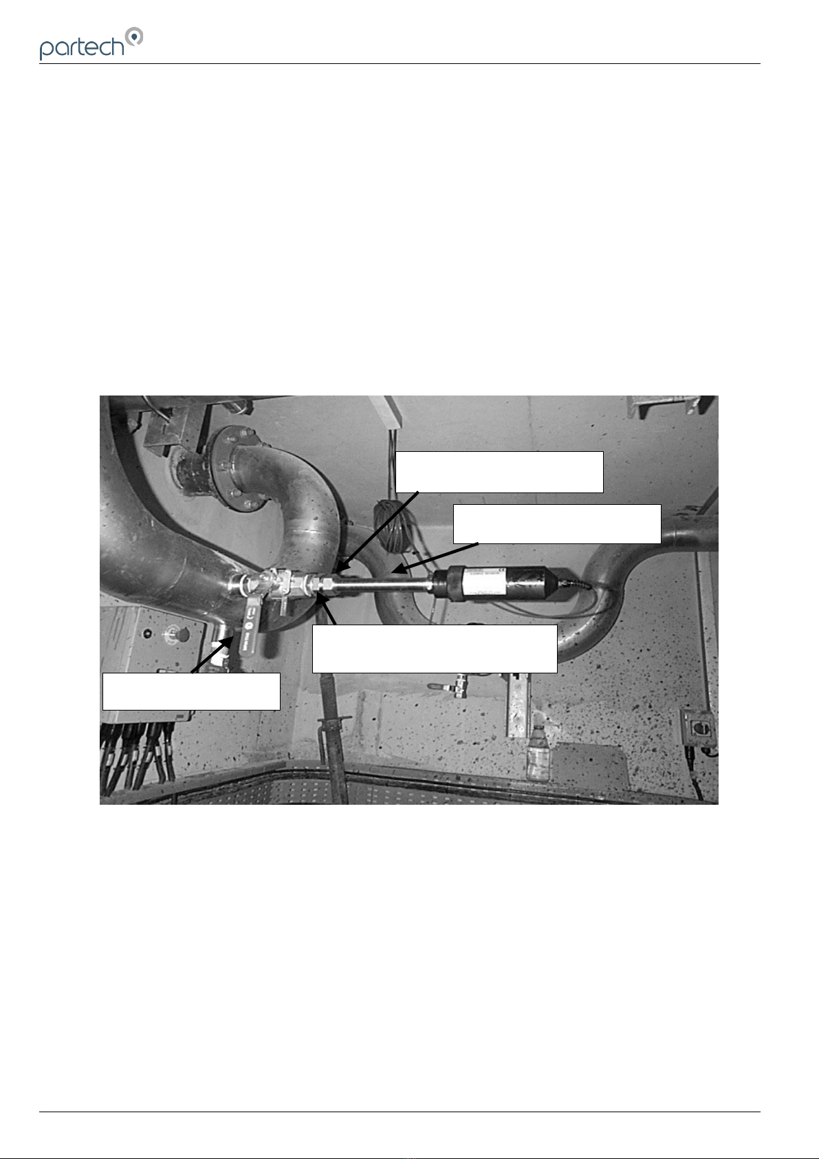
8 Application Example: Sludge Density Monitor............................................................................................................15
9 Spare Parts.................................................................................................................................................................16
9.1 Sensors............................................................................................................................................................16
9.2 Mounting Accessories......................................................................................................................................16
9.3 Miscellaneous..................................................................................................................................................16
10 Technical Support.....................................................................................................................................................17
10.1 Returning Equipment for Repair.....................................................................................................................17
11 Technical Specification (should be last section)........................................................................................................18
12 Appendix 1: Preparation of Formazin Turbidity Standard..........................................................................................19
12.1 Health & Safety Precautions..........................................................................................................................19
12.2 Method of Preparation...................................................................................................................................19
12.3 Preparation of Dilution’s.................................................................................................................................19
12.4 Calibration......................................................................................................................................................19
12.5 Storage Life....................................................................................................................................................19
13 Appendix 2: Fuller's Earth.........................................................................................................................................20
163790IM-Iss05 Issue Date 11/05/210 Page 3 of 22

IL55 and IL55BV2 Sensor Instruction Manual
1 Introduction
This manual covers the IL55 and IL55BV2 in-line sensors and should be read in conjunction with the manual for the
monitor being used.
Whilst every attempt has been made to ensure that the instructions are correct, common sense and good engineering
practice should always be used to adapt to specific site details. If you are in any doubt please contact Partech or your
local distributor for further information.
1.1 IL55/IL55BV2 Sensors
The IL55 and IL55/BV2 sensors are mounted onto a pipe to measure or detect the suspended solids, turbidity or
sludge density of the liquid flowing. The optical surface will be located such that it is flush with the inside wall of the
pipeline and perpendicular to the flow. The optical surface will be kept clean by the flow of the fluid, however a routine
cleaning regime will be required to ensure long term reliability.
The sensor uses 180° Back Scatter of infrared light to detect the presence of solids in the pipe, the sensor electronics
provides an output signal that is used by either the 8100/8200 or 7200 Monitor to infer the level of Sludge Density,
Suspended Solids or Turbidity.
The stainless steel and glass construction is resistant to corrosion and damage in most applications, if aggressive
chemicals or highly abrasive materials are present consult Partech before installation.
1.2 IL55BV2 Sensor
The IL55/BV2 differs from the IL55 in so much as that it is possible to remove it from the process without the need to
shut down or drain the line. This is due to the addition of a ball-valve mechanism enabling closure of the line and safe
and easy removal of the sensor.
1.3 7200 Monitor
The IL55/ IL55BV2 sensor is supplied with a 7200 Monitor for the measurement of suspended solids, turbidity and
sludge density. Please refer to the 7200 Monitor manual (167300IM) for full details about calibration and setup.
Page 4 of 22 163790IM-Iss05 Issue Date 11/05/2010
L55 and IL55BV2 Sensor Instruction Manual
2 Installation
A reliable accurate measurement from any instrument can only be achieved by correct installation of the measuring
device, in the case of turbidity and suspended solids this is particularly important. If you are in any doubt contact your
Partech representative for advice.
Below are some points that should be considered before starting to install the sensor, and again if the results obtained
are not meeting your requirements.
•Avoid areas of extreme flow or turbulence, air bubbles will disturb the readings.
•The pipe, to which the sensor is fitted, is required to be completely flooded at all times.
•There should be no rapid changes in pipe size near to the sensor installation point.
•Do not place the sensor in an area of no flow, as the suspended solids will settle out and not provide a
representative reading.
•Both the IL55 & IL55BV2 are removable from their mountings. It is therefore important to leave sufficient space
around the instrument so as to enable removal.
•The sensor must be monitoring in an area that is representative of the whole process to gain accurate results.
To allow a single technician to calibrate and maintain the system the sensor should be placed within sight of the
controller. Although cable runs of up to 100 metres are possible, operational problems may be encountered.
163790IM-Iss05 Issue Date 11/05/210 Page 5 of 22
MAXIMUM ±45 DEGREES
FROM HORIZONTAL
IL55 and IL55BV2 Sensor Instruction Manual
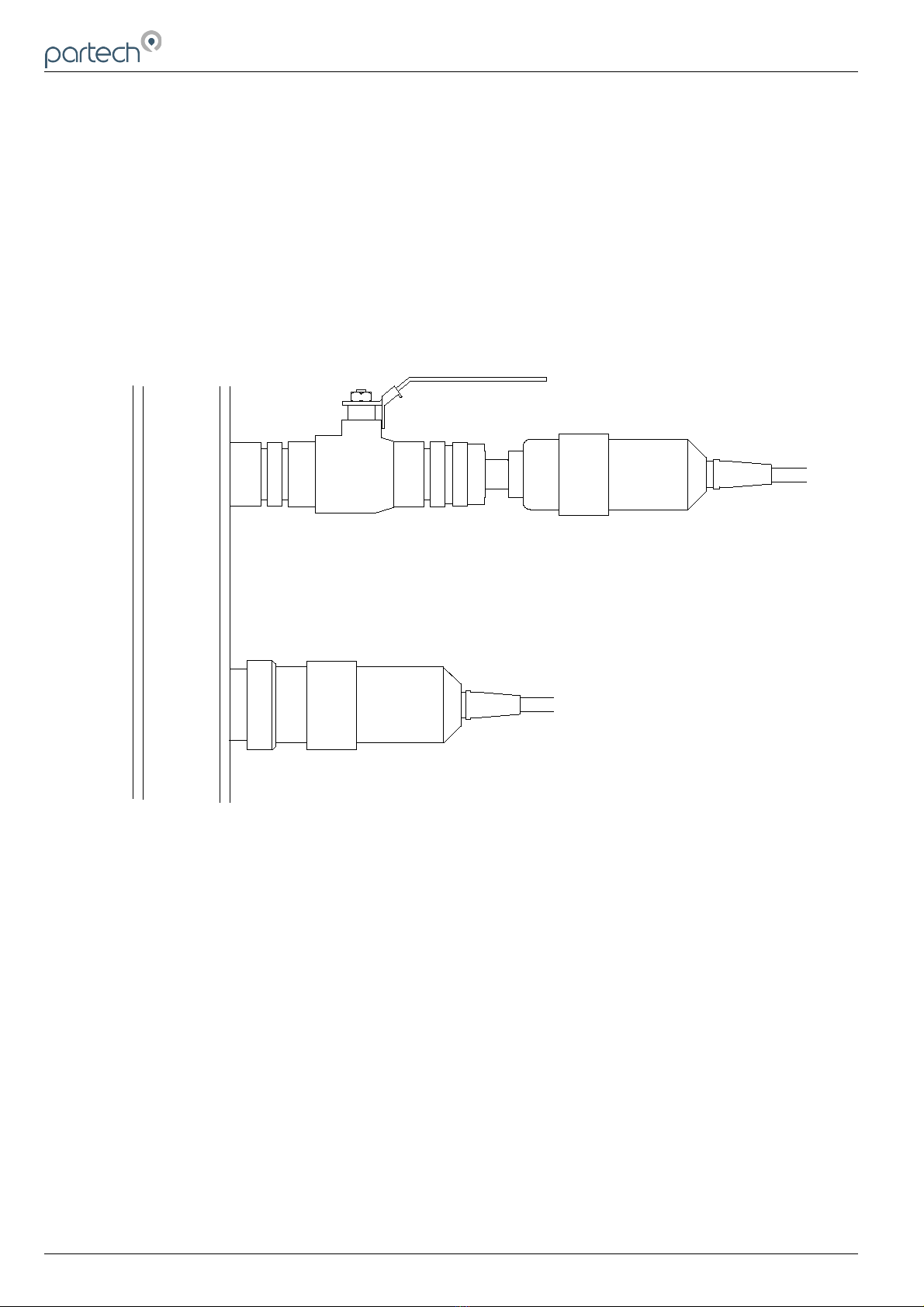
2.1 orizontal Pipelines
When mounting either an IL55 or IL55BV2 Sensor in to a horizontal pipeline, the sensor should be mounted in the
ideally horizontal or at an angle of up to 45o from the horizontal.
If the sensor is mounted vertically at the top of the pipe then air bubbles can cause unstable readings, if the sensor is
vertical at the bottom of the pipe the sensor could become prone to excessive fouling.
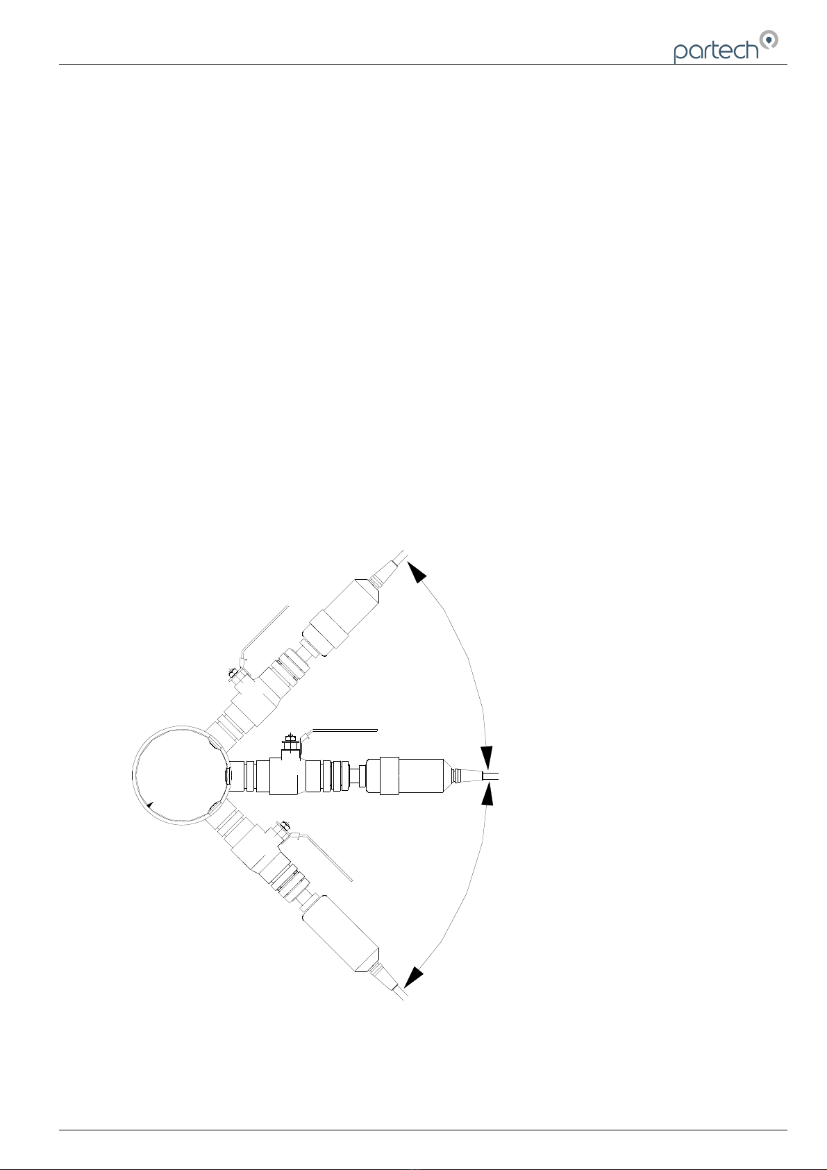
2.2 Vertical Pipelines
When mounting is to a vertical pipe, then the sensor should be mounted perpendicular to the pipe, in the horizontal
plane, as shown below:
2.3 Mounting Boss Installation
The IL55 sensor requires a mounting boss to facilitate its installation on the required pipe section. The boss is
available from Partech in several variations dependent upon customer requirements. The main options are: -
Direct Fitting: This boss has been designed to fit directly to the existing pipe section. Depending upon pipe material,
the boss will be welded (steel), or adhered (plastic) to the parent material. A hole to suit the inside diameter of the
boss will be required through the pipe wall, to allow entry of the sensor. Any welds should be of a minimum 5mm leg,
preferable the same size as the thickness of the pipe wall. All joints should be hydro-statically tested to at least 1.25
working pressure before putting the system back on-line. Competent personnel should only carry out this work. A safe
system of work should be exercised at all times e.g. all lines are drained and locked-off before starting, fire watch for
one-hour after welding.
Quick Fitting: With this option a special pipe section is supplied with the mounting boss attached. The section is
connected into the existing line using standard flange connections. Pipe sections are designed to meet customer
requirements.
With both methods care must be taken to ensure the boss is positioned as previously described in this manual. Failure
to do so will impair the performance and life of the sensor.
Page 6 of 22 163790IM-Iss05 Issue Date 11/05/2010

L55 and IL55BV2 Sensor Instruction Manual
3 Electrical Installation
For details of the electrical connections for the IL55 and IL55BV2 Sensors, refer to the 7200 Monitor instruction
manual.
3.1 Cable Routing
Care should be taken to ensure that the cable routing does not cause problems with the sensor measurement. Good
engineering practice should be followed with particular attention being paid to the following points:
•The sensor cable should be kept to the minimum length possible.
•Sufficient spare cable should be provided to allow complete and easy removal of the sensor from the process.
•Any spare cable should be safely stored.
•The sensor cable should be kept separate from the mains carrying cable.
163790IM-Iss05 Issue Date 11/05/210 Page 7 of 22
IL55 and IL55BV2 Sensor Instruction Manual
4 IL55BV2 Sensor
The IL55BV2 sensor is designed to allow the sensor to be withdrawn while the pipeline is in operation. The ball valve
allows the pipeline to be isolated while maintenance or calibration is carried out on the sensor.
WARNING: It must be noted that the IL55BV2 can only be used in applications that have a maximum line p essu e of
2 Ba o less.
Page 8 of 22 163790IM-Iss05 Issue Date 11/05/2010
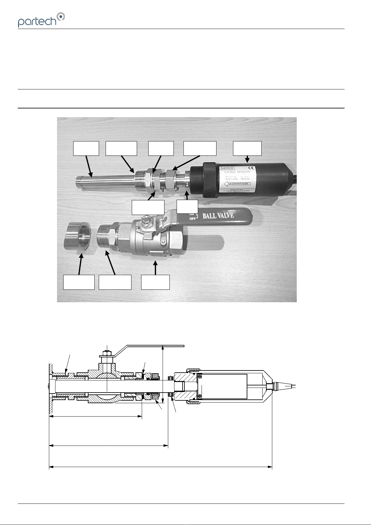
Mounting
Boss Ball Valve
Sensor
shaft
Ball valve
coupling nut
Dowty
Seal
Dowty seal
retaining nut
Sensor shaft
locking nut
collar
Sensor
body
Ball valve
coupling nut
120 mm
1 1/4" BSP internal thread
hole in pipe 42 dia
mounting boss
450.0 mm approx
sensor shaft in position
'L' dimension from
inside of tube
collar setting
dimension from
end of sensor
shaft to collar
dimension =
= 'L' + 45
connector male 1" BSP
hand tighten to lock
collar
Douwty seal
L55 and IL55BV2 Sensor Instruction Manual
4.1 Installation Procedure
Figure 4 below shows all major parts of the IL55/BV2. Installation of the sensor is simplified if the sensor is firstly split
into two parts, the ball valve section and the sensor shaft and body.
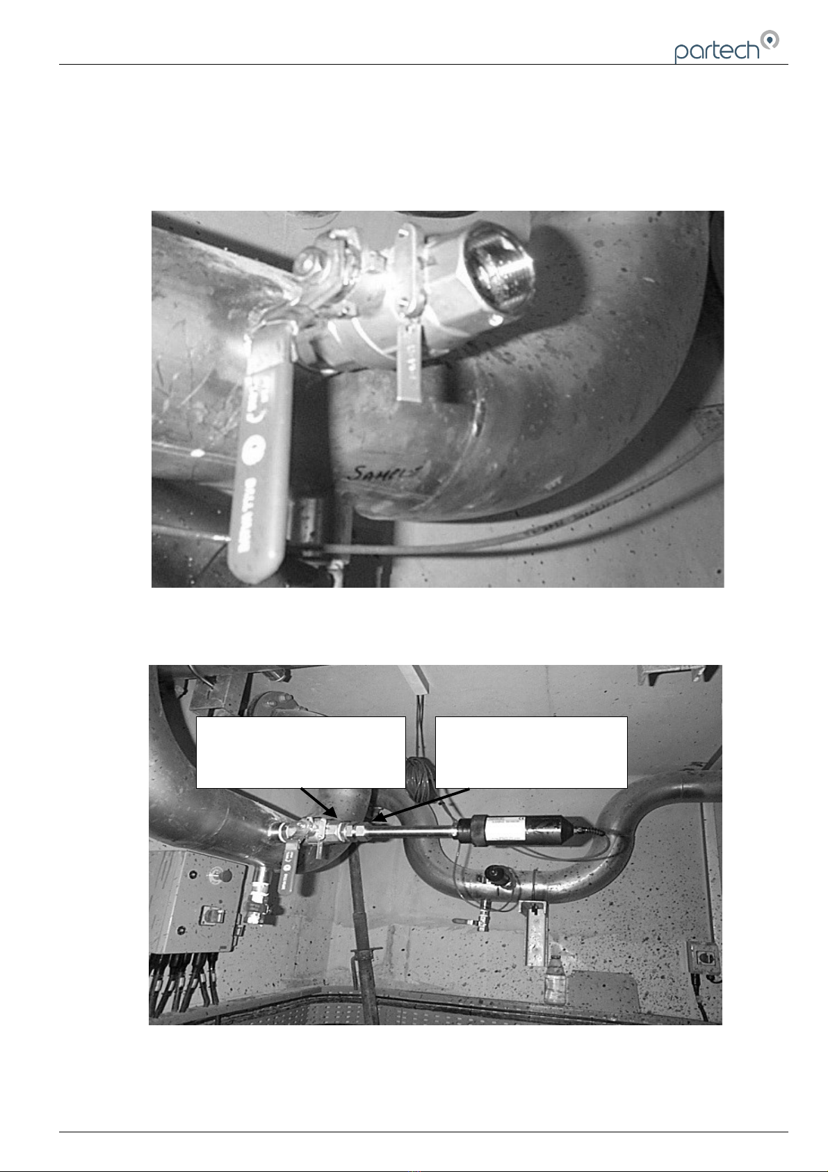
1. Once the mounting boss has been positioned and fastened to the pipeline, the ball valve mechanism via coupling
nut can be screwed into the mounting boss.
2. Insert the sensor shaft into the ball valve mechanism by screwing and tightening both coupling nut between ball
valve and sensor and Dowty seal retaining nut
163790IM-Iss05 Issue Date 11/05/210 Page 9 of 22
2, Insert shaft, tighten
ball valve coupling nut
and dowty seal
retaining nut
3, Open ball valve,
slide sensor into
pipe, position collar and
tighten shaft
locking nut
IL55 and IL55BV2 Sensor Instruction Manual
4.2 Sensor Removal
The IL55BV2 can be removed without the need for de-pressurising or draining of the line. This is achieved by the use
of the ball valve mechanism.
The removal of the IL55BV2 sensor is the reverse procedure of the installation process as outlined in the previous
section:
1. Loosen the shaft locking nut.
2. Ensure that there is sufficient free cable to allow sensor removal
3. Withdraw sensor to end stop.
4. Close ball valve.
5. Unscrew Dowty seal retaining nut and remove sensor.
6. Ensure that the optical surface is protected while out of the pipe.
Page 10 of 22 163790IM-Iss05 Issue Date 11/05/2010
1,Loosen shaft retaining nut
2, Withdraw sensor
3, Close ball valve
4, Unscrew dowty seal retaining
nut and remove sensor
This manual suits for next models
1
Table of contents
Other ParTech Accessories manuals


