Fbt MBT 1101 User manual
MBT 1101
A U D I O C O N T R A C T O R
FBT ELETTRONICA S.p.A. - Via Paolo Soprani, 1 - ZONA IND. SQUARTABUE - 62019 RECANATI (MC) - ITALY
ISTRUZIONI PER L’USO
INSTRUCTIONS FOR USE
Microphone stands UK
Postazioni da tavolo I
Mikrofonbasis D
Bases microphoniques F
MANUEL D'UTILISATION
GEBRAUCHSANLEITUNG
MBT 1101

i
INDICE DEI CONTENUTI
DESCRIZIONE 1
1.1 Riferimenti numerati 1
2. CONNESSIONI 1
3. CONFIGURAZIONE 2
3.1 Modalità MISCELAZIONE 2
3.2 Modalità INTERBLOCCO 3
3.3 Impostazione della modalità 4
4. USO
4
5. DATI TECNICI 4
TABLE OF CONTENTS
DESCRIPTION 1
1.1 Numbered references 1
2. CONNECTIONS 1
3. CONFIGURATION 2
3.1 MIXING mode 2
3.2 INTERLOCK mode 3
3.3 Setting the mode 4
4. USE
4
5. TECHNICAL DATA 4
1. DESCRIPTION 5
1.1 Reférences numerotées 5
2. CONNEXIONS 5
3. CONFIGURATION 6
3.1 Mode MELANGE 6
3.2 Mode INTERBLOCAGE 7
3.3 Configuration du mode 8
4. UTILISATION
8
5. DONNEES TECHNIQUES 8
SOMMAIRE
1. BESCHREIBUNG 5
1.1 Referensnummern 5
2. ANSCHLüSSE 5
3. KONFIGURATION 6
3.1 MISCH-Modus 6
3.2 INTERBLOCK-Modus 7
3.3 Moduseinstellung 8
4. GEBRäUCH 8
5. TECHNISCHE DATEN 8
INHALTSANGABE
1.
1.
I
UK
F
D

1
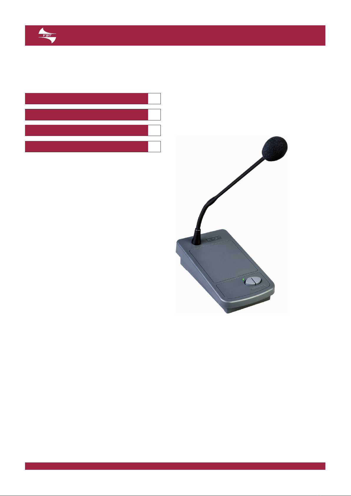
Le postazioni microfoniche preamplificate MBT 1101 sono
caratterizzate da un microfono elettrete. Sono in grado di funzionare
indifferentemente con alimentazione a 12 Vcc o 24 Vcc, adattandosi
così a qualsiasi esigenza applicativa.
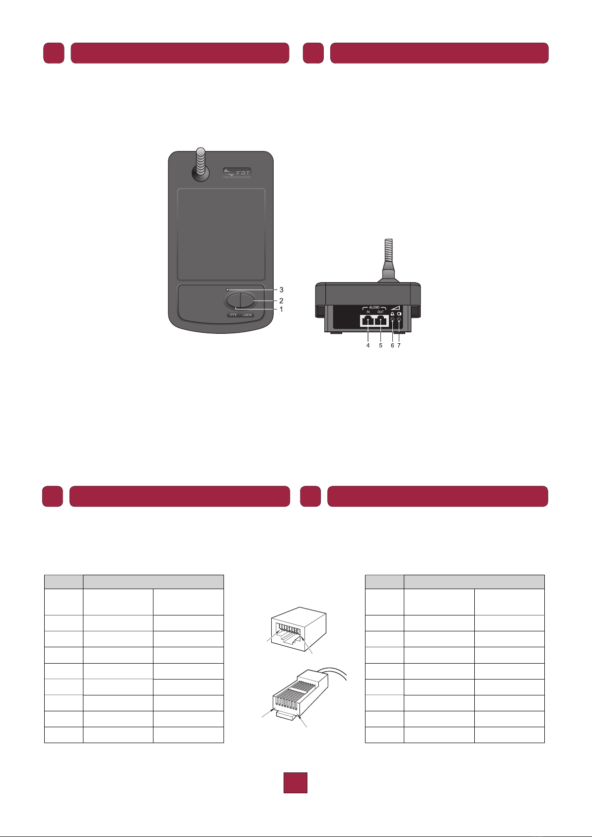
1.1 Riferimenti numerati
1. Pulsante di chiamata (a rilascio).
2. Tasto di chiamata (a ritenuta).
3. Led indicatore attivazione microfono.
4. Connettore ingresso audio.
5. Connettore uscita audio.
6. Regolazione livello segnale di preavviso (din-don).
7. Regolazione livello segnale microfonico.
I collegamenti delle postazioni sono effettuati tramite cavi STP cat.5
diretti (cioè non incrociati o ‘cross-cable’). Gli standard EIA/TIA
T568A e EIA/TIA T568B prevedono per tali cavi (e relativi connettori
tipo RJ45) le seguenti piedinature e colorazioni:
12345678
Pin 1
Pin 8
876 5 4321
Pin 8
Pin 1
T568A STANDARD
Pin Colore Colour
1bianco/verde white/green
2verde green
3bianco/arancio white/orange
4blu blue
5bianco/blu white/blue
6arancio orange
7bianco/marrone white/brown
8marrone brown
T568B STANDARD
Pin Colore Colour
1bianco/arancio white/orange
2arancio orange
3bianco/verde white/green
4blu blue
5bianco/blu white/blue
6verde green
7bianco/marrone white/brown
8marrone brown
The stations are connected by means of direct Cat. 5 STP cables
(no cross-cables). In accordance with EIA/TIA standard T568A and
EIA/TIA standard T568B, the pin-out for these cables (and their
RJ45 connectors) and the colour codes are:
The preamplified microphone stations MBT 1101 feature an electret
microphone. They can run on a 12 Vdc or a 24 Vdc power supply,
making them able to adapt to any application-related need.
1.1 Numbered references
1. Call button (hold-down type).
2. Call key (toggle type).
3. LED signalling activation of the microphone.
4. Audio input connector.
5. Audio output connector.
6. Warning signal level control (chime).
7. Microphone signal level control.
IUK
DESCRIZIONE DESCRIPTION
ICONNESSIONI UK CONNECTIONS
2
Importante!
Tutti i connettori devono essere di tipo RJ45 schermato.
Tutte le postazioni dispongono di una presa di ingresso AUDIO IN
e di una presa d’uscita AUDIO OUT. Nella tabella sottostante viene
elencata la piedinatura dei connettori.
Pin Audio IN Audio OUT
1Audio + Audio +
2Audio – Audio –
3GND GND
4Precedenza / Precedence IN Precedenza / Precedence OUT
5Non collegato / Not connected Non collegato / Not connected
6+Vcc +Vcc
7Seriale + / Serial + Seriale + / Serial +
8Seriale – / Serial – Seriale – / Serial –
Schermo / Shield GND GND
Le tipologie di collegamento dipendono dalla modalità di
funzionamento prescelta (fare riferimento ai paragrafi seguenti).
Le postazioni MBT 1101 possono funzionare in miscelazione tra
loro oppure ad interblocco con la gestione di due livelli di priorità.
È inoltre possibile attivare per ogni postazione un segnale di
preavviso (chime) con regolazione di volume posteriore. Il livello
del segnale microfonico è regolabile posteriormente.
NOTE:
Queste postazioni potranno effettuare solo chiamate generali.
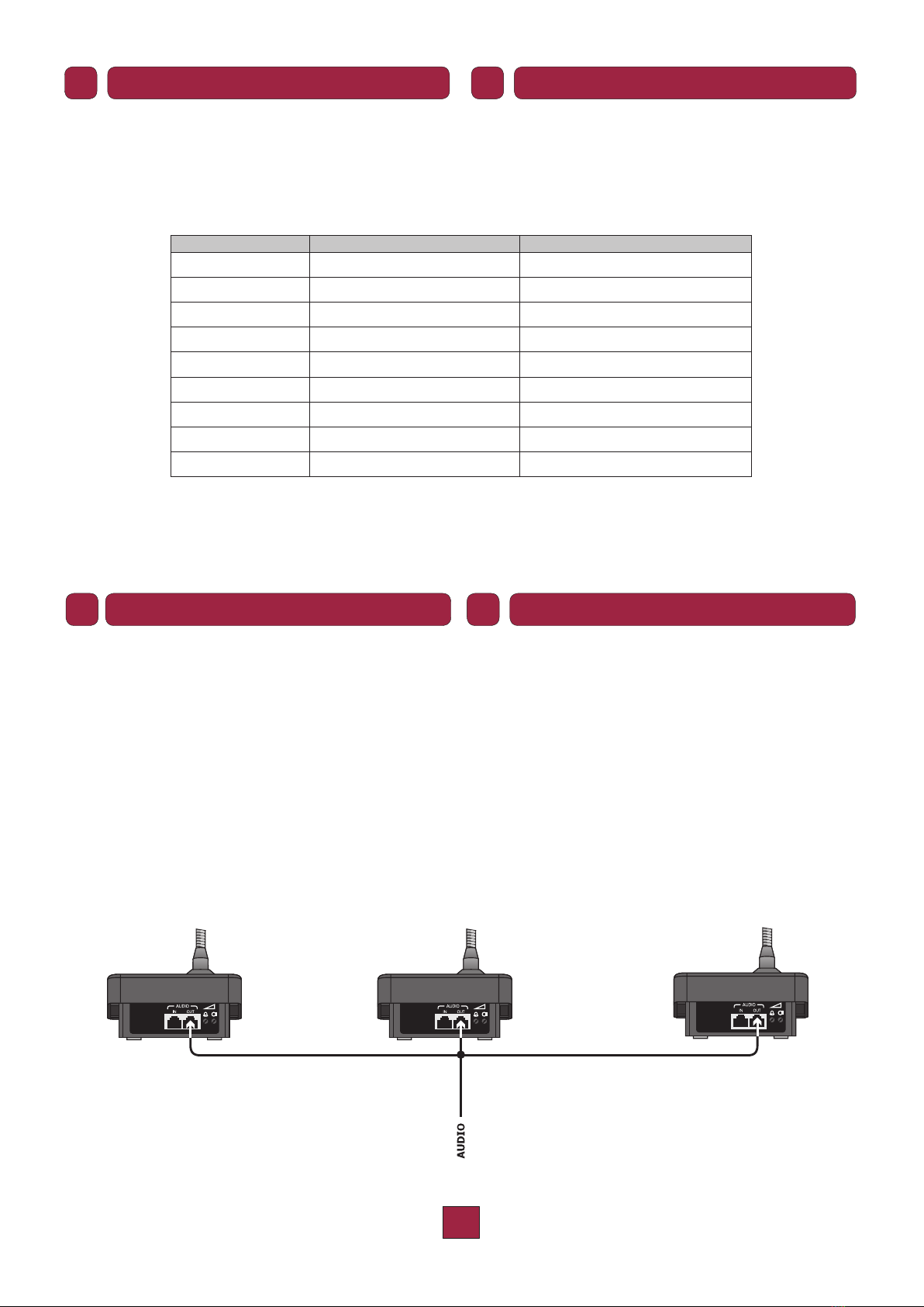
3.1 Modalità MISCELAZIONE
In questa modalità le postazioni possono effettuare liberamente
chiamate e/o attivazioni di allarmi. I collegamenti delle
linee AUDIO OUT provenienti da ogni postazione possono
essere parallelati ai morsetti dell’apparecchiatura di controllo
(collegamento a stella, fig. 3.1.1).
Fig. 3.1.1
Collegamento a stella
Star connection
Important!
All the connectors must be shielded RJ45 type.
Each station has an AUDIO IN input socket and an AUDIO OUT
output socket. The pin-outs of these connectors are listed below.
The types of connection depend on the manner of operation that
is chosen (see following sections).
The MBT 1101 stations can function in the mixing mode with one
another or interlocked with management of two priority levels. It is
also possible to activate a warning signal (chime) for each station,
with rear volume control. There is a level control for the microphone
signal on the rear panel.
NOTE:
These stations will only be able to make All-call calls.
3.1 MIXING mode
In this mode the stations can make calls and/or activate alarms
as required. The connections of the AUDIO OUT lines from each
station can be made in parallel to the terminals of the control
unit (star connection, Fig. 3.1.1).
IUK
CONNESSIONI CONNECTIONS
ICONFIGURAZIONE UK CONFIGURATION
3
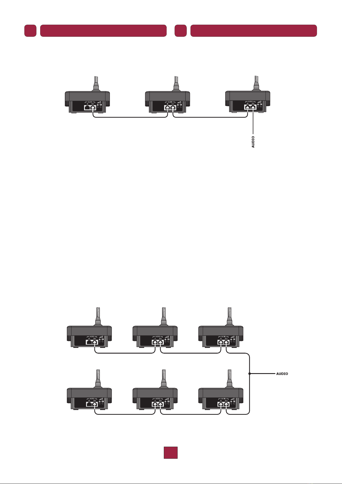
In alternativa, la linea AUDIO OUT di una postazione può essere
inserita nella presa AUDIO IN della postazione precedente
(collegamento in cascata o ‘daisy-chain’, figura 3.1.2).
Fig. 3.1.2
Collegamento a cascata
Daisy-chain connection
3.2 Modalità INTERBLOCCO
Le caratteristiche funzionali di questa modalità sono:
- solo una postazione per volta può essere attiva; durante
l’attivazione sulle altre postazioni il led (3) lampeggerà
per indicare la condizione di occupato; se la postazione
attiva è configurata in bassa priorità può essere disabilitata
dall’attivazione di una ad alta priorità.
- in caso di allarme attivato, la condizione sarà visualizzata
anche sulle altre postazioni; tutte le postazioni con il
corrispondente tasto di allarme abilitato potranno disattivare
l’allarme in corso.
- per avere un funzionamento coerente del sistema, è
necessario che tutte le postazioni siano programmate con la
modalità interblocco (scegliendo il livello di priorità per ogni
postazione) ed abbiano la stessa configurazione dei tasti di
allarme (scegliendo quali rendere attivi);
- le postazioni devono essere collegate in cascata tra loro
(‘daisy-chain’) con un massimo di due linee derivate a partire
dall’apparecchiatura di controllo (fig. 3.2.1).
Fig. 3.2.1
Modalità Interblocco
Interlock Mode
As an alternative, the AUDIO OUT line of a station can be
plugged into the AUDIO IN socket of the station preceding it
(cascade or daisy-chain connection, Fig. 3.1.2).
3.2 INTERLOCK mode
The functional features of this mode are the following:
- Only one station can be active at a time. While one station is
active, the LED (3) on the other stations will flash to indicate
a “busy” condition. If the active station is configured for low
priority, it can be disabled on activating a station with a higher
priority.
- When an alarm is activated, this condition will be displayed also
on the other stations. All the stations with the corresponding
alarm key enabled will be able to de-activate the current
alarm.
- For consistent operation of the system, it is necessary to
programme all the stations in the interlock mode (choosing
the required level of priority for each station) and for all the
alarm keys to have the same configuration (choosing which
to activate);
- The stations must be connected to one another in a daisy-
chain, with a maximum of two branched lines from the control
unit (Fig. 3.2.1).
IUK
CONFIGURAZIONE CONFIGURATION
4
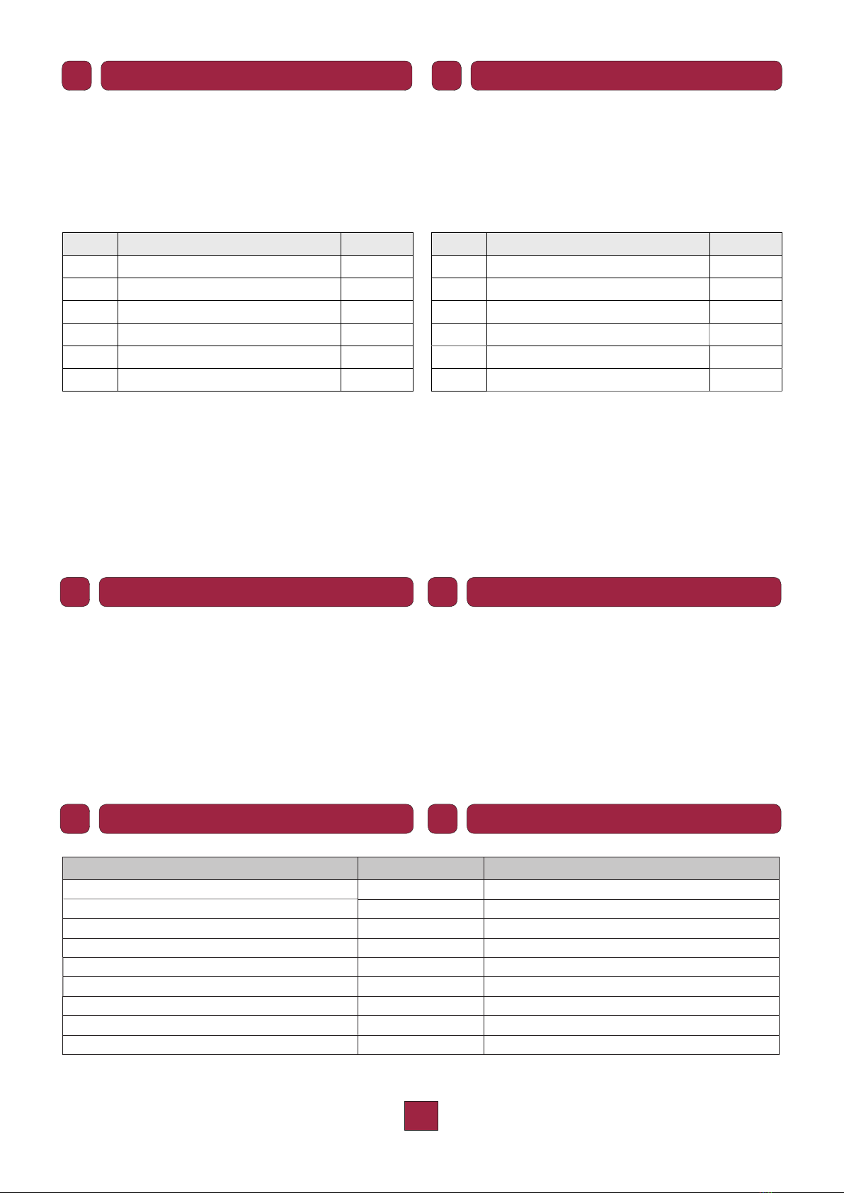
Impostazione della modalità
1. Premere contemporaneamente i tasti PTT e LOCK e quindi
alimentare la postazione inserendo il cavo alla presa AUDIO
OUT.
2. Il led (3) emetterà una sequenza di lampeggi ad indicare la
modalità correntemente impostata:
L(*) Modalità Din-Don
1Miscelazione -
2Miscelazione sì
3Interblocco con bassa priorità -
4Interblocco con bassa priorità sì
5Interblocco con alta priorità -
6Interblocco con alta priorità sì
(*) L = numero di lampeggi.
3. Per modificare la modalità di funzionamento della postazione,
premere il tasto LOCK una o più volte per avere il numero di
lampeggi del led relativo pari alla modalità prescelta; in modo
automatico si passerà dalla modalità 6 alla modalità 1.
4. Per uscire, salvando le impostazioni, premere il tasto PTT; la
postazione è immediatamente pronta per l’uso.
Premere, a scelta, il pulsante PTT od il tasto LOCK per attivare
la chiamata generale (con attivazione del segnale di preavviso, se
impostato) ed inviare il messaggio tramite il microfono: l’accensione
del led (3) confermerà l’attivazione microfonica.
Per terminare, rilasciare il pulsante PTT o ripremere il tasto LOCK:
la disattivazione microfonica sarà confermata dallo spegnimento
del led.
3.3 Setting the mode
1. Press the PTT and
LOCK keys at the same time, then power
up the station by plugging the cable into the AUDI
O OUT
socket.
2. The LED (3) will flash with a sequence indicating the mode that
has been set:
F(*) Mode Chime
1Mixing -
2Mixing yes
3Interlock with low priority -
4Interlock with low priority yes
5Interlock with high priority -
6Interlock with high priority yes
(*) F = Number of flashes
3. To change the operating mode of a station, press the LOCK
key once or more to see the number of flashes of the LED
corresponding to the chosen mode. The system will progress
from mode 6 to mode 1 automatically.
4. To exit saving the settings, press the PTT key. The station is
ready for immediate use.
Press the PTT button or the LOCK button depending on your choice,
to activate the All Call function (activating the chime, if set), and
use the microphone to send your message. The LED (3) will light
up to confirm activation of the microphone.
To terminate the call, release the PTT button or press the LOCK
button again. The LED will extinguish to confirm de-activation of
the microphone.
MODELLO MBT 1101 MODEL
Tipo di microfono elettrete / electret Microphone type
Alimentazione 12 V / 24 V Power supply
Assorbimento @12/24Vcc 140 mA / 50 mA Maximum Absorption @12/24Vdc 1
Risposta in frequenza 100 ÷ 15.000 Hz Frequency response
Livello audio (bilanciato) 1,2 Vrms Audio level (balanced)
Livello segnale di preavviso 0,8 Vpp Chime level
Limitatore di dinamica sì / yes Dynamics limiter
Dimensioni 116 x 60 x 200 mm Dimensions
Peso 0,5 kg Weight
(1) regolabile, adjustable.
IUK
CONFIGURAZIONE CONFIGURATION
IUSO UK USE
IDATI TECNICI UK TECHNICAL DATA
3.3
5
Les postes microphoniques préamplifiés MBT 1101 sont équipés
d’un microphone électrète. Ils fonctionnent aussi bien à 12 Vcc
qu’à 24 Vcc et s’adaptent ainsi à n’importe quelle exigence
d’application.
Reférences numerotées
1. Bouton d’appel (à relâchement).
2. Touche d’appel (à retenue).
3. DEL signalant l’activation du microphone.
4. Connecteur entrée audio.
5. Connecteur sortie audio.
6. Réglage du niveau du signal de préavis.
7. Réglage du niveau du signal microphonique.
Les connexions des postes sont réalisées à l’aide de câbles
STP cat. 5 directs (c’est-à-dire non croisés ou ‘cross-cable’). Les
standards EIA/TIA T568A et EIA/TIA T5668B prévoient pour
ces câbles (et les connecteurs correspondants de type RJ45) la
coloration et les brochages suivants:
12345678
Pin 1
Pin 8
8 7 6543 2 1
Pin 8
Pin 1
T568A
Broche
Pin Couleur Farben
1blanc/vert weiß/grün
2vert grün
3blanc/orange weiß/orange
4bleu blau
5blanc/bleu weiß/blau
6orange orange
7blanc/marron weiß/braun
8marron braun
T568B
Broche
Pin Couleur Farben
1bianco/arancio white/orange
2arancio orange
3bianco/verde white/green
4blu blue
5bianco/blu white/blue
6verde green
7bianco/marrone white/brown
8marrone brown
Die Anschlüsse der Sprechstellen werden mithilfe von direkten
STP-Kabeln Kat.5 (d. h. nicht mit Kreuzkabeln) hergestellt. Die EIA/
TIA T568A-Standards und EIA/TIA T568B sehen für diese Kabel
(und die entsprechenden Stecker des Typs RJ45) die folgenden
Pinstellungen und Farben vor:
Die vorverstärkten Tischsprechstellen MBT 1101 verfügen über
ein Elektretmikrofon. Sie können in gleicher Weise mit einer
Einspeisung mit 12 Vdc oder 24 Vdc betrieben werden und sind
daher für alle Anforderungen geeignet.
Referensnummern
1. Aufrufknopf (Druckknopf).
2. Aufruftaste (Haltetaste).
3. Led-Anzeige für Mikrofonaktivierung.
4. Stecker Audio-Eingang.
5. Stecker Audio-Ausgang.
6. Einstellung Ankündigungssignalstufe.
7. Einstellung Mikrofonsignalstufe.
FD
DESCRIPTION BESCHREIBUNG
ICONNEXIONS UK ANSCHLüSSE
1.1 1.1

6
Important!
Tous les connecteurs doivent être de type RJ45 blindé.
Tous les postes disposent d’une prise d’entrée AUDIO IN et d’une
prise de sortie AUDIO OUT. Les tableaux ci-après fournissent la
liste des brochages de ces connecteurs.
Broche / Pin Audio IN Audio OUT
1Audio + Audio +
2Audio – Audio –
3GND GND
4Priorité IN / Vorrang IN Priorité OUT / Vorrang OUT
5Pas connecté / Nicht angeschlossen Pas connecté / Nicht angeschlossen
6+Vcc +Vcc
7Série + / Seriell + Série + / Seriell +
8Série – / Seriell – Série – / Seriell –
Blindage / Geschmirt GND GND
Le type de connexion varie en fonction du mode de fonctionnement
choisi (voir les paragraphes suivants).
Les postes peuvent fonctionner en mélange entre eux ou bien par
interblocage avec la gestion de deux niveaux de priorité. Il est par
ailleurs possible d’activer un signal de préavis (chime) pour chaque
poste avec réglage du volume par l’arrière.
Le niveau du signal microphonique est réglable sur le panneau
arrière.
REMARQUE: ces postes pourront effectuer uniquement des appels
généraux
3.1 Mode MÉLANGE
Dans ce mode, les postes peuvent effectuer librement des
appels et/ou des activations d’alarmes. Les connexions des
lignes AUDIO OUT en provenance de chaque poste peuvent
être mises en parallèle sur les bornes de l’appareil de contrôle
(montage en étoile, fig. 3.1.1.).
Fig./Abb. 3.1.1
Montage en étoile
Sternanschluss
Wichtig!
Alle Stecker müssen geschirmte Stecker vom Typ RJ45 sein.
Alle Sprechstellen verfügen über eine Eingangsbuchse AUDIO IN
und eine Ausgangsbuchse AUDIO OUT. In den folgenden Tabellen
werden die Pinstellungen für diese Stecker aufgeführt.
Die Anschlussarten hängen von dem zuvor ausgewählten
Funktionsmodus ab (beachten Sie hierfür die nächsten
Abschnitte).
Die Sprechstellen können untereinander mischbar oder im
Interblockmodus mithilfe der Steuerung von zwei Vorrangsstufen
funktionieren. Außerdem besteht die Möglichkeit, für jede
Sprechstelle ein Ankündigungssignal (Chime) zu aktivieren,
dessen Lautstärkeregulierung sich an der Rückseite befindet. Die
Mikrofonsignalstufe kann an der Rückseite eingestellt werden.
ANMERKUNG: Mit diesen Sprechstellen können jedoch nur
allgemeine Rufe getätigt werden.
3.1 MISCH-Modus
In diesem Modus können an den Sprechstellen frei Rufe und/
oder die Aktivierung von Alarmen erfolgen. Die Anschlüsse der
Leitungen AUDIO OUT jeder Sprechstelle können parallel zu
den Klemmen des Kontrollgeräts (Sternanschluss, Abb. 3.1.1)
geschaltet werden.
FD
CONNEXIONS ANSCHLü SSE
ICONFIGURATION UK KONFIGURATION

7
3.2 Mode INTERBLOCAGE
En alternative la ligne AUDIO OUT d’un poste peut être insérée
dans la prise AUDIO IN du poste précédent (branchement en
cascade ou ‘daisy-chain’, fig. 3.1.2).
Fig. 3.1.2
Branchement en cascade
Kaskadenschaltung
Les caractéristiques de ce mode sont les suivantes:
- un seul poste peut être actif à la fois; pendant qu’un poste est
actif, la DEL (3) clignotera sur les autres postes afin d’indiquer
la condition “occupée”.
Si le poste actif est configuré en basse priorité, il peut
être désactivé par l’activation d’un poste à priorité élevée;
- en cas d’activation d’une alarme, la condition sera affichée
également sur les autres postes; tous les postes pourront
désactiver l’alarme en cours à l’aide de la touche d’alarme
correspondante;
- pour un fonctionnement cohérent du système, il faut que tous
les postes soient programmés avec le mode d’interblocage
(en sélectionnant le niveau de priorité de chaque poste) et
aient la même configuration pour les touches d’alarme (en
choisissant celles à activer);
- les postes doivent être branchés en cascade entre eux (‘daisy-
chain’) avec un maximum de deux lignes dérivées à partir de
l’appareil de contrôle (fig. 3.2.1).
Fig. 3.2.1
Mode Interblocage
Interblock-Modus
Alternativ kann die Leitung AUDIO OUT einer Sprechstelle
an die Buchse AUDIO IN der vorher installierten Sprechstelle
geschaltet werden (Abbildung 3.1.2).
3.2 INTERBLOCK-Modus
Die Funktionseigenschaften dieses Modus sind:
- Es kann jedes Mal nur eine Sprechstelle aktiviert werden;
während der Aktivierung blinkt die LED (3) an den anderen
Sprechstellen und zeigt damit den Belegtzustand an;
falls die aktive Sprechstelle mit einem niedrigen Vorrang
konfiguriert ist, kann ihre Freigabe durch die Aktivierung einer
Sprechstelle mit höherem Vorrang deaktiviert werden.
- Bei aktiviertem Alarm, wird dieser Zustand auch an den
anderen Sprechstellen angezeigt; alle Sprechstellen mit der
entsprechenden, freigegebenen Taste können den laufenden
Alarm deaktivieren.
-
Für einen problemlosen Betrieb des Systems ist es erforderlich,
dass alle Sprechstellen auf den Modus Interblock programmiert
werden (durch Auswahl der Vorrangeinstellungen für jede
Sprechstelle) und dieselbe Konfiguration der Alarmtasten
(durch Aktivierung der gewünschten Tasten) besitz
en.
- Die Sprechstellen müssen untereinander per Kaskaden-
schaltung (‘daisy-chain’) verbunden und mit maximal zwei
Abzweigleitungen an das Kontrollgerät angeschlossen
werden. Die Abb.3.2.1 zeigt ein entsprechendes Beispiel.
FD
CONFIGURATION KONFIGURATION

8
3.3 Configuration du mode
1. Appuyer simultanément sur les touches PTT et LOCK puis mettre
le poste sous tension en insérant le câble dans la prise AUDIO
OUT.
2. La DEL (3) émettra une série de clignotements afin d’indiquer
le mode actuellement sélectionné:
C(*) Ding-Dong Ding-Dong
1Mélange -
2Mélange oui
3Interblocage avec basse priorité -
4Interblocage avec basse priorité oui
5Interblocage avec haute priorité -
6Interblocage avec haute priorité oui
(*) C = nombre de clignotements.
3. Pour modifier le mode de fonctionnement du poste appuyer sur
la touche LOCK une ou plusieurs fois pour que le nombre de
clignotements de la diode correspondante soit égal au mode
sélectionné; le passage du mode 6 au mode 1 aura lieu en mode
automatique.
4. Pour quitter, en enregistrant les configurations, appuyer sur la
touche PTT; le poste est tout de suite prêt à l’usage.
Appuyer sur le bouton PTT ou sur la touche LOCK pour activer
l’appel général (avec activation du signal de préavis (chime), s’il
est configuré) puis envoyer le message à l’aide du microphone:
l’allumage de la DEL (3) confirmera l’activation microphonique.
Pour terminer, relâcher le bouton PTT ou appuyer de nouveau sur
la touche LOCK: la désactivation microphonique sera confirmée
par l’extinction de la DEL.
3.3 Moduseinstellung
1. Drücken Sie gleichzeitig die Tasten PTT und LOCK und speisen
Sie dann die Sprechstelle ein, indem Sie das Kabel an die Buchse
AUDIO OUT anschließen.
2. Die LED (3) zeigt daraufhin eine Blinksequenz an, die die zurzeit
eingestellte Modalität angibt.
B(*) Modus Ding-Dong
1Mischung -
2Mischung ja
3Interblock mit niedrigem Vorrang -
4Interblock mit niedrigem Vorrang ja
5Interblock mit hohem Vorrang -
6Interblock mit hohem Vorrang ja
(*) B = Anzahl der Blinksignale.
.
Für die änderung des Funktionsmodus der Sprechstelle drücken
Sie die Taste LOCK einmal oder mehrfach; hiermit wird die
Anzahl der Blinkanzeigen des ausgewählten Modus angezeigt;
im automatischen Modus wird vom Modus 6 zum Modus 1
gewechselt.
4. Wenn Sie das Menü verlassen wollen, speichern Sie die
Einstellungen und drücken Sie die Taste PTT; die Sprechstelle
ist daraufhin sofort betriebsbereit.
Drücken Sie je nach Wunsch den Knopf PTT oder die Taste
LOCK, um den allgemeinen Ruf zu aktivieren (mit Aktivierung des
Chime, falls eingestellt) und senden Sie die Meldung durch das
Mikrofon: Das Aufleuchten der LED (3) bestätigt die Aktivierung
des Mikrofons.
Um den Vorgang zu beenden, lassen Sie den Knopf PTT los
oder drücken Sie erneut die Taste LOCK: Die Deaktivierung des
Mikrofons wird durch die Abschaltung der LED bestätigt.
MODELE MBT 1101 MODELL
Type de microphone électréte / elektret Mikrofontyp
Alimentation 12 V / 24 V Speisung
Absorption à 12/24Vcc 140 mA / 50 mA Stromaufnahme 12/24V-VGS1
Reponse en fréquence 100 ÷ 15.000 Hz Frequenzgang
Niveau audio (équilibrée) 1,2 Vrms Audiostufe (symmetriert)
Niveau ding-dong 0,8 Vpp Stufe Ding-Dong
Limiteur de dynamique sì / yes Dynamikbegrenzer
Dimensiones 116 x 60 x 200 mm Abmessungen
Poids 0,5 kg Gewicht
(1) réglable, einstellbar.
3.
FD
CONFIGURATION KONFIGURATION
UTILISATION GEBRÄUCH
FD
DONNEES TECHNIQUES TECHNISCHE DATEN
FD

9

A U D I O C O N T R A C T O R
Code: 37781
Les information contenues dans ce manuel ont été soigneusement contrôlées; toutefois le constructeur n’est pas responsable
d’éventuelles inexactitudes. La FBT Elettronica S.p.A. s’octroie le droit de modifier les données techniques et l’aspect
esthètique de ses produits sans avis préalable.
Alle informationen in dieser Bedienungsanleitung wurden nach bestem Wissen und Gewissen zusammengestellt und
überprüft. Daher können sie als zuverlässig angesehen werden. Für eventuelle Fehler übernimmt FBT aber keine Haftung.
FBT Elettronica S.p.A. Behält sich das Recht auf Anderung der produkte und Spezifikationen vor.
Le informazioni contenute in questo manuale sono state scrupolosamente controllate; tuttavia FBT non si assume nessuna
responsabilità per eventuali inesattezze. La FBT Elettronica S.p.A. si riserva il diritto di modificare le caratteristiche tecniche
ed estetiche dei prodotti in qualsiasi momento e senza preavviso.
All information included in this operating manual have been scrupolously controlled; however FBT is not responsible for
eventual mistakes. FBT Elettronica S.p.A. has the right to amend products and specifications without notice.
Table of contents
Other Fbt Microphone manuals


