FCA US RAM 2500 2019 User manual

FiRST Edition
Printed in the U.S.A.
©2018 FCA US LLC. All Rights Reserved.
Ram is a registered trademark of FCA US LLC.
19DDDSL67-226-AA
DIESEL SUPPLEMENT
2019 2500/3500/4500/5500
RAM TRUCK
RAM TRUCK 2500/3500/4500/5500
2019
DID_3566548_19a_Ram_2500_3500_4500_5500_Diesel_EN_090618.indd 1 9/6/18 11:37 AM

VEHICLES SOLD IN CANADA
With respect to any Vehicles Sold in Canada, the name
FCA US LLC shall be deemed to be deleted and the name
FCA Canada Inc. used in substitution therefore.
DRIVING AND ALCOHOL
Drunken driving is one of the most frequent causes of
accidents.
Your driving ability can be seriously impaired with blood
alcohol levels far below the legal minimum. If you are
drinking, don’t drive. Ride with a designated non-
drinking driver, call a cab, a friend, or use public trans-
portation.
WARNING!
Driving after drinking can lead to an accident.
Your perceptions are less sharp, your reflexes are
slower, and your judgment is impaired when you
have been drinking. Never drink and then drive.
This manual illustrates and describes the operation of
features and equipment that are either standard or op-
tional on this vehicle. This manual may also include a
description of features and equipment that are no longer
available or were not ordered on this vehicle. Please
disregard any features and equipment described in this
manual that are not on this vehicle.
FCA US LLC reserves the right to make changes in design
and specifications, and/or make additions to or improve-
ments to its products without imposing any obligation
upon itself to install them on products previously manu-
factured.
Copyright © 2018 FCA US LLC
INSTALLATION OF RADIO TRANSMITTING
EQUIPMENT
Special design considerations are incorporated into this
vehicle’s electronic system to provide immunity to radio
frequency signals. Mobile two-way radios and telephone
equipment must be installed properly by trained person-
nel. The following must be observed during installation.
The positive power connection should be made directly
to the battery and fused as close to the battery as possible.
The negative power connection should be made to body
sheet metal adjacent to the negative battery connection.
This connection should not be fused.
Antennas for two-way radios should be mounted on the
roof or the rear area of the vehicle. Care should be used
in mounting antennas with magnet bases. Magnets may
affect the accuracy or operation of the compass on
vehicles so equipped.
The antenna cable should be as short as practical and
routed away from the vehicle wiring when possible. Use
only fully shielded coaxial cable.
Carefully match the antenna and cable to the radio to
ensure a low Standing Wave Ratio (SWR).
Mobile radio equipment with output power greater than
normal may require special precautions.
All installations should be checked for possible interfer-
ence between the communications equipment and the
vehicle’s electronic systems.
WARNING:
Operating, servicing and maintaining a
passenger vehicle or off-road highway
motor vehicle can expose you to chemicals
including engine exhaust, carbon monoxide,
phthalates, and lead, which are known to
the State of California to cause cancer and
birth defects or other reproductive harm.
To minimize exposure, avoid breathing
exhaust, do not idle the engine except as
necessary, service your vehicle in a
well-ventilated area and wear gloves or
wash your hands frequently when servicing
your vehicle. For more information go to
www.P65Warnings.ca.gov/passenger-vehicle.
DID_3566548_19a_Ram_2500_3500_4500_5500_Diesel_EN_090618.indd 2 9/6/18 11:37 AM

TABLE OF CONTENTS
SECTION PAGE
1INTRODUCTION ...................................................................3
2GETTING TO KNOW YOUR VEHICLE ....................................................5
3GETTING TO KNOW YOUR INSTRUMENT PANEL ...........................................9
4STARTINGANDOPERATING .........................................................29
5INCASEOFEMERGENCY ............................................................83
6SERVICING AND MAINTENANCE ......................................................91
7TECHNICAL SPECIFICATIONS ........................................................129
8INDEX..........................................................................139
1
2
3
4
5
6
7
8


A MESSAGE FROM FCA US LLC
FCA US LLC and Cummins welcome you as a Cummins
turbocharged diesel-powered truck owner. Your diesel
truck will sound, feel, drive, and operate differently from a
gasoline-powered truck. It is important that you read and
understand this manual.
Almost 100% of the heavy duty trucks in the United States
and Canada are diesel-powered because of the fuel
economy, rugged durability, and high torque which per-
mits pulling heavy loads. Cummins engines power well
over half of these trucks. Now this same technology and
proven performance is yours in your truck equipped with
the Cummins turbocharged diesel engine.
You may find that some of the starting, operating, and
maintenance procedures are different. However, they are
simple to follow and careful adherence to them will ensure
that you take full advantage of the features of this engine.
NOTE: Some aftermarket products may cause severe
engine/transmission and/or exhaust system damage. Your
vehicle’s Powertrain Control Systems can detect and store
information about vehicle modifications that increase
horsepower and torque output such as whether or not
performance-enhancing powertrain components, com-
monly referred to as downloaders, power boxes, or perfor-
mance chips have been used.
This information cannot be erased and will stay in the
system’s memory even if the modification is removed. This
information can be retrieved by FCA US LLC, and service
and repair facilities, when servicing your vehicle. This
information may be used to determine if repair will be
covered by the New Vehicle Limited Warranty.
There is a probability that the use of a “performance chip”
will prohibit the engine from starting. In this instance, the
vehicle will need to be serviced by a authorized dealer in
order to return the vehicle to its factory settings.
When it comes to service, remember that your authorized
dealer knows your vehicle best, has factory-trained techni-
cians and genuine MOPAR® parts, and cares about your
satisfaction.
4 INTRODUCTION

GETTING TO KNOW YOUR VEHICLE
CONTENTS
䡵REMOTE STARTING SYSTEM —
IF EQUIPPED ............................6
▫How To Use Remote Start ..................6
▫Remote Start Abort Message.................7
▫To Enter Remote Start Mode.................7
▫To Exit Remote Start Mode Without Driving The
Vehicle ................................7
▫To Exit Remote Start Mode And Drive
The Vehicle .............................8
▫Remote Start Comfort Systems — If Equipped ....8
2

REMOTE STARTING SYSTEM — IF EQUIPPED
This system uses the key fob to start the engine
conveniently from outside the vehicle while still
maintaining security. The system has a range of
approximately 300 ft (91 m).
NOTE:
•The vehicle must be equipped with an automatic trans-
mission to be equipped with Remote Start.
•The Remote Start system will wait for the “Wait To Start”
telltale to extinguish before cranking the engine. This
allows time for the intake heater to pre-heat the incom-
ing air, and is normal operation in cold weather. Refer to
“Wait To Start,” located in “Warning Lights And Mes-
sages” within “Getting To Know Your Instrument Panel”
for more information.
•Obstructions between the vehicle and the key fob may
reduce this range.
How To Use Remote Start
All of the following conditions must be met before the
engine will remote start:
•Transmission in PARK
•Doors closed
•Hood closed
•HAZARD switch off
•BRAKE switch inactive (brake pedal not pushed)
•Battery at an acceptable charge level
•PANIC button not pushed
•Fuel meets minimum requirement
•Water In Fuel Indicator Light is not illuminated
•Wait To Start Light is not illuminated
WARNING!
•Do not start or run an engine in a closed garage or
confined area. Exhaust gas contains Carbon Monox-
ide (CO) which is odorless and colorless. Carbon
(Continued)
6 GETTING TO KNOW YOUR VEHICLE

WARNING! (Continued)
Monoxide is poisonous and can cause serious injury
or death when inhaled.
•Keep Remote Keyless Entry key fobs away from
children. Operation of the Remote Start System,
windows, door locks or other controls could cause
serious injury or death.
Remote Start Abort Message
The following messages will display in the instrument
cluster display if the vehicle fails to remote start or exits
remote start prematurely:
•Remote Start Aborted - Door Open
•Remote Start Aborted - Hood Open
•Remote Start Aborted - Fuel Low
•Remote Start Aborted - System Fault
The instrument cluster display message stays active until
the ignition is placed in the ON/RUN position.
To Enter Remote Start Mode
Push and release the Remote Start button on the key fob
twice, within five seconds. The parking lights will flash
and the horn will chirp twice (if programmed). In cold
ambient temperature conditions, the diesel vehicle may
delay crank up to 30 seconds for the fuel and grid heater.
Once the vehicle has started, the engine will run for 15
minutes or 75 seconds in extreme cold and high elevation.
NOTE:
•The park lamps will turn on and remain on during
Remote Start mode.
•For security, power window and power sunroof opera-
tion (if equipped) are disabled when the vehicle is in the
Remote Start mode.
•The engine can be started two consecutive times (two
15-minute cycles) with the key fob. However, the igni-
tion switch must be cycled to the ON position before you
can repeat the start sequence for a third cycle.
To Exit Remote Start Mode Without Driving The
Vehicle
Push and release the Remote Start button one time or allow
the engine to run for the entire fifteen minute cycle.
NOTE: To avoid unintentional shut downs, the system
will disable the one time push of the Remote Start button
for two seconds after receiving a valid Remote Start
request.
2
GETTING TO KNOW YOUR VEHICLE 7

To Exit Remote Start Mode And Drive The Vehicle
To exit Remote Start Mode and drive the vehicle before the
end of the 15-minute cycle, push and release the unlock
button on the key fob to unlock the door and disarm the
vehicle security alarm System (if equipped). Then, prior to
the end of the 15-minute cycle, place the ignition to the
ON/RUN position.
NOTE: The ignition switch must be in the ON/RUN
position in order to drive the vehicle.
Remote Start Comfort Systems — If Equipped
When remote start is activated, the heated steering wheel,
and driver heated seat features will automatically turn on
in cold weather. In warm weather, the driver vented seat
feature will automatically turn on when the remote start is
activated. These features will stay on through the duration
of remote start or until the ignition switch is turned to the
ON/RUN position.
The Remote Start Comfort System can be activated and
deactivated through the instrument cluster display. For
more information on Remote Start Comfort System opera-
tion, refer to your Owner’s Manual.
8 GETTING TO KNOW YOUR VEHICLE

GETTING TO KNOW YOUR INSTRUMENT PANEL
CONTENTS
䡵INSTRUMENT CLUSTER ...................10
䡵INSTRUMENT CLUSTER DISPLAY ............15
▫Oil Life Reset ..........................18
▫Fuel Filter Life Reset .....................18
▫Diesel Particulate Filter (DPF) Messages .......19
▫Manual DPF Regeneration — Chassis Cab
Models Only (If Equipped) .................21
▫Instrument Cluster Display Messages .........24
▫Cold Ambient Derate Mode Messages .........24
▫Diesel Exhaust Fluid (DEF) Warning Messages . . .25
▫Diesel Exhaust Fluid (DEF) Fault Warning
Messages .............................26
䡵WARNING LIGHTS AND MESSAGES ..........27
▫Yellow Indicator Lights ...................27
▫Green Indicator Lights ....................28
3

INSTRUMENT CLUSTER
Base Instrument Cluster
10 GETTING TO KNOW YOUR INSTRUMENT PANEL

1. Tachometer
•Indicates the engine speed in revolutions per minute
(RPM x 1000).
2. Engine Coolant Temperature
•This gauge shows the engine coolant temperature. The
gauge pointer will likely show higher temperatures
when driving in hot weather, up mountain grades, or
in heavy stop and go traffic. If the red Warning Light
turns on while driving, safely bring the vehicle to a
stop, and turn off the engine. DO NOT operate the
vehicle until the cause is corrected.
WARNING!
A hot engine cooling system is dangerous. You or
others could be badly burned by steam or boiling
coolant. You may want to call an authorized dealer for
service if your vehicle overheats. If you decide to look
under the hood yourself, refer to “Dealer Service” in
“Servicing And Maintenance”. Follow the warnings
under the “Cooling System Pressure Cap” paragraph.
WARNING!
Driving with a hot engine cooling system could dam-
age your vehicle. If the temperature gauge reads “H”
pull over and stop the vehicle. Idle the vehicle with the
air conditioner turned off until the pointer drops back
into the normal range. If the pointer remains on the
“H”, turn the engine off immediately and call an
authorized dealer for service.
3. Instrument Cluster Display
•When the appropriate conditions exist, this display
shows the instrument cluster display messages. Refer
to “Instrument Cluster Display” in “Getting To Know
Your Instrument Panel” for further information.
4. Oil Pressure Gauge
•The pointer should always indicate some oil pressure
when the engine is running. A continuous high or low
reading under normal driving conditions may indicate
a lubrication system malfunction. Immediate service
should be obtained from an authorized dealer.
3
GETTING TO KNOW YOUR INSTRUMENT PANEL 11

5. Speedometer
•Indicates vehicle speed.
6. Fuel Gauge
•The pointer shows the level of fuel in the fuel tank
when the ignition switch is in the ON/RUN position.
•
The fuel pump symbol points to the side of the
vehicle where the fuel filler door is located.
7. DEF Gauge
•The DEF Gauge displays the actual level of Diesel
Exhaust Fluid in the DEF tank. Diesel Exhaust Fluid
(DEF) is required to maintain normal vehicle operation
and emissions compliance. If something is wrong with
the gauge, a DEF Warning Message or Malfunction
Indicator Light (MIL) will be displayed. More infor-
mation is available in the instrument cluster display
section under the heading of Diesel Exhaust Fluid
(DEF) Warning Messages.
NOTE:
•The gauge may take up to five seconds to update after
adding a gallon or more of Diesel Exhaust Fluid (DEF) to
the DEF tank. If you have a fault related to the DEF
system, the gauge may not update to the new level. See
your authorized dealer for service.
•The DEF gauge may also not immediately update after a
refill if the temperature of the DEF fluid is below 12F
(-11C). The DEF line heater will possibly warm up the
DEF fluid and allow the gauge to update after a period
of run time. Under very cold conditions, it is possible
that the gauge may not reflect the new fill level for
several drives.
•Outside temperature can affect DEF consumption. In
cold conditions, 12° F (-11° C) and below, the DEF gauge
needle can stay on a fixed position and may not move
for extended periods of time. This is a normal function of
the system.
12 GETTING TO KNOW YOUR INSTRUMENT PANEL

Premium Instrument Cluster
3
GETTING TO KNOW YOUR INSTRUMENT PANEL 13

1. Tachometer
•Indicates the engine speed in revolutions per minute
(RPM x 1000).
2. Instrument Cluster Display
•When the appropriate conditions exist, this display
shows the instrument cluster display messages. Refer
to “Instrument Cluster Display” in “Getting To Know
Your Instrument Panel” for further information.
3. Speedometer
•Indicates vehicle speed.
4. Fuel Gauge
•The pointer shows the level of fuel in the fuel tank
when the ignition switch is in the ON/RUN position.
•
The fuel pump symbol points to the side of the
vehicle where the fuel filler door is located.
5. DEF Gauge
•The DEF Gauge displays the actual level of Diesel
Exhaust Fluid in the DEF tank. Diesel Exhaust Fluid
(DEF) is required to maintain normal vehicle operation
and emissions compliance. If something is wrong with
the gauge, a DEF Warning Message or Malfunction
Indicator Light (MIL) will be displayed. More infor-
mation is available in the instrument cluster display
section under the heading of Diesel Exhaust Fluid
(DEF) Warning Messages.
WARNING!
A hot engine cooling system is dangerous. You or
others could be badly burned by steam or boiling
coolant. You may want to call an authorized dealer for
service if your vehicle overheats. If you decide to look
under the hood yourself, refer to “Dealer Service” in
“Servicing And Maintenance”. Follow the warnings
under the “Cooling System Pressure Cap” paragraph.
WARNING!
Driving with a hot engine cooling system could dam-
age your vehicle. If the temperature gauge reads “H”
pull over and stop the vehicle. Idle the vehicle with the
air conditioner turned off until the pointer drops back
into the normal range. If the pointer remains on the
“H”, turn the engine off immediately and call an
authorized dealer for service.
14 GETTING TO KNOW YOUR INSTRUMENT PANEL

NOTE:
•The DEF tank on these vehicles is designed with a
large amount of full reserve. So the level sensor will
indicate a full reading even before the tank is com-
pletely full. To put it another way, there’s additional
storage capacity in the tank above the Full mark that’s
not represented in the gauge. You may not see any
movement in the reading – even after driving up to
2,000 miles in some cases.
•The gauge may take up to five seconds to update after
adding a gallon or more of Diesel Exhaust Fluid (DEF)
to the DEF tank. If you have a fault related to the DEF
system, the gauge may not update to the new level. See
your authorized dealer for service.
•The DEF gauge may also not immediately update after
a refill if the temperature of the DEF fluid is below 12F
(-11C). The DEF line heater will possibly warm up the
DEF fluid and allow the gauge to update after a period
of run time. Under very cold conditions, it is possible
that the gauge may not reflect the new fill level for
several drives.
•Outside temperature can affect DEF consumption. In
cold conditions, 12° F (-11° C) and below, the DEF
gauge needle can stay on a fixed position and may not
move for extended periods of time. This is a normal
function of the system.
INSTRUMENT CLUSTER DISPLAY
Instrument Cluster Display — Base
1 – Instrument Cluster Display Controls
2 – Instrument Cluster Display Screen
3
GETTING TO KNOW YOUR INSTRUMENT PANEL 15

The instrument cluster display features a driver-interactive
display that is located in the instrument cluster.
This system allows the driver to select a variety of useful
information by pushing the switches mounted on the
steering wheel. The instrument cluster display may consist
of the following:
•Digital Speedometer
•Vehicle Info
•Fuel Economy Info
•Trip A
•Trip B
•Trailer Tow
•Audio
•Stored Messages
•Screen Setup
•Vehicle Settings (Not Equipped with a Uconnect 3 With
5-inch Display, Uconnect 4C/4C NAV With 8.4-inch
Display or Uconnect 4C NAV With 12-inch Display
radio)
•Settings
•Turn Menu Off
Instrument Cluster Display — Premium
1 – Instrument Cluster Display Controls
2 – Instrument Cluster Display Screen
16 GETTING TO KNOW YOUR INSTRUMENT PANEL
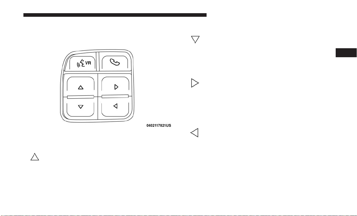
The system allows the driver to select information by
pushing the following buttons mounted on the steering
wheel:
•Up Arrow Button
Push and release the up arrow button to scroll
upward through the main menu and submenus
(Fuel Economy, Trip A, Trip B, Audio, Stored
Messages, Screen Set Up).
•Down Arrow Button
Push and release the down arrow button to scroll
downward through the main menu and sub-
menus (Fuel Economy, Trip A, Trip B, Audio,
Stored Messages, Screen Set Up).
•Right Arrow Button
Push and release the right arrow button to
access/select the information screens or sub-
menu screens of a main menu item. Push and
hold the right arrow button for two seconds to
reset displayed/selected features that can be reset.
•Left Arrow Button
Push the left arrow button to access/select the
information screens or submenu screens of a
main menu item or to return to the main menu
from an info screen or submenu item.
Steering Wheel Buttons
3
GETTING TO KNOW YOUR INSTRUMENT PANEL 17

Oil Life Reset
Your vehicle is equipped with an engine oil change indi-
cator system. The “Oil Change Required” message will
display in the instrument cluster display after a single
chime has sounded, to indicate the next scheduled oil
change interval.
NOTE: Use the steering wheel instrument cluster display
controls for the following procedure.
Oil Life Reset Procedure
1. Without pushing the brake pedal, push the ENGINE
START/STOP button and place the ignition to the
ON/RUN position (do not start the engine).
2. Push and release the down arrow button to scroll
downward through the main menu to “Vehicle Info.”
3. Push and release the right arrow button to access the
”Vehicle Info” screen, then scroll up or down to select
“Oil Life.”
4. Push and hold the right arrow button to select “Reset”.
5. Push and release the down arrow button to select “Yes,”
then push and release the right arrow button to reset the
Oil Life to 100%.
6. Push and release the up arrow button to exit the
instrument cluster display screen.
Secondary Method Of Resetting Engine Oil Life
1. Without pressing the brake pedal, push the ENGINE
START/STOP button and place the ignition to the
ON/RUN position (do not start the engine).
2. Fully press the accelerator pedal, slowly, three times
within ten seconds.
3. Without pushing the brake pedal, push the ENGINE
START/STOP button once to return the ignition to the
OFF/LOCK position.
NOTE: If the indicator message illuminates when you start
the vehicle, the oil change indicator system did not reset. If
necessary, repeat this procedure.
Fuel Filter Life Reset
The cluster will display the “Service Fuel Filter” message
when the fuel filter maintenance life is less than 5%. To
check the remaining fuel filter life, go to the “Fuel Filter
Life” screen in the “Vehicle Info” menu. When this message
appears, dealers should replace the fuel filter.
NOTE: Use the steering wheel button controls for the
following procedure.
18 GETTING TO KNOW YOUR INSTRUMENT PANEL
This manual suits for next models
3
Table of contents
Other FCA US Truck manuals


 Operator's manual")


