FCI SmartFlush User manual

SmartFlush Toilet Wall Mount
User’s Manual
Thank you for choosing the automatic urinal flusher. Please read the instruction carefully before installation. This manual is for your
reference only.

Features
Hands free sensor operation.
Adjustable control stop for water flow adjustment
Manual push button for flushing.
Adjustable sensing distance
Specifications
Power
6V
(2 x Alkaline AA)
AC
110
-
240V 50
–
60 Hz
Water Pressure
0.3
–
0.8 MPa
Water Temperature
0.1
–
50
o
C
Water Flow
Volume
9
–
12 L (Single flush @ 0.24 MPa)
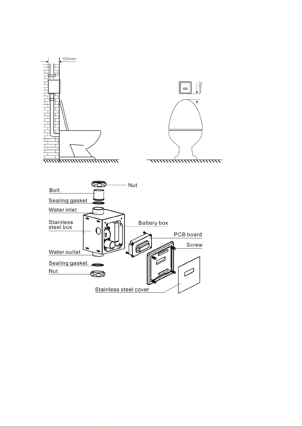
Construction / Installation Diagram
Plumbing installation must be in accordance with applicable codes and regulations.
Water supply lines must be sized to provide an adequate volume of water for each
fixture. Flush all waterlines prior to operation.
Prior to installing your Flush Valve, install the items listed below:
Tolilet fixture
Drain line
Water supply line
The supply piping to these devices must be securely anchored to the building structure
to prevent the installed device moving during use. Prevent marring to the exposed
surface during installation. IMPORTANT: Purge all air from the supply lines before
connecting flush valve to the bowl.
To prevent valve malfunction, do not install a handrail or any other object within the
detection range of the sensor. Do not install the flush valve where sensor faces a mirror,
stainless steel wall, other highly reflective surfaces or another infrared sensor.
Determine the installation location of the studs and water supply pipe relative to the
position of the toilet.
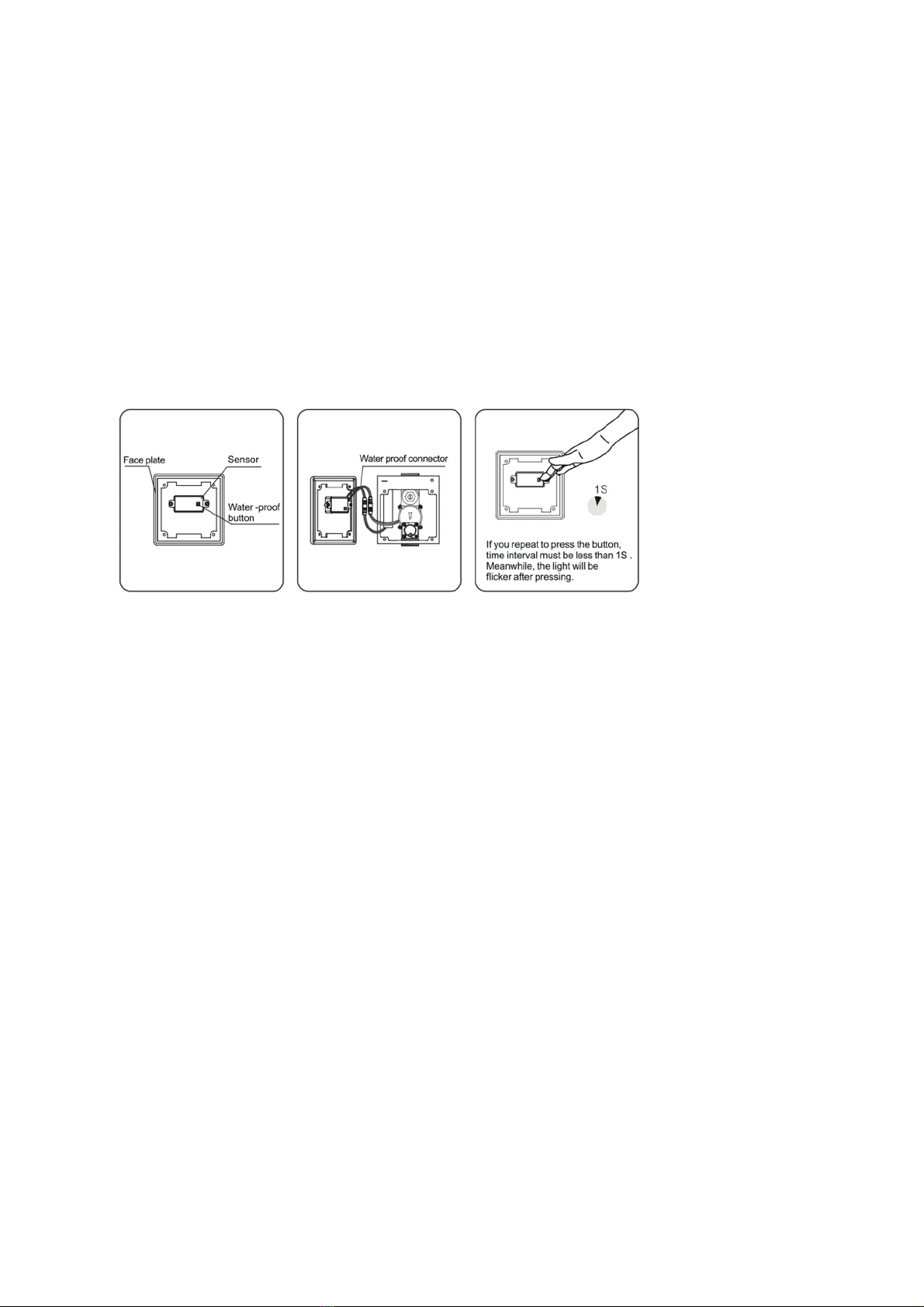
Detection / Activation
No manual adjustments are required for most settings. Default beam’s effective range is
65 – 70 cm. The factory setting should be satisfactory for most installations.
Range Adjustment
If the range is too short or too long, it can be adjusted.
1. Using a phillips screw driver remove the stainless steel cover plate by
unscrewing the screw from the bottom of the plate.
2. Ensure both cables are connected.
3. Press the black push button three time (x3) unitl the sensor red LED flashes.
4. Place a target sensor view at a desired distance for 30 seconds. The LED will
stay on for 5 seconds before flashing twice indicating distance set.
Water Flow Time Adjustment
Default water flow delivery is 8 seconds.
1. Press te black push button 5 times (x5) unit the red LED stays on. The valve will
open, flushing once to indicate ready for timing adjustment.
2. Within 10 seconds, press the black push once for 6 seconds delivery, push twice
for 8 seconds, 3 times for 10 seconds delivery, 4 times for 12 seonds delivery.
Solenoid Valve Maintenance

1. Shutfoff all water lines.
2. Remove the stainless steel front cover.
3. Disconnect the sensor & power cables.
4. Using a phillips screw driver remove the black plastic front cover.
5. Remove the four solenoid valve screws (black body).
6. Gently pull out the following solenoid cover through diaphgram bracket.
7. Clean the valve seat using a dampened soft cloth with diluted dishwashing
detergent and dry it with another soft cloth.
8. When completed, assemble back the soelnodi valve.
Flow Rate Adjustment
Locate the control stop (stop valve) & with a flat head screw driver adjust (counter
clockwise) the stop valve to desired flow rate.
Battery Replacement
Replace battery when RED LED indicator flashes rapidly or when flusher stops
functioning.
i. Turnoff the stop valve.
ii. Disconnect the battery box from the sensor.
iii. Remove the battery holder
iv. Using a Philips screw driver remove the battery cover and the batteries.
v. Replace 4 AA batteries
vi. Place back the battery cover and fasten the four Phillip screws to secure
the cover.
vii. Connect the battery holder to the sensor and place the battery holder
inside the junction box.
viii. Place the black plastic junction cover & fasten cover onto the junction box.

Troubleshooting
1. Valve does not flush.
i. The main valve in water supply line or the control stop is shut off. Open
the main valve or the stop valve.
ii. The connectors are not connected. Connect the wires.
iii. The surface of the sensor is dirty. Clean surface with soft cloth.
iv. There is a reflective surface in front of the sensor. Remove the reflective
surface from the front of the sensor.
v. The sensor or the solenoid is not functioning. Contact distributor for
possible part replacement.
vi. Small holes in the diaphgram is clogged. Clean the small hole in the
diaphgram using a small needle.
2. Valve will not shutoff
i. Plunger damage. Contact distributor for possible part replacement.
3. Water delivery is too small / too large
i. Stop valve flow rate not adjusted properly. Adjust the water discharge rate
by the turning the stop valve clockwise or counterclockwise.
4. Red LED flashing when user steps in sensor range. Batteries are low.
i. Replace batteries.
Care & Cleaning
IMPORTANT! Do not scratch the sensor or faceplate when cleaning. Avoid using any
cleaning materials that may scratch the surface.
Never use polishing powder, detergent that includes coarse particles, thinners,
benzene, acids, alkaline detergents, or nylon scrub brushes.
To safely clean the surface, wipe it using a dampened soft cloth with diluted
dishwashing detergent and dry it with another soft cloth. If this does not adequately
clean the surface, wipe the area with a neutral detergent and wet cloth.
Table of contents
Popular Toilet manuals by other brands


Hornbach
Hornbach 10293977 Assembly instructions

Kohler
Kohler Reve Comfort Height K-3797-0 Installation and care guide

Toto
Toto MS914R Series installation manual

Woodbridge
Woodbridge B0970S installation manual

Tecma
Tecma EasyFit Eco Owners and installation manual

DURAVIT
DURAVIT DuraSystem WD1004 000 000 Mounting instructions