FCS Multilog LX2 Manual

User Guide: Multilog LX2
Installation and Setup
This manual contains important safety and operating information.
Please read, understand, and follow the instructions in the manual and
also any documents shipped with the device.

MAN-146-0006-A
TABLE OF CONTENTS
1. Introduction .......................................................................................................................1
1.1. Documentation and Support of Product .................................................................1
1.2. Operating Temperature ............................................................................................1
1.3. Viewing Data...............................................................................................................2
2. Overview ............................................................................................................................3
2.1. Device Overview.........................................................................................................3
2.1.1. Physical Features & Connector Identification ..................................................3
2.2. External Battery (Option)...........................................................................................4
2.3. Communications Links (for programming and data download)............................4
2.4. Software Tool (for logger programming and tests) ................................................5
2.4.1. IDT (PC version)...................................................................................................5
2.5. Logger Operation.......................................................................................................5
2.6. Enhanced Logging (options)......................................................................................6
2.7. Server Integration –Storing and Viewing Data .......................................................7
2.7.1. DataGate Server / Data Viewing Portals ...........................................................7
2.8. Installation Accessories .............................................................................................8
3. Activating the Logger and Communications Link ...........................................................9
3.1. Logger Activation Process (for first-time use)..........................................................9
3.2. IDT - used with a PC. ..................................................................................................9
4. Interfaces and Sensor Types (Summary).......................................................................10
5. Installation .......................................................................................................................12
5.1. Summary of Installation Steps................................................................................12
5.2. Logger .......................................................................................................................13
5.2.1. Wall-mounting ..................................................................................................13
5.2.2. Locating in Plastic-lidded Chambers...............................................................14
5.3. Pressure Sensor Inputs ...........................................................................................16
5.3.1. Re-zero Facility (for pressure relative to local atmosphere) .........................16
5.3.2. Pressure Sensor (Internal) ...............................................................................16
5.3.3. Pressure Sensor (External)...............................................................................17
5.4. Flow Sensor Input (meter pulse collection) ...........................................................19
5.4.1. Via a Glanded Y-cable.......................................................................................19
5.4.2. Explanation of Flow Channels & Input Signals...............................................20
5.4.3. Via a Glanded Cable (open-ended)..................................................................21
5.4.4. Via a Logger 4-pin Bulkhead Connector .........................................................22

5.5. Connecting Unterminated Cable Wires to Equipment .........................................23
5.6. Status Input ..............................................................................................................23
5.7. External Battery .......................................................................................................23
5.7.1. Via a Captive Cable (with connector)...............................................................23
5.7.2. Via a Shared Connector / Cable.......................................................................24
5.8. SonicSens 2...............................................................................................................24
5.8.1. Via an Exclusive-use Connector.......................................................................24
5.8.2. Via a Shared-use Connector ............................................................................24
5.9. Temperature Input (RTD - PT100)...........................................................................24
5.10. LNS Input (Leak-Noise Sensor / Hydrophone) ...................................................25
5.11. Voltage Input (0-1V, 0-10V) ..................................................................................27
5.12. Current Input (4-20mA)........................................................................................27
5.13. Serial Input (SDI-12)..............................................................................................27
5.14. Serial Input (RS485 / MODBUS)...........................................................................28
5.15. Antenna Input (GPS Satellite) ..............................................................................30
5.16. Antenna (Cellular communications) ...................................................................31
6. Troubleshooting ..............................................................................................................35
7. Maintenance, Service and Repair...................................................................................36
7.1. Cleaning ....................................................................................................................36
7.2. Replaceable Parts ....................................................................................................36
7.3. Return of Product for Service or Repair.................................................................36
8. Appendix 1: Communicating to logger via SMS............................................................37

1
MAN-146-0006-A
1. INTRODUCTION
The “Multilog LX2” is a multi-purpose data logger device. Several models are available.
Please contact your sales representative for help with selection of an appropriate model
for your application.
HWM also provides a software tool for logger setup, known as “IDT”.
1.1. DOCUMENTATION AND SUPPORT OF PRODUCT
This user-guide covers the following models:
Model Number
Device Description
LX/*/*/*
Multilog LX2 logger device.
This user-guide should be read in conjunction with:
Document Number
Document Description
MAN-148-0002
Safety Warnings and Approvals Information
(for Multilog LX2).
MAN-130-0017
IDT (PC version) user-guide.
This user-guide provides details of the logger operation and how to install the product.
Also refer to any user-guides or datasheets for sensors that are being used with the
logger.
Read the relevant parts of the IDT user-guide for guidance on how to confirm settings or
modify the set-up your logger. This includes:
•Details of setup of sensor channels and making recordings of the data.
•Logger settings for the delivery of measurement data to a server.
•Logger setup for additional messaging features, such as alarms.
Note: The system periodically has new features and changes released, thus you may
observe slight changes from the diagrams and features shown in this manual.
Installed features and functionality can vary from device to device, therefore
always refer to the menus and screens of any setup tool to determine which
features are available on your logger device.
HWM provides support of logger devices by means of our customer support webpages:
https://www.hwmglobal.com/help-and-downloads/
Should you have any questions that are not covered by this manual or online help,
please contact the HWM Technical Support team on +44 (0) 1633 489479,
or email cservice@hwm-water.com
1.2. OPERATING TEMPERATURE
Refer to the logger Datasheet or your sales representative for guidance on the storage
and operating temperature range of the device. Ensure the unit is within the operating
temperature range prior to installation or setup.

2
MAN-146-0006-A
1.3. VIEWING DATA
To view logger data remotely, a viewing tool (website) is used. Various websites are
available. Each website presents data associated with logger installation sites. The
choice of website will depend on the type of sensors used and their application.
Data from your logger can also be viewed locally using IDT during a site visit.
Refer to the training materials available for your viewing tool and also the IDT user-
guide for further information.
3
MAN-146-0006-A
2. OVERVIEW
2.1. DEVICE OVERVIEW
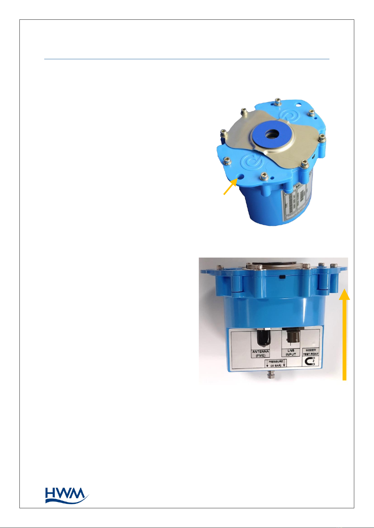
2.1.1. PHYSICAL FEATURES &CONNECTOR IDENTIFICATION
The Multilog LX2 logger family is flexible in
design and can be built to suit a variety of uses.
An example is shown in Figure 1and Figure 2.
The top face of the logger includes an infrared
communications window. Some red and green
LED indicators are also visible through the glass
window; when on these indicate the logger is
temporarily busy trying to upload data.
The logger is powered by a non-rechargeable
Lithium battery. The life of the battery can vary
with its orientation.
Various labels are present on the logger.
These include:
•The nameplate label, which includes
the logger part-number, its serial
number, and an ‘SMS number’
(an identifier in the form of a
telephone number).
•A ‘This way up’ label (showing the
orientation for optimum battery life).
•A “Factory Battery Status” label
(indicating whether the internal
battery has been already connected).
•Interface identification labels.
The logger has two surfaces for connectors.
Follow the label to identify interfaces.
Two holes are provided on the top face for mounting the logger. The logger is designed
to be fitted in tight spaces, such as within an Atplas box.
The logger has a waterproof construction and has waterproof connectors for attaching
sensors and antenna. The interface connectors exit the unit via the bottom of the case.
A pressure interface may also employ a built-in pressure transducer with a quick-
release connector. This is for direct connection to a pipe (or hose).
Figure 2. Side view of example logger.
Shows interface connectors and labels.
Shows correct orientation for best battery life.
THIS WAY UP
Figure 1. Multilog LX2 logger. Shows infrared
communications window on top face.
Mount
holes

4
MAN-146-0006-A
2.2. EXTERNAL BATTERY (OPTION)
Certain logger models have a connector that allows an
External Battery to be connected. These provide the logger
with additional power capacity.
An example is shown in Figure 3.
Various battery capacities are available.
Always use HWM supplied batteries to ensure compatibility
and safety.
(For situations where the use of an external battery is
required, seek the advice of your HWM representative).
2.3. COMMUNICATIONS LINKS (FOR PROGRAMMING AND DATA DOWNLOAD)
To communicate with the logger, an
infrared communications interface is
required. E.g.,HWM part-number
“RAG R10USB”.
The interface is known as the “USB IR
Reader” (See Figure 4 and Figure 5).
The IR Reader is positioned over the magnetic
ring / infrared window of the logger during use;
it is held in place by a magnetic force.
(See Figure 6).
For reliable communication, ensure the
infrared windows of both the logger and the
USB IR Reader are clean prior to use.
The other end of the interface is a standard
USB-A connector. This end plugs into your PC.
Figure 4. USB IR Reader
Figure 5.
IR Reader communications window
Figure 6. IR Reader coupled to the logger for
communications.
Figure 3. External Battery (Example)

5
MAN-146-0006-A
2.4. SOFTWARE TOOL (FOR LOGGER PROGRAMMING AND TESTS)
A software tool, known as “IDT” (Installation and Diagnostic Tool), is available for
checking or making adjustments to the logger setup and also for testing the logger
operation on-site.
2.4.1. IDT (PC VERSION)
Refer to the IDT (PC version) User-Guide (MAN-130-0017) for details of how to prepare
your PC for communicating with the logger. The user-guide also gives details of how to
use IDT with various logger settings.
2.5. LOGGER OPERATION
The logger software is designed to minimise battery use and thereby prolong the
expected battery life. However, battery life is also affected by user-programable
settings. The user is advised to set the logger to keep tasks and sample frequencies to
the minimum requirements of the intended use in order to manage battery power
effectively.
Where supplied, the external battery power is used to extend the battery life of the
logger or to allow more frequent communications with the server.
The logger is normally shipped from the factory in an inactive state (referred to as
‘shipping mode’, or ‘sleep mode’) to preserve the life of the battery.
When activated (see section 3), the logger will go into the state of “Recording” and begin
repetitive logging of the various sensors fitted to the unit, according to its configuration
and settings.
The logger operates using two time periods, known as the “sample period” and the “log
period”. It will sample the sensors at the sample rate to create temporary measurement
samples; this is a repetitive background task. After taking several measurement
samples, some statistical functions can be optionally applied to produce a datapoint that
is logged (saved) at the log rate; these form the recorded (logged) measurements and
are saved into an area of memory which is referred to as the “primary recording”.
The log period is always a multiple of the sample period.
If the logger has the feature enabled, it can also be set to occasionally save additional
data into a “secondary recording” memory area (see section 2.6), (e.g., data sampled at a
higher frequency, such as by using the “sample period” rather than the “log period”).
Note: This is not available on all supplied units and must be arranged through your
sales representative before placing an order; it has implications concerning
expected battery life of the unit.
The logger will also have daily tasks at set times, such as uploading its un-sent data over
the internet. When sending data, the logger waits to receive confirmation from the
server that the data was received without error; If confirmation is not received, it will re-
send the data at the next call-in time.
The logger can be programmed to monitor data for certain patterns or conditions and
can send a message if it should detect a match. Commonly, this is used for setting a
condition that can be an indication of an “alarm”. The message can be sent to either the
server (the usual destination) or another device.

6
MAN-146-0006-A
2.6. ENHANCED LOGGING (OPTIONS)
Section 2.5 gave a description of logger operation that is available as standard on most
Multilog-LX2 logger models; The logger normally samples data at the set sample period,
and records datapoints at the set log period. However, certain models offer options for
making additional recordings (of logged data) at higher-than-normal sampling rates. The
additional data is recorded within the “secondary recording” memory area.
These features are sometimes referred to as “Enhanced Network” logging and “Pressure
Transient” logging; Collectively they are referred to as “Fast Logging”.
Note: The feature can only be installed by the factory at the time of build. The options
must therefore be specified at the time of ordering, along with the required
maximum sampling rate.
Additional sampling has implications for power consumption and may require
the use of external batteries to meet the required service life.
The fast-logging features of the logger can be disabled during logger setup. Where
enabled, the logger has two strategies for dealing with memory becoming full. Either
the fast logging will stop, or older data can be over-written. Make the selection you
require during setup.
Not all sensor types are able to work at high sampling frequencies. The feature is
therefore usually set to work with analogue sensors, such as a pressure transducer.
Fast logging is frequently used to monitor pressure fluctuations on the water supply
network.
For Multilog-LX2, ‘Enhanced Network’ logging and ‘Pressure Transient’ logging are
mutually exclusive settings (only one can be used). Each has a different operation.
Enhanced Network Logging:
•This option allows certain events to create a secondary recording.
•The recording will be made at the background sampling rate.
•The recording can be a single channel or can include additional channels (if the
sensor can cope with the speed).
•The maximum sampling rate is limited to a frequency of 1Hz.
Pressure Transient Logging:
•This option allows certain events to create a secondary recording.
•The recording will be made at a sampling rate of 1Hz or one of a selection of
higher frequencies.
•On Multilog-LX2, only a single channel can be used. This must be for a pressure
sensor. The sensor must be allocated to channel 1.
The recordings can be set to occur either at specific times or in response to various
alarm events or a change in a Status Input (i.e., triggered by a switch output from
external equipment).
7
MAN-146-0006-A
2.7. SERVER INTEGRATION –STORING AND VIEWING DATA
The Multilog LX2 logger includes an interface (referred to as a modem) that provides
access to the internet via the cellular mobile communications network. A SIM card is
used to give access of the network.
Measurement data is initially stored within the logger, until the next call-in time. The
data can then be uploaded to the server using an encrypted format. Typically, the server
used to receive and store the data will be an HWM DataGate server, although other
servers may be used in conjunction with HWM software.
The logger data may be viewed using a viewing portal which has access to the data
stored on the server. (Refer to the relevant user guide for details of how your data
viewer can be used to view the logger data).
2.7.1. DATAGATE SERVER /DATA VIEWING PORTALS
When integrated with HWM’s DataGate server, the logger’s measurement data can be
stored centrally and made available to users via a viewing portal (website). The data
storage server can handle receipt and storage of data from a single unit, or from an
entire fleet of loggers.
Viewing Primary Recordings:
The data from your logger(s) can be viewed remotely / graphically by anyone authorised
to do so, with a suitable user account (and password) using a standard web-browser.
HWM has a selection of websites that can be used to view logger data. The best choice
of website depends upon the type of sensors used with the logger.
A website with a generic data viewer can show data graphically for one logger at a time,
installed on one site.
A website which can show a fleet of loggers, each having the same type of sensor, can
often present data in a more meaningful way to the user, along with useful
supplementary information (e.g., a map showing the logger locations). Thus, a website
may give a picture of the current status of many sites at one time.
Refer to the IDT user guide or sensor user-guide for details of which viewing portal is
most appropriate to use. Alternatively, discuss this issue with your HWM representative.
(For illustration purposes only)

8
MAN-146-0006-A
The DataGate server can also forward any alarms received from the logger to all users
that have subscribed to them; one logger alarm message can therefore be distributed
to multiple DataGate users.
DataGate can also (by arrangement with your sales representative) be used to export
logger data to other servers.
Some administrative setup of the server and of the viewing portal is normally required
to facilitate receiving, storing, and presenting logger data correctly. (Setup of and use of
the DataGate system (or any other server) are not covered by this user guide).
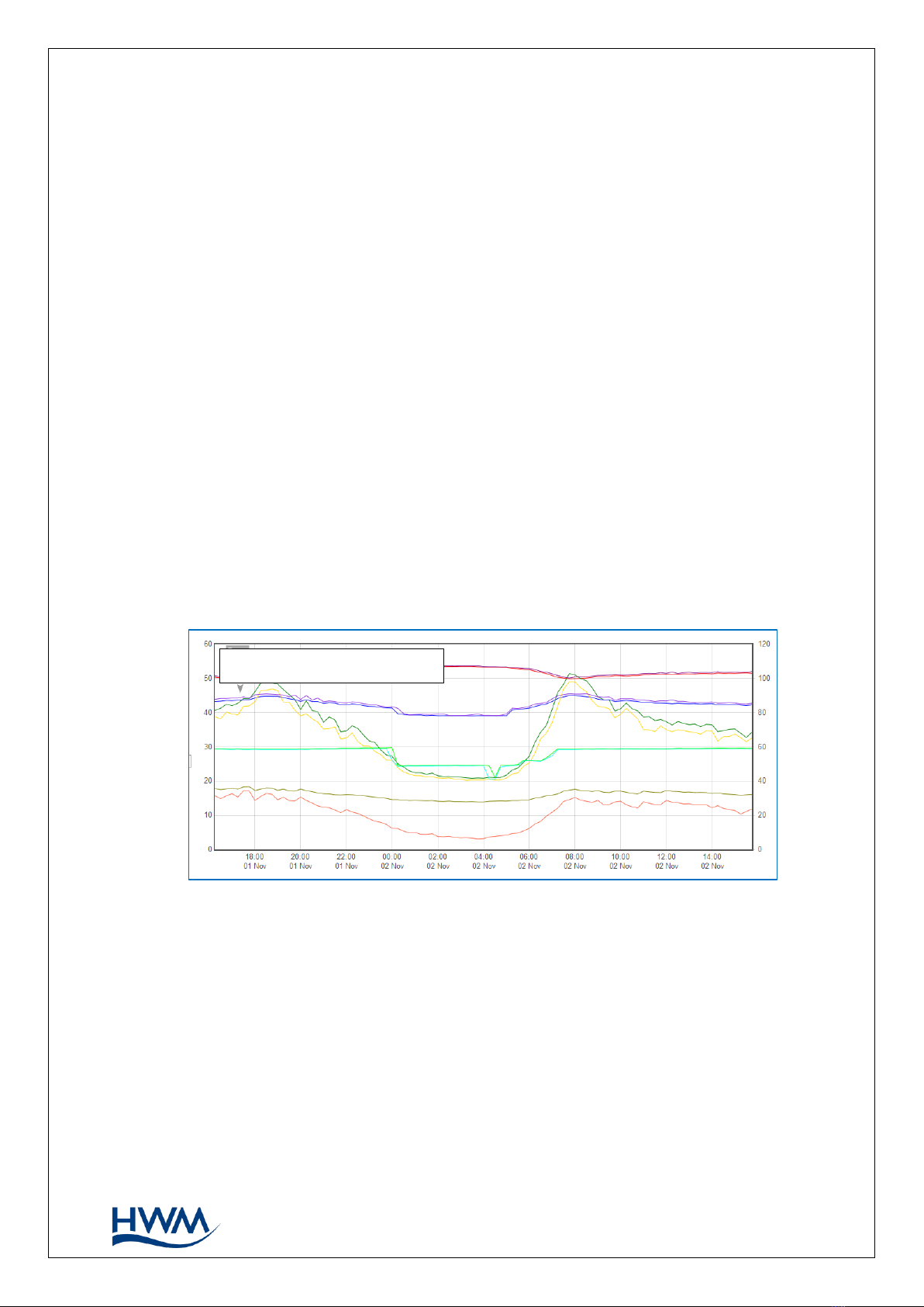
Viewing Secondary Recordings:
For sites which have logger models with Fast logging included, secondary recordings
may have been made. These are also stored on the server.
Your data viewer will have a means of displaying secondary recordings. It may, for
example, show a marker on the main trace to indicate the point where fast data is
available (e.g., where a transient occurred). Click the marker to provide a close-up view
of the transient.
2.8. INSTALLATION ACCESSORIES
Accessories (antenna and brackets for mounting the unit) are available to suit various
installation situations; discuss availability with your HWM representative.
(For illustration purposes only)
9
MAN-146-0006-A
3. ACTIVATING THE LOGGER AND COMMUNICATIONS LINK
3.1. LOGGER ACTIVATION PROCESS (FOR FIRST-TIME USE)
When shipped from the factory, the unit is in ‘shipping mode’ (deactivated; not logging
or calling in). This mode is suitable for shipping or long-term storage. To use the logger,
it must first be activated.
The process for doing this depends upon the logger setting for logging re-activation.
Various setting options are available (specified time, upon connection of an external
battery, upon the activation of a magnetic switch), but most loggers are set to start
‘immediately’ upon having their settings read by IDT and then saved back to the unit.
(Refer to the IDT user-guide for how to do this). The logger will then enter a status of
‘recording’, where it is executing its repetitive logging functions.
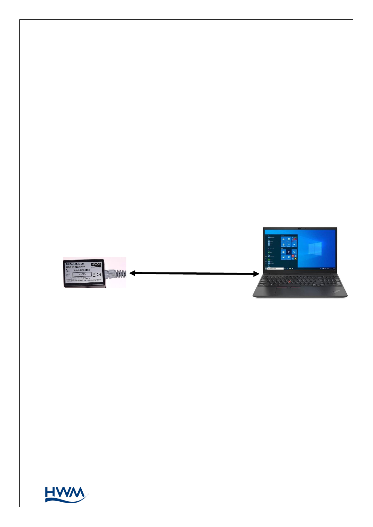
3.2. IDT -USED WITH A PC.
When programming the logger using a PC, the IR Reader should be plugged directly into
a USB-A port (or to USB-B or USB-C port via a suitable adaptor).
The PC provides power to the IR Reader.
Prior to use, the PC should have the IDT programming tool installed.
IR Reader
Personal Computer
(Comms
& power
via USB)
Figure 7. Communications path when using IR Reader directly.

10
MAN-146-0006-A
4. INTERFACES AND SENSOR TYPES (SUMMARY)
Note: Support for specific interfaces or functions vary and are dependent upon the
model supplied.
Sensors provide information for various physical parameters, and this information is
transferred to the logger via an appropriate electrical interface.
Each interface has associated logger settings for initiating the measurement and also to
correctly interpret the numeric data obtained. IDT is used to manage the settings.
Wired connections are made to the logger through one of the following means:
•A connector mounted through the logger case.
•A captive cable which passes through the logger case, usually via a gland fitting.
Connectors for sensors on Multilog-LX2 are usually 4-way, but can contain either pins or
sockets, as shown in Figure 10 and Figure 9. A dust-cap is available as an option to keep
unused connectors free of water and debris (see Figure 8).
Some connectors are single-purpose in nature (e.g., For connection of a single sensor).
However, other connectors may be multi-purpose in nature (e.g., For connection of both
a sensor and power from an additional battery).
Where a connector is multi-purpose, a Y-adaptor cable may be required to split out the
various functions.
For water pressure measurement, the electrical connection to the sensor may be made
via a 4-pin connector, as shown in Figure 10. This logger interface is known as an
“External Pressure” type. It allows a cabled pressure transducer (sensor) to be
connected to the logger. HWM can provide a variety of cabled pressure sensors with the
appropriate connector for the logger.
An alternative for water pressure measurement is for the
transducer (sensor) to be built into the unit, as shown in
Figure 11. This logger interface is known as an “Internal
Pressure” type. It allows pressurised water to be connected to
the logger directly, via the use of hoses fitted with a
quick-release connector.
Figure 10.
4-way connector with pins
Figure 9.
4-way connector with sockets
Figure 8.
Dust-cap option
Figure 11. Connection to internal
water pressure transducer

11
MAN-146-0006-A
For antenna, a different type of connector is used. Refer to section 5.16.
The Multilog-LX2 supports a variety of sensors and parameter measurements.
Examples are given below: (Dependant on model number ordered).
•Pressure.
Examples: - Direct connection to an internal transducer
(sometimes referred to as an ‘internal’ pressure sensor).
- Electrical connector for a wired transducer
(sometimes referred to as an ‘external’ pressure sensor).
•Distance to a water surface
Example: - Compatible with SonicSens2 sensor.
•Water depth.
Examples: - By using a SonicSens2 sensor
- By use of a submerged pressure gauge.
•Water leak detection (from pressurised water pipes).
Examples: - By use of a HWM Leak-Noise Sensor or Hydrophone.
•Water (or Gas) Consumption (Flow rate / total consumption).
Examples: - Various ‘Flow’ channels are available to suit a variety meter pulse
output formats.
•Temperature.
Example: - By use of a PT100 temperature sensor.
•Status Input
Example: - To detect an open/closed switch.
•GPS input (communication from Global Positioning System satellites)
Examples: - To determine current position.
To determine current time.
•0-1V or 01-10V input. (This is a generic sensor interface. The logger supports
inputs from externally powered sensors).
•4-20mA input. (This is a generic sensor interface. The logger supports
inputs from externally powered sensors).
•MODBUS (This is a widely used interface for sensor communications.
The logger supports inputs from externally powered sensors.
Optionally, the logger can provide power to some sensors).
•SDI-12 (This is a widely used interface for sensor communications.
The logger supports inputs from externally powered sensors).
•(Others).
Contact your sales rep for more information or to discuss your requirements.
For any given parameter, several sensors may be available with different types of
electrical interface. Sensors provided by HWM will include a cable with a suitable
connector for the supplied Multilog-LX2.

12
MAN-146-0006-A
5. INSTALLATION
5.1. SUMMARY OF INSTALLATION STEPS
•Check that an assessment of the work has been done and that any safety
measures are in place.
(E.g., Safety precautions, protective clothing and/or equipment being used).
•Check the logger is suitable for use at the installation site.
Check that you have the required sensors and antenna.
Consider where the equipment is going to be located within the available space
and that all cables and any hoses are of a suitable length.
•Check fittings are available to connect to any pressure measurement point.
•The logger, cables, and sensors should be kept away from sources of electrical
interference such as motors or pumps.
•Cables and hoses should be routed and secured so as to not cause any hazards.
Do not allow any equipment to rest on cables, connectors, or hoses as crush
damage can result.
•Attach the IR Reader interface to the logger and use IDT to read the logger
settings. (Refer to the IDT user-guide for guidance whenever needed).
•Update the logger firmware (if required).
(Consider downloading any existing data from the logger prior to upgrade).
•Use IDT to check or modify existing logger settings.
oProgram a local time-zone into the logger.
oSet timing intervals for making measurements (sample interval and log
interval). They should be configured to suit your application’s specific
logging requirements (minimise sampling rates to preserve battery life).
oSet Channels to produce measurement samples from each interface.
▪Configure the logger channel to match the sensor or other equipment
that the logger connects to.
(Check units of measure are correct, etc)
▪Ensure the sensor is mapped to the correct output channel number;
This is an identifier used when uploading the logged measurement
data to the server. (i.e., Channel numbers must match between logger
and DataGate).
▪Apply any required statistical functions to the background
measurement samples in order to produce logged data-points (saved
values).
oWhere required, undertake the setup of any additional options related to
the channel. (E.g., add an initial meter reading, pulse replication setting,
sensor calibration). Refer to the IDT user-guide for guidance regarding and
any additional settings related to an interface.
•For pressure sensors, electrically attach them but expose the sensor to the local
atmospheric pressure and re-zero them before commencing making a
connection to the measurement point.
•Install (position and connect) the sensors at their measurement point.
•Bleed any connections to water.

13
MAN-146-0006-A
•Where required, insulate any water-filled tubing connected to pressure
transducers to protect them from frost. (Insulating pipe covers can be supplied
upon request at additional cost or sourced locally from a hardware store).
•Ensure any electrical connections made on site are dry, durable, and water-tight.
•Use IDT to:
oTest the logger and sensors are functioning correctly.
(Some can be done pre-installation; others post installation).
oSetup the logger for any alarms. Consider the conditions for activating
alarm messages and also the conditions for the alarm to clear.
oCheck / modify the communications settings of the device, as required:
▪SIM settings (parameters for giving access to the cellular network).
▪Modem settings (Cellular Network technology).
▪Data delivery settings (server contact details).
▪Call-in times and protocol settings.
oVerify any changes to settings have been saved prior to leaving site.
Check that the logger is in a “recording” state.
•Where the logger has a GPS antenna connection, install (position and connect)
the GPS antenna for picking up the satellite communications.
Use IDT to test the GPS installation is correctly working.
•Install (position and connect) the antenna for server communications.
Use IDT to test the cellular communications performance.
•Ensure details of the site of logger deployment are recorded.
(The administration for the server could be handled by office staff, or the
installer could use the HWM Deployment app).
5.2. LOGGER
The logger must be mounted in a suitable location where the sensors to be attached
can reach their intended installation points. Position loggers, sensors, and antenna
away from sources of electrical interference such as motors or pumps.
Refer to the orientation shown in the diagram in section 2.1.1; The logger should be
installed as shown for optimum battery performance.
5.2.1. WALL-MOUNTING
Use wall-hanging brackets for mounting the logger.
Use the mounting holes that are provided on the logger.
Either secure with nuts and bolts or use plastic ties.
For best battery life, ensure the unit is reasonably level, as
shown in Figure 12.
Figure 12. Wall-mount example

14
MAN-146-0006-A
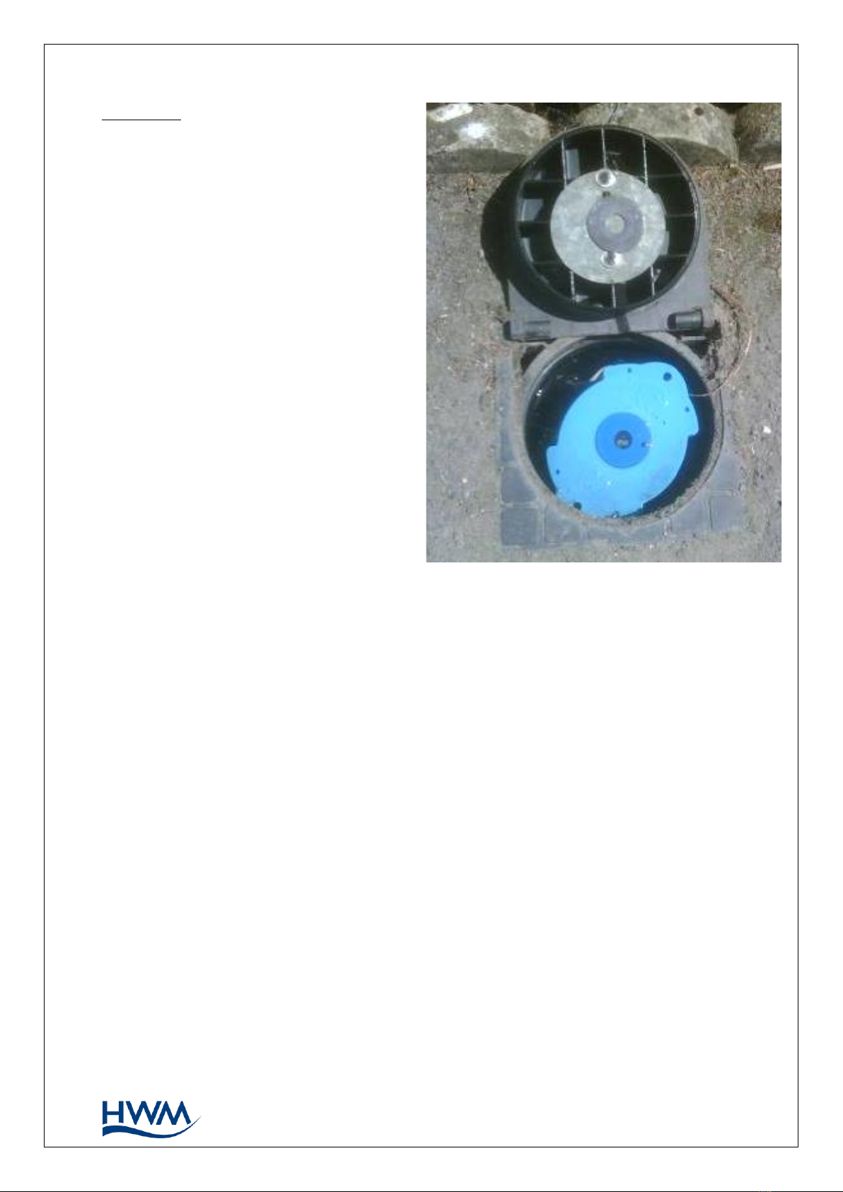
5.2.2. LOCATING IN PLASTIC-LIDDED CHAMBERS
Plastic lids usually have a metal plate fitted to the lid, sometimes on the back or internal
to the construction of the lid.
Internal aerial loggers may be more suitable for plastic lidded chambers, but in most
situations a logger with an external aerial should be considered.
The frost plug should always be fitted so as not to interrupt radio reception.
Drilling into the side of a plastic chamber is not recommended and could be dangerous
due to the high chance of damage to other services in close proximity.
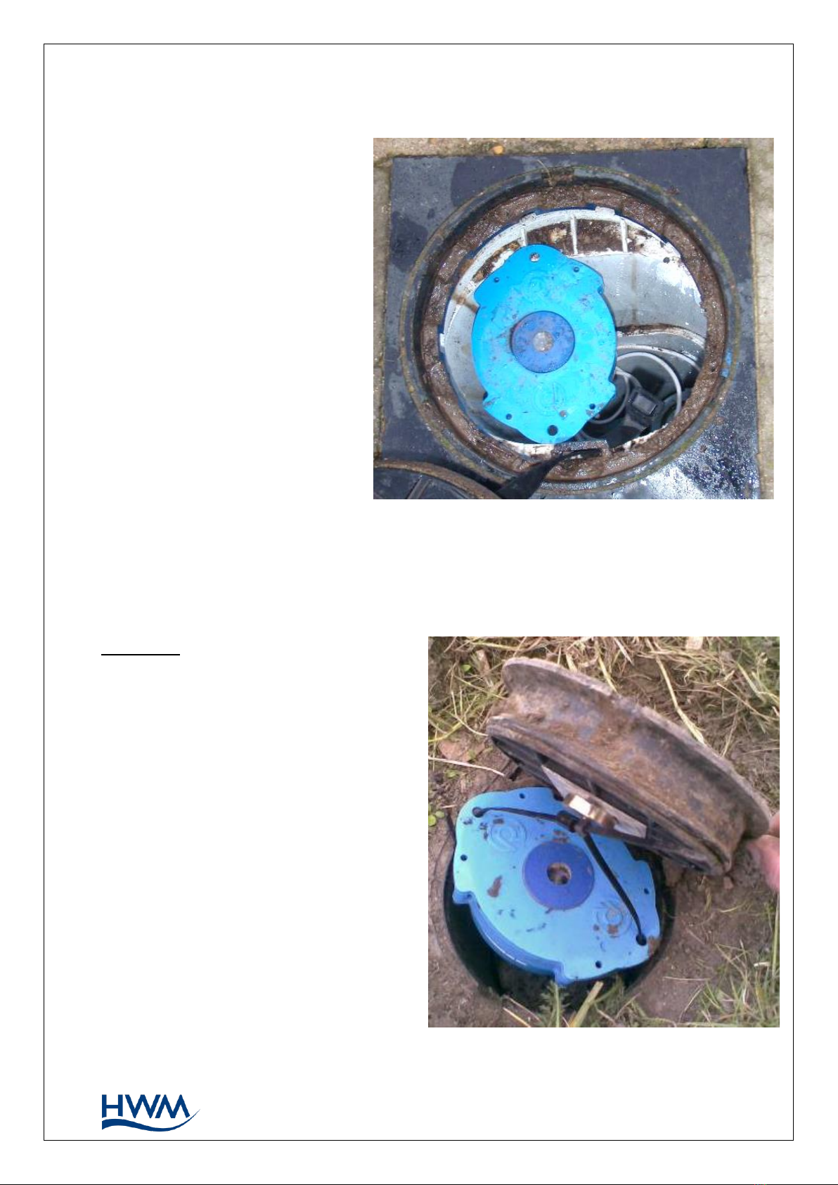
Multilog LX 2 Installation in Atplas box:
The design of the Multilog LX 2 means it is the correct size to rest on the ledges at the
top of an Atplas chamber.
If the logger has an internal antenna, then it should be mounted in an offset position to
avoid being directly underneath the metal plate moulded into the Atplas chamber lid.
Figure 13. Logger in Atplas box example
15
MAN-146-0006-A
Multilog LX 2 Installation in Talbot round lid box:
The Talbot equivalent of the Atplas
has a larger distance between the
white ledges at the top of the
chamber.
If there is vibration, then the logger
can slip off and fall to the bottom
of the box.
To overcome this the logger should
be fitted at an angle so the logger
is in a “pre-slipped” position.
If the logger has an internal
antenna,
then it should be mounted in an
offset position to avoid being
directly underneath the metal plate
moulded into the Talbot chamber
lid.
Multilog LX 2 Installation in Talbot –Flip Lid box:
When correctly installed the Talbot flip lid box offers a smooth vertical tube with no
available fixing point for the LX logger. Alternative solutions are required.
Example 1:
A magnet with “P” clip can be attached
to the lid and the logger suspended from
the magnet using a cable tie.
Figure 14. Logger in Talbot round lid box example
Figure 15. Logger in Talbot flip-lid box P-clip example
16
MAN-146-0006-A
Example 2:
A 6mm plastic tube can be pushed down
the outside of the chamber and the
logger hung on the protruding end.
5.3. PRESSURE SENSOR INPUTS
5.3.1. RE-ZERO FACILITY (FOR PRESSURE RELATIVE TO LOCAL ATMOSPHERE)
Pressure sensors supplied by HWM normally measure pressure relative to atmospheric
pressure. Since there can be some variation in local atmosperic pressure (e.g., due to
altitude), the loggers have a facility to re-zero the pressure sensor.
This must be done with the sensor exposed to atmospheric air.
Prior to connecting the transducer to the actual measuring point, leave it exposed to
air. Then “re-zero” the sensor using the method found in the IDT user-guide.
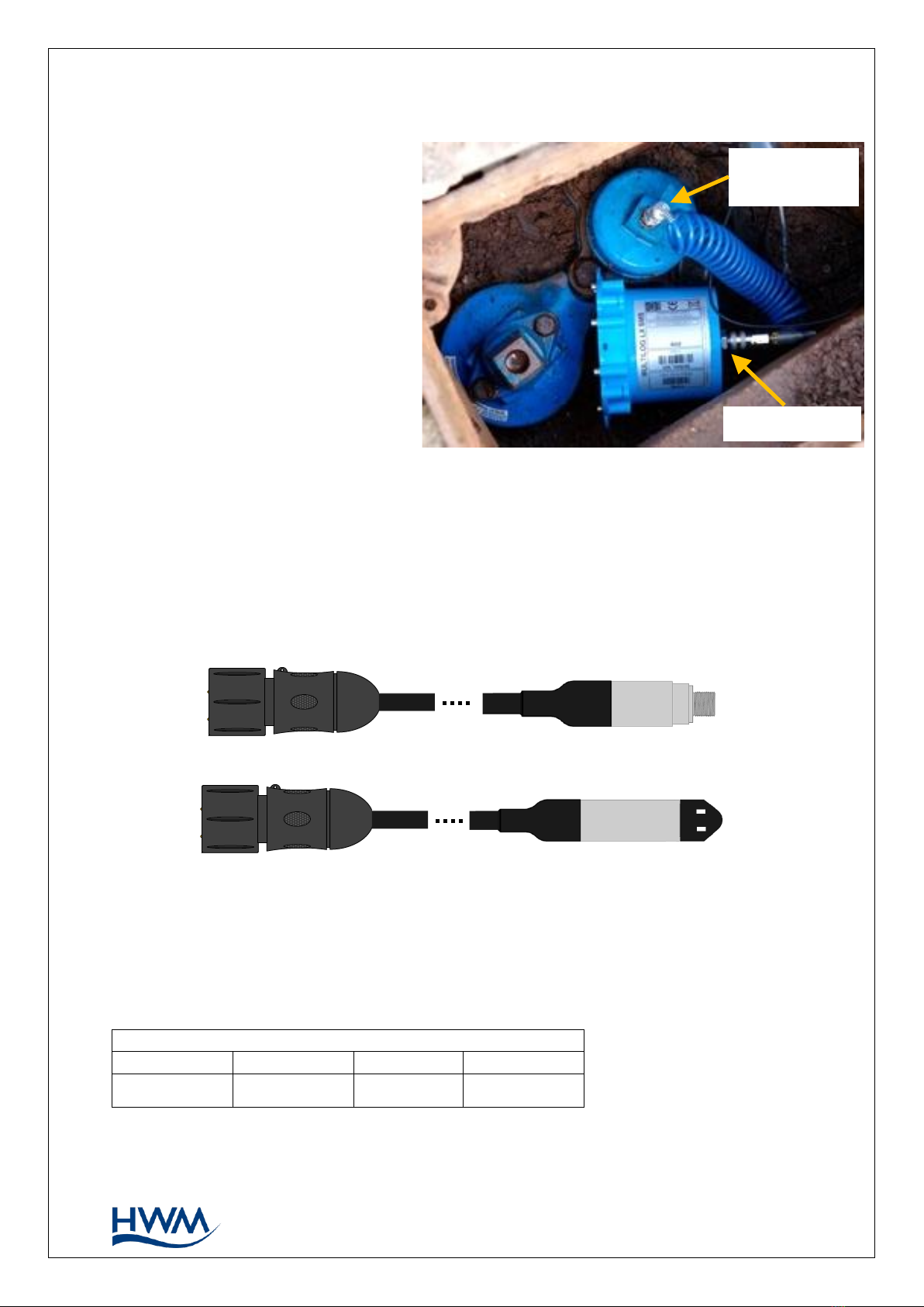
5.3.2. PRESSURE SENSOR (INTERNAL)
A pressure input may be presented as a built-in transducer (as shown in Figure 11, on
page 10), which connects directly to the fluid via a hose using a quick-release connector.
Note: Do not connect the sensor to the measurement point before going through the
re-zero (to local atmospheric pressure) process, if required.
The input will be labelled with the pressure rating of the transducer.
E.g., ‘PRESSURE (10 BAR)’.
Connect the pressure tapping on the pipe (measurement point) to the pressure
transducer of the logger using a suitable interconnecting hose. (For an example, see
Figure 17.) Ensure the hose is bled, for correct operation.
Figure 16. Logger mount using a plastic tube example
17
MAN-146-0006-A
This interface is factory calibrated. No on-site calibration is required.
Note: Add insulation to the pipe
and logger to prevent
freezing.
If the water in the hose or
the logger itself freeze, there
is a danger of permanent
damage to the pressure
transducer.
5.3.3. PRESSURE SENSOR (EXTERNAL)
A pressure input may be presented as an electrical interface, using a 4-pin MIL-Spec
connector (as shown in Figure 10 on page 10).
Cabled pressure sensors for the Multilog LX2 are available from HWM. For most
situations, sealed type pressure (or depth) sensors are used, and the sensor will be
wired directly to the connector, as shown in Figure 18.
The logger temporarily applies power to the sensor just before (and during) making a
measurement.
The logger interface will be labelled “EXTERNAL PRESSURE” (or similar).
The pinout of the connector is shown below.
Logger bulkhead connector pinout : External Pressure
A
B
C
D
V (+) ; (PWR)
V (+) ; (Signal)
V (-) ; (PWR)
V (-) ; (Signal)
Pressure point
on pipe
Pressure input
Figure 17. Example connection to a built-in pressure transducer
Figure 18. Cabled pressure and depth sensors.
Table of contents
Other FCS Industrial Equipment manuals


