FDS FD141CV-C-6 User manual

Document Number:
MAN –FD141CV-C-6
Rev:
B
Revision Date:
04/27/2017
Page 1 of 34
©2017 FDS Avionics Corp.
All Rights Reserved.
TECHNICAL SUPPORT
470-239-7421 or FDSAvionics.com
Installation and Operation Manual
FD141CV-C-6
14” Day/NVG Monitor

Document Number:
MAN –FD141CV-C-6
Rev:
B
Revision Date:
04/27/2017
Page 2 of 34
©2017 FDS Avionics Corp.
All Rights Reserved.
TECHNICAL SUPPORT
470-239-7421 or FDSAvionics.com
Table of Contents
General Information.................................................................................................................3
Front View..................................................................................................................................3
Additional Information ...........................................................................................................3
Specifications.............................................................................................................................4
Installation Instructions ..........................................................................................................4
Power...........................................................................................................................................5
Wiring Suggestions ..................................................................................................................5
Composite Wiring.....................................................................................................................5
Power and Ground Wiring......................................................................................................6
Power/Video Pin Out ...............................................................................................................7
HDSDI Pin Out .........................................................................................................................8
Operation Instructions.............................................................................................................9
Button Control ...........................................................................................................................9
Accessing the Menu Systems................................................................................................10
User Menu’s ...................................................................................................................... 10- 23
Technical Drawing Monitor Only .......................................................................................24
Technical Drawing –Co-Pilot Position ..............................................................................25
Technical Drawing –Pilot Position.....................................................................................26
Portrait Co-Pilot.......................................................................................................................27
Portrait Pilot ............................................................................................................................28
User Instructions for Attaching Arm Support......................................................... 29 & 30
Maintenance and Inspections...............................................................................................31
Technical Support...................................................................................................................32
Instructions for Continued Airworthiness ........................................................................32
Warranty ...................................................................................................................................33
Log of Revisions......................................................................................................................34

Document Number:
MAN –FD141CV-C-6
Rev:
B
Revision Date:
04/27/2017
Page 3 of 34
©2017 FDS Avionics Corp.
All Rights Reserved.
TECHNICAL SUPPORT
470-239-7421 or FDSAvionics.com
General Information
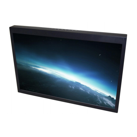
The FD141CV-C-6 is a special mission 14” night vision/sunlight readable widescreen
monitor.
Built with retrofit aircraft integration in mind, the display can switch between three video
sources using the front button controls. The display includes a daylight/NVG rocker
switch mounted on the front bezel. Additional functions can be added using the 8 bezel
keys; 4-buttons on each side located on the front face of the bezel. These functions are
generated by the mission computer via USB connection through the circular 22-pin
connector.
Front View
Additional Information
The FD141CV-C-6 utilizes a state of the art digital video decoding chipset for video input.
The available video sources are HDSDI (High Definition SDI), VGA (Computer Video,
such as a Moving Map) and Composite Video (Camera, Standard Definition DVD).
The LCD is protected with a .060” non-glare Lexan lens to prevent scratching of the LCD,
and to meet stringent FAA abrasive load criteria.

Document Number:
MAN –FD141CV-C-6
Rev:
B
Revision Date:
04/27/2017
Page 4 of 34
©2017 FDS Avionics Corp.
All Rights Reserved.
TECHNICAL SUPPORT
470-239-7421 or FDSAvionics.com
Specifications
Display Type
14.1” TFT Color LCD
Display Color
262K Colors
Screen Resolution
XGA 1024 x 768
Display Size
14.7”(W) x 9.7”(H) x 1.7” (D)
Weight
6 lbs. 9 oz.
Power
28V DC @ 2.0 Amps
Operating Temperature
0-50° C (32-122° F)
Video Input (via TVS06RF-13-35P)
HDSDI, VGA, Composite Video
Video Type Supported
NTSC/PAL
Screen Control
On Screen Display Menu
Materials
Aluminum
Certifications
Mil-STD 704 –Table IV for 28VDC
Altitude –MIL-STD-810F, Method 500.4, Procedure
II (Operation)
Low Temperature –MIL-STD-810F, Method 502.4,
Procedure II (Operation)
Humidity –MIL-STD-810F, Method 507.4, Procedure
II (Aggravated)
Vibration Performance –MIL-STD-810E, Method
514.4, Procedure I, Category 4
Shock –MIL-STD-810E, Method 516.4, Figure
516.4-4, Procedure I (Functional Shock)
Shock –MIL-STD-810E, Method 516.4, Figure
516.4-4, Procedure V (Crash Safety)
The
Explosive Atmosphere - RTCA-DO-160G, Sec 9.6.2
Cat E
Solar Radiation –MIL-STD-810F (N3) Method 505.4,
Procedure I, Cycle A1
High Temperature Operation –MIL-STD-810F (N3)
Method 501.4, Procedure II
Rapid Decompression –MIL-STD-810F (N3) Method
500.4, Procedure III,
Conducted Susceptibility MIL-STD-461F (N3)
Method 505.4, Procedure I, Cycle A1
Solar Radiation –MIL-STD-810F (N3) Method 505.4,
Procedure I, Cycle A1
Installation Instructions
All cabin equipment, such as the FD141CV-C-6, should be installed on a non-essential
bus and have a dedicated circuit breaker.

Document Number:
MAN –FD141CV-C-6
Rev:
B
Revision Date:
04/27/2017
Page 5 of 34
©2017 FDS Avionics Corp.
All Rights Reserved.
TECHNICAL SUPPORT
470-239-7421 or FDSAvionics.com
Power
This is a 28VDC monitor that requires 2.0 Amps of power to operate. The unit turns on
automatically upon power application. See Power and Ground Wiring below for more
details.
Wiring Suggestions
Avoid routing video wiring parallel to:
AC wiring
Strobe wiring
DC motor supply cables
Inverter cabling
Or any other potential noise source
Composite Wiring
Recommended cable for composite and audio purposes is PIC 75 Ohm Coax, P/N
V76261. This is a lightweight, flexible, and low signal loss cable which meets FAA
flammability requirements of FAR 23.1359(d), FAR 25.853(a) and FAR 25.869(a)(4).
Similar aviation coaxial cable can be used from other vendors, as well. Some aircraft are
prone to AC noise - we recommend adding to the composite source a 75Ohm video
isolation transformer such as Deerfield Laboratory, Inc. Part No. 162-1
(www.deerfieldlab.com, (650) 632-4090). In most cases this should be added to the video
output of the source.

Document Number:
MAN –FD141CV-C-6
Rev:
B
Revision Date:
04/27/2017
Page 6 of 34
©2017 FDS Avionics Corp.
All Rights Reserved.
TECHNICAL SUPPORT
470-239-7421 or FDSAvionics.com
Power and Ground Wiring
The rated current of the equipment and associated voltage drop should be taken into
consideration when selecting wire gauge. The following example is based on an install with a
28VDC power system, 1.5 amp equipment load and a total of 50 feet of wire between the
circuit breaker, monitor and ground.
Example: 22awg wire has 16.2 Ohms per 1000 feet, this equates to .81 Ohms for 50 feet.
1.5 Amp of current on .81 Ohms will drop 1.22 Volts.
Resistance of Wire Type M22759/16-**
(** = Gauge)
Gauge (AWG)
OHMS/1000’
24
26.20
22
16.20
20
9.88
16
4.81
12
2.02
10
1.26
8
.701
Also, use short heavy gauge wire and a clean tight connection for ground.
It is the installer's responsibility to understand the product's requirements in order to install the
product in compliance with industry standards and safety.

Document Number:
MAN –FD141CV-C-6
Rev:
B
Revision Date:
04/27/2017
Page 7 of 34
©2017 FDS Avionics Corp.
All Rights Reserved.
TECHNICAL SUPPORT
470-239-7421 or FDSAvionics.com
Power/Video
Pin out for 22 PIN Circular Connector
CONNECTOR P/N: TVPS00RF-13-35S
CONTACT P/N: M39029/58-360
STRAIN RELIEF P/N: M85049/38S13N
MATING FACE
Pin
Number
Description
1
28 VDC Power
2
28 VDC Ground
3
USB Data + (Green)
4
USB Data –(White)
5
USB Shield
6
Composite Video –Shield
7
Composite Video –Signal
8
N/C
9
N/C
10
Horizontal Sync (Pin 13 on Standard VGA)
11
Sync Ground (Pin 10 on Standard VGA)
12
Red Video (Pin 1 on Standard VGA)
13
Green Video (Pin 2 on Standard VGA)
14
Blue Video (Pin 3 on Standard VGA)
15
Blue Ground (Pin 8 on Standard VGA)
16
USB + 5VDC (Red)
17
USB Ground (Black)
18
N/C
19
Vertical Sync (Pin 14 on Standard VGA)
20
Red Ground (Pin 6 on Standard VGA)
21
Green Ground (Pin 7 on Standard VGA)
22
N/C

Document Number:
MAN –FD141CV-C-6
Rev:
B
Revision Date:
04/27/2017
Page 8 of 34
©2017 FDS Avionics Corp.
All Rights Reserved.
TECHNICAL SUPPORT
470-239-7421 or FDSAvionics.com
HDSDI (INPUT)
CONNECTOR P/N: Amphenol 112235
Pin
Description
Center
Video Signal
Shell
Video Return

Document Number:
MAN –FD141CV-C-6
Rev:
B
Revision Date:
04/27/2017
Page 9 of 34
©2017 FDS Avionics Corp.
All Rights Reserved.
TECHNICAL SUPPORT
470-239-7421 or FDSAvionics.com
Operation Instructions
The FD141CV-C-6 is continuously on but may be de-energized by removing power from
the display system. No pilot or aircrew action is necessary during flight or ground
operation.
When applying 28VDC power, the display will turn on and look for a valid input. If no
input is found, the display will go to standby mode. The operator will be able to change
the video output from the FD141CV-C-6 using the video source select switch on the LCD
monitor.
Button Controls
Located on the bottom front of the FD141CV-C-6 are 8 buttons, and a backlit NVG
Rocker Switch. Functionality for these buttons are as follows:
BUTTON
DESCRIPTION
M
Activates the OSD menu or goes to previous menu.
Moves the highlight icon down to the function that user
wants.
Moves the highlight icon up to the function that the user
wants.
Moves the highlight icon left to the function that the user
wants.
Moves the highlight icon right to the function that the user
wants.
A
Auto-adjusts the display’s size and position.
S
Cycles through source inputs.
P
Powers monitor on and off.
Rocker
Switch
This rocker switch, switches between daylight and night
vision.
M

Document Number:
MAN –FD141CV-C-6
Rev:
B
Revision Date:
04/27/2017
Page 10 of 34
©2017 FDS Avionics Corp.
All Rights Reserved.
TECHNICAL SUPPORT
470-239-7421 or FDSAvionics.com
Accessing the Menu System
With the OSD (On Screen Display) off, push the MENU
button to activate the main OSD menu.
Press the UP or DOWN buttons to move from one function to another. As you
move from one icon to another, the function name changes to reflect the
function or group of functions represented by that icon.
Press the MENU button once to return to the main menu to select another
function or press twice to exit from the OSD.
To save the setting values, exit the OSD menu.
Image Menu
Brightness
Adjust to brighten or darken the picture.
Contrast
Adjust to increase or decrease picture contrast.
Saturation
Adjust to increase or decrease - a greater saturation will
have vivid color; a level of zero will reduced the picture to
shades of grey.
Hue
Adjust to increase or decrease the level of color in the
picture.
Sharpness
Adjust to sharpen or soften the picture.

Document Number:
MAN –FD141CV-C-6
Rev:
B
Revision Date:
04/27/2017
Page 11 of 34
©2017 FDS Avionics Corp.
All Rights Reserved.
TECHNICAL SUPPORT
470-239-7421 or FDSAvionics.com
Display Menu
Scan Mode
Method of adjusting widescreen film images so that they can
be shown within the proportions of a standard definition 4:3
ratio.
Over Scan
Full image area to the electronic edge of the signal.
Aspect Mode
The ratio between the width and height of an image.
Full Screen
Allows full screen image on the monitor regardless of Scan
or Over Scan mode.

Document Number:
MAN –FD141CV-C-6
Rev:
B
Revision Date:
04/27/2017
Page 12 of 34
©2017 FDS Avionics Corp.
All Rights Reserved.
TECHNICAL SUPPORT
470-239-7421 or FDSAvionics.com
Display Menu (Continue)
Auto Adjust
Automatically optimize your monitors image position, clock, and
phase.
Image Position
Press the and buttons to change the image of the screen display
area.
Phase
Press the and buttons to remove any horizontal distortion and
clear or sharpen the displayed characters.
Clock
Press the and buttons to minimize any vertical bars or stripes
visible on the screen background. The horizontal screen size will also
change.
Zoom In and Out
Press the and buttons to zoom in and out within the screen
display area. After you zoom in, the Horizontal and Vertical controls
are active. Use the and buttons to move horizontally and
vertically within the zoomed area.

Document Number:
MAN –FD141CV-C-6
Rev:
B
Revision Date:
04/27/2017
Page 13 of 34
©2017 FDS Avionics Corp.
All Rights Reserved.
TECHNICAL SUPPORT
470-239-7421 or FDSAvionics.com
Image Position
Click on the arrow buttons to change the image of the screen
displayed in the main area. These image indicators represent each
computer connected to make up the Quad.

Document Number:
MAN –FD141CV-C-6
Rev:
B
Revision Date:
04/27/2017
Page 14 of 34
©2017 FDS Avionics Corp.
All Rights Reserved.
TECHNICAL SUPPORT
470-239-7421 or FDSAvionics.com
Color Temp Menu
Mono
This mode uses only the luminance value.
6500K
Select to give the white color’s a reddish tint.
7500K
Select to give the white color’s a neutral tint.
9300K
Select to give the white color’s a bluish tint.
User
User manually adjusts color.

Document Number:
MAN –FD141CV-C-6
Rev:
B
Revision Date:
04/27/2017
Page 15 of 34
©2017 FDS Avionics Corp.
All Rights Reserved.
TECHNICAL SUPPORT
470-239-7421 or FDSAvionics.com
Press the and buttons to change the color saturation

Document Number:
MAN –FD141CV-C-6
Rev:
B
Revision Date:
04/27/2017
Page 16 of 34
©2017 FDS Avionics Corp.
All Rights Reserved.
TECHNICAL SUPPORT
470-239-7421 or FDSAvionics.com
PIP (Picture in Picture) Menu

Document Number:
MAN –FD141CV-C-6
Rev:
B
Revision Date:
04/27/2017
Page 17 of 34
©2017 FDS Avionics Corp.
All Rights Reserved.
TECHNICAL SUPPORT
470-239-7421 or FDSAvionics.com
PIP Position -
The PIP Screen
allows the user
to change the
size of the
screen they want
to see. PIP Mode
will change the
PIP to Small,
Medium, Large,
and Side by
Side.
PIP Source/ PIP
Position - The
screens will
change
depending on
the Quad
connections
chosen for PIP
(ie, Analog,
HDMI). The PIP
position may also
move to any
corner and/or
side by side
within the
screen.

Document Number:
MAN –FD141CV-C-6
Rev:
B
Revision Date:
04/27/2017
Page 18 of 34
©2017 FDS Avionics Corp.
All Rights Reserved.
TECHNICAL SUPPORT
470-239-7421 or FDSAvionics.com
PIP Swap –This
function will
replace one
image with
another image
connected in the
quad.
Side by Side
allows the user
to view two
screens at one
time in an equal
amount of space.

Document Number:
MAN –FD141CV-C-6
Rev:
B
Revision Date:
04/27/2017
Page 19 of 34
©2017 FDS Avionics Corp.
All Rights Reserved.
TECHNICAL SUPPORT
470-239-7421 or FDSAvionics.com
Quad Screen Menu
Multi
Vision
Use the Multi Vision screen to manage your Quad Views. Multi Vision can
be turned on or off here by changing the option from off to on.

Document Number:
MAN –FD141CV-C-6
Rev:
B
Revision Date:
04/27/2017
Page 20 of 34
©2017 FDS Avionics Corp.
All Rights Reserved.
TECHNICAL SUPPORT
470-239-7421 or FDSAvionics.com
Image
Control is
maintained
on this
screen for
each
individual
picture.
Select
Column or
individual
quad area
to manage
the size of
the
images.
Table of contents
Other FDS Monitor manuals
FDS
FDS FD151CV-QUAD User manual

FDS
FDS FD101DD-BH User manual
FDS
FDS FD102CV-LP-S User manual
FDS
FDS FD70CV-M-C-6 User manual
FDS
FDS FDPMAID Series User manual
FDS
FDS FD50HMT User manual
FDS
FDS FD220CV-C-1 User manual
FDS
FDS FD70ARM-G User manual
FDS
FDS FD171CV-C-1 User manual
FDS
FDS FD215CV-C-Q-VGA User manual
FDS
FDS FD171CV-C-4 User manual

FDS
FDS FD102CMT User manual
FDS
FDS FD102CV-C-7-L User manual

FDS
FDS FD215CV-C-5 User manual
FDS
FDS FD102CV-C-1 User manual
FDS
FDS FD70ARM User manual
FDS
FDS FD141CV-C-3 User manual
FDS
FDS FD215CV-C-7 User manual
FDS
FDS FD171CV VER HDSDI User manual
FDS
FDS FD171CV VER HDSDI User manual
