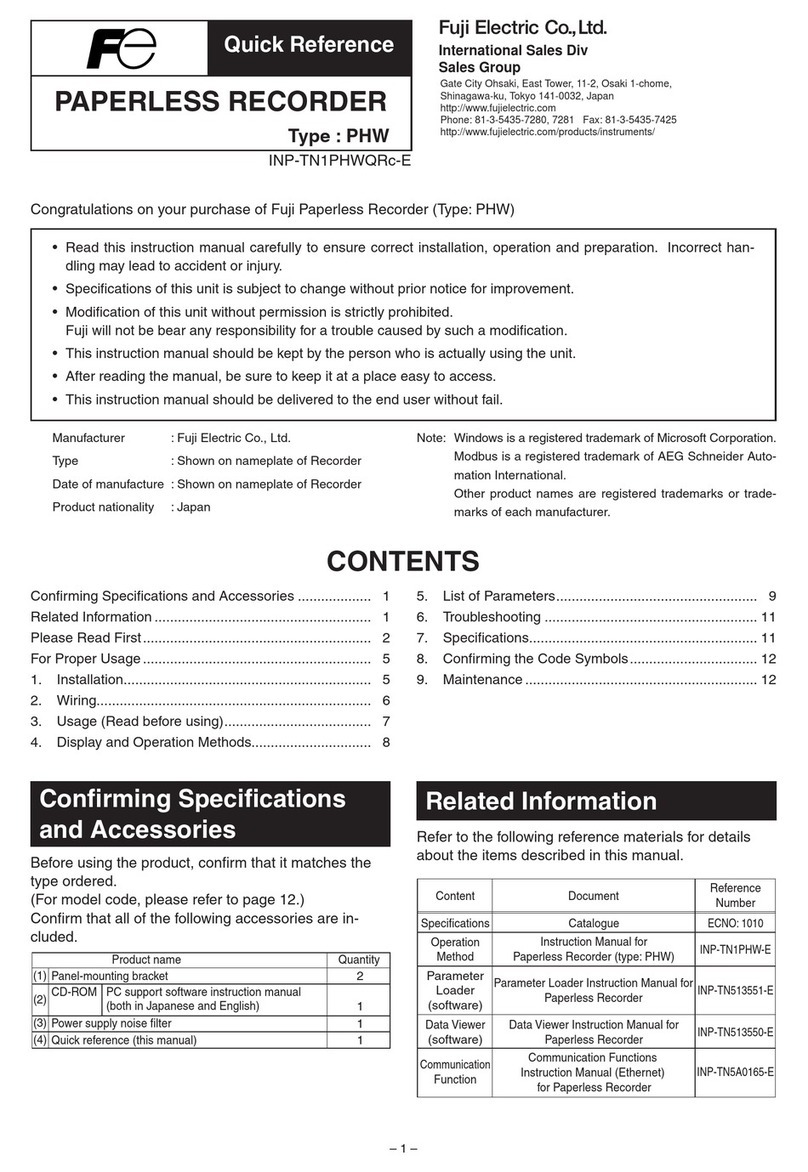
FE MSR128LUS User manual

MSR128LUS/MSR128LUV USERS MANUAL EM-7375 Rev.2
PC RECORDER
FOR 53U MULTI POWER MONITOR
Software model: MSR128LUS, MSR128LUV
Users Manual
Fuji Electric France S.A.S.
46, Rue Georges Besse - Z I du Brézet - 63 039 Clermont-Ferrand cedex 2 FRANCE
France : Tél. 04 73 98 26 98 - Fax 04 73 98 26 99 - International : Tél. (33) 4 7398 2698 - Fax. (33) 4 7398 2699
E-mail : sales.dpt@fujielectric.fr – WEB : www.fujielectric.fr

2
MSR128LUS/MSR128LUV USERS MANUAL EM-7375 Rev.2
Contents
1. GENERAL DESCRIPTIONS ........................................................................ 5
1.1 PRECAUTIONS TO USE THE MSR128LU ON YOUR PC ......................................................... 5
1.2 FEATURES OF THE MSR128LU ................................................................................................ 6
1.3 PC REQUIREMENTS.................................................................................................................. 7
2HARDWARE SETUP.................................................................................... 8
2.1 CONFIGURING THE 53U ........................................................................................................... 8
2.2 CONNECTING TO THE PC.........................................................................................................9
2.2.1 MODBUS RTU .................................................................................................................9
2.2.2 ETHERNET MODBUS TCP/IP....................................................................................... 10
3INSTALLING THE MSR128LU .................................................................. 11
3.1 INSTALLING THE MSR128LU FROM THE DOWNLOADED ARCHIVE....................................11
3.2 UNINSTALLING THE MSR128LU ..............................................................................................11
3.3 STARTING THE MSR128LU ......................................................................................................11
4SETTING UP THE MSR128LU .................................................................. 12
4.1 BASIC SETTING ....................................................................................................................... 12
4.1.1 OPERATING MODE....................................................................................................... 12
4.1.2 GRAPH DIRECTION...................................................................................................... 13
4.1.3 GRAPH MODE............................................................................................................... 13
4.1.4 STORAGE PERIOD ....................................................................................................... 13
4.1.5 COMMUNICATION PORT.............................................................................................. 14
4.2 NODE SETTING........................................................................................................................ 15
4.3 PEN SETTING........................................................................................................................... 16
4.3.1 COMMON INFORMATION............................................................................................. 16
4.3.2 DETAIL INFORMATION (ANALOG) ............................................................................... 17
4.3.3 DETAIL INFORMATION (DISCRETE)............................................................................ 19
4.3.4 OTHER CONTROLS...................................................................................................... 19
4.4 STORE SETTING ...................................................................................................................... 20
4.4.1 STORING CYCLE .......................................................................................................... 20
4.4.2 NORMAL MODE ............................................................................................................ 20
4.4.3 REMOTE TRIGGER....................................................................................................... 21
4.4.4 EVENT RECORDING .................................................................................................... 21
4.4.5 AUTO MODE..................................................................................................................22
4.4.6. FILE VOLUME................................................................................................................ 22
5. RECORD .................................................................................................... 23
5.1 MENU BAR................................................................................................................................ 23
5.2 ELEMENTS ON THE RECORD VIEW ...................................................................................... 24
6. RETRIEVE.................................................................................................. 26
6.1 MENU BAR................................................................................................................................ 26
6.2 ELEMENTS ON THE RETRIEVE VIEW.................................................................................... 26

3
MSR128LUS/MSR128LUV USERS MANUAL EM-7375 Rev.2
7. ALARM HISTORY ...................................................................................... 29
8. FILE ............................................................................................................ 30
8.1 DATA FILE & FOLDER .............................................................................................................. 30
8.2 PARAMETER FILE .................................................................................................................... 30
8.3 MSR128LU FILE TYPES ........................................................................................................... 31
8.4 CSV DATA FORMAT.................................................................................................................. 31
Appendix A: Software version information.................................................. 33

4
MSR128LUS/MSR128LUV USERS MANUAL EM-7375 Rev.2
INTRODUCTION
Thank you for choosing M-System’s PC Recorder. This instruction manual describes functions of PC Recorder for
the 53U Multi Power Monitor, its PC requirements, input module, and how to operate the MSR128LUS and
MSR128LUV (hereunder referred to as ‘MSR128LU’) software programs.
The MSR128LU is aWindows-PC-based software program dedicated to be used with the 53U Multi Power Monitor,
to monitor and record its measured data. To program the 53U’s configurations, you need to access its program via
the front keys, or to use the dedicated PC configuration software, model 53UCFG. Other hardware modules cannot
be used with the MSR128LU.
The data used for the recorder is saved in CSV format allowing easy export to other Windows programs (e.g.
Microsoft Excel).
In order to ensure maximum performance of the PC Recorder, we recommend that you carefully examine the envi-
ronments of the PC and other connected devices. Please remember that the overall reliability of the MSR128LU as
a recording device depends upon that of the PC including its OS.

5
MSR128LUS/MSR128LUV USERS MANUAL EM-7375 Rev.2
1. GENERAL DESCRIPTIONS
1.1 PRECAUTIONS TO USE THE MSR128LU ON YOUR PC
1. The MSR128LU is designed as package application, usable on PC running Windows 2000 and Windows XP.
Consider the fact that the MSR128LU constantly reads input signal and plots entire chart screen at its fastest
storing cycle of 0.5 sec. when you choose the CPU and graphic capabilities of PC.
2. DO NOT use another application program while the MSR128LU is running.
3. Remember that the overall reliability of the MSR128LU as a recording device depends upon that of the PC
including its OS.
4. The MSR128LU is designed to use in a single window on a single PC, not for use in multiple windows or to be
shared on LAN.
5. Disable the power saving mode: Select on the PC’s desktop ‘Properties – Screen Saver – Power – Power
Schemes’and set‘Never’to all items. With laptops, disable any key operations to initiate an automatic shutdown
other than the power switch. Disable also the system stand-by mode or any other power saving features.
6. Disable animating screen savers in order to avoid extra load to the PC when running the MSR128LU.
7. It is recommended not to copy more than necessary shortcuts or exe. files on the desktop. We recommend to
delete exe. files related to web site contents in order to avoid any disturbance in plotting.
8. Storing cycles of 500 msec. or slower are usable. High speed mode (50 msec. storing cycle) is unavailable.
9. Use an independent LAN for the MSR128LU. Sharing the network with other systems may cause an instability
or interference on both systems.
10.If you intend to use the PC Recorder in the following environments or conditions, redundant and/or failsafe
system designs should be used to ensure the proper degree of reliability and safety.
–Environments or conditions which are not defined in this manual
–Nuclear power control devices, railway control devices, aircraft control devices, transportation vehicles, fuel
control equipment, medical equipment, recreational equipment, safety equipment, and other critical equip-
ment for which safety must be secured according to relevant laws.
–Those devices which inherently require extremely high level of safety and reliability.

6
MSR128LUS/MSR128LUV USERS MANUAL EM-7375 Rev.2
1.2 FEATURES OF THE MSR128LU
On the Record view, the MSR128LU reads and plots input signals on the screen, and saves data as record files.
Additionally, it compares the signals with the preset alarm conditions and accordingly outputs a contact signal to the
predetermined output point. Pen configurations including alarm setting can be modified on this view.
On the Retrieve view, the MSR128LU searches and shows historical recorded data files. The MSR128LU continues
sampling even while the main recording window is inactive.
The data files are saved in CSV format, which can be directly exported to general-purpose spreadsheet programs
such as Microsoft EXCEL. They can be stored also in removable storage media for later use, for example, using the
Retrieve view or Microsoft Excel program on another PC.
In addition to the functions of conventional recorders, those of data logging is incorporated all-in-one into the
MSR128LU, thanks to extensive, analytical, communicative and administrative capabilities of a PC.
It can be called as “chartless” recorder.
Figure 1.2 shows a map of various options available on the menu bar and control panel in the MSR128LU program.
Figure 1.2: MSR128LU options map.
Setting Operation mode
Graph direction
Graph mode
Communication port
Basic setting
Node setting
Storage period
Digital Hide
Digital
Alarm History
Reload
Search condition
Clear
Retrieve Divide
Date time
Current
Basic information
Detail
Store setting
Common information
Detail information
Pen setting

7
MSR128LUS/MSR128LUV USERS MANUAL EM-7375 Rev.2
1.3 PC REQUIREMENTS
PC: IBM PC/AT or compatible
RS-232C port may have predefined use for certain types of PC, which could require modifica-
tions in driver software or system configuration.
Operating system: Windows 2000 or Windows XP SP1, SP2
Screen area: MSR128LUS 800 by 600 pixels
MSR128LUV 640 by 480 pixels
Display colors: 65000 colors or more (16 bit high color)
CPU: Pentium III 800 MHz or higher (Use the secondary cache with Celeron CPU)
Memory: 128 MB recommended for Windows 2000, 256 MB for Windows XP
Input device: 53U
Protocol coverter: models 72EM-M4, 72EM2-M4
Hard disk area: Using an internal drive is recommended. Performance of the MSR128LU may be impaired
with using external one, connected via SCSI for example.
The hard disk must have a enough space, and removable storage media must be available for
data transfer.
Remark: The MSR128LU may not be able to store every bit of data depending upon the PC’s performance levels.
These missing data will be substituted by the last stored data.

8
MSR128LUS/MSR128LUV USERS MANUAL EM-7375 Rev.2
2HARDWARE SETUP
2.1 CONFIGURING THE 53U
NODE NUMBER SETTING
Each 53U module connected to the MSR128LU must have an unique node number (1 – 1F, up to 31 nodes).
MODBUS SETTING
Confirm the baud rate, parity and stop bit setting on the 53U module. All these settings must be equal to the factory
default setting in order to communicate with the MSR128LU.
Refer to the figure below or the operating manual of the 53U to set the node number and other Modbus properties.
Once a new node number is set, the power supply to the device must be turned off and on to implement it.
Figure 2.1: Modbus node and property setting.
Press ≥2 sec.
Enter Passcode
0000 thr. 9999 (0000)
■KEY FUNCTIONS
Device information
(DEV INFO)
E PRG
: Go up one level in the chart
ESCAPE
: Select
ENTER
: Move between menu items
Reset count
(RESET)
Switch tariff
(TARIFF)
Reboot device
(REBOOT)
Change Passcode
(PASSCODE)
Change Setting
(SETTINGS)
Bargraph indication
setting (BAR)
Input Setting
(INPUT)
Modbus setting
(MODBUS) Modbus address
(ADDRESS) 1 thr. 247 (1)
Baud rate
(BAUDRATE) 1200 bps
2400 bps
4800 bps
9600 bps
19200 bps
38400 bps (*)
Parity type
(PARITY) NONE
ODD (*)
EVEN
Stop bit length
(STOP BIT) 1 (*)
2
Node Setting
Modbus Setting

9
MSR128LUS/MSR128LUV USERS MANUAL EM-7375 Rev.2
2.2 CONNECTING TO THE PC
The 53U modules are connected to the PC either via a COM port or via a LAN port. Using both ports at once is Not
Possible.
COM Port: The MSR128LU communicates with the 53U using Modbus RTU Protocol via RS-232C as physi-
cal layer. Insert Model R2K-1 RS-232C/RS-485 Converter close to the PC.
LAN Port: TheMSR128LUcommunicateswiththe 53U using ModbusTCP/IPProtocolviaEthernetas physical
layer. The 53U, Modbus RTU modules are interfaced via Model 72EM(2)-M4 Communication
Adaptor.
2.2.1 MODBUS RTU
Asshownin Figure2.2.1a, the53U module isconnected toPC’sCOM port(COM1 throughCOM5) via theRS-232C/
RS-485 Converter (model: R2K-1).
Connect the 53U to the R2K-1 with a RS-485 twisted pair cable. Connect the R2K-1 to the PC with a straight RS-
232C cable with 9-pin D-sub connectors.
When more than one 53U module are to be monitored, connect these modules with RS-485 twisted pair cables.
Figure 2.2.1a: System configuration example, Modbus RTU.
Detail of Modbus wire configuration is as shown in Figure 2.2.1b.
Figure 2.2.1b: Modbus wiring detail with the R2K-1.
RS-485 (Modbus RTU)
Multi Power Monitor
(model: 53U)
RS-232C
RS-232C/RS-485
Converter
(model: R2K-1 or LK1)
AX
IN
AX
IN
AX
IN
Max. 31 nodes
R2K-1
T1
T2
T3
T4
53U
T1
T2
T3
T4
T1
T2
T3
T4
53U
CONNECTOR
RS-232C
RS-485
*
1
*
1
*1. Internal terminating resistor is used when the device is at the end of a transmission line.
*2. Install shield cables to all sections and ground them at single point.
*
2
FG
RS-485

10
MSR128LUS/MSR128LUV USERS MANUAL EM-7375 Rev.2
2.2.2 ETHERNET MODBUS TCP/IP
Figure 2.2.1a shows a system configuration example via Ethernet using Model 72EM(2)-M4 Ethernet/RS-485 Com-
munication Adaptor. Only one (1) 72EM(2)-M4 can be connected to one PC.
If the 72EM(2)-M4 is directly connected to the PC (Not via a switch/hub), use a ‘cross’ type Ethernet cable.
Figure 2.2.2a: System configuration example, ModbusTCP/IP.
Detail of Modbus wire configuration is as shown in Figure 2.2.2b.
Figure 2.2.2b: Modbus wiring detail with the 72EM(2)-M4.
RS-485 (Modbus RTU)
Multi Power Monitor
(model: 53U)
AX
IN
AX
IN
AX
IN
Ethernet
Communication Adaptor
(model: 72EM-M4 or 72EM2-M4)
ETHERNET RUN
SEND
FIELD
CNFG
Max. 31 nodes
72EM-M4
72EM2-M4
T1
T2
T3
T4
53U
T1
T2
T3
T4
53U
CONNECTOR
Ethernet
RS-485
*
1
*1. Internal terminating resistor is used when the device is at the end of a transmission line.
*2. Install shield cables to all sections and ground them at single point.
*3. When the 72EM(2) unit is located at an end of transmission line via twisted-pair cable (= when there is no cross wiring),
close across the terminal 2 – 11 with the terminating resistor attached to the product.
Remove the resistor from those located between the end points.
*
2
*
3
FG
RS-485
2+
–
11
1

11
MSR128LUS/MSR128LUV USERS MANUAL EM-7375 Rev.2
3INSTALLINGTHE MSR128LU
3.1 INSTALLING THE MSR128LU FROM THE DOWNLOADED ARCHIVE
No automatic installation instruction window appears on the screen. Install the MSR128LU program following in-
structions.
1. Locate the downloaded archive using Explorer on the Windows desktop, and double-click it to automatically start
uncompressing process.
2. Locate the uncompressed program folder and double-click SETUP.exe icon to start installing the MSR128LU
program following instructions.
3. Installation complete, “PC Recorder” is now listed in the program menu.
3.2 UNINSTALLING THE MSR128LU
1. Press Start on the task bar and choose Control Panel from Settings menu. (Double-click My Computer icon on
the desktop and choose Control Panel.)
2. Double-click Add/Remove Programs and uninstall the MSR128LU program following instructions.
3.3 STARTING THE MSR128LU
Choose Program > M-SYSTEM > MSR128LU > MSR128LUV or MSR128LUS.
Figure 3.3 shows the initial state of Record view.
Figure 3.3: Record (initial) view.

12
MSR128LUS/MSR128LUV USERS MANUAL EM-7375 Rev.2
4SETTING UP THE MSR128LU
Select Setting button on the top control panel to show the Setting Menu (Figure 4.0).
Figure 4.0: Setting menu.
4.1 BASIC SETTING
Selections in the Setting Menu determine the system configuration for the MSR128LU. Most of these selections are
changeable only when the Record view is stopped. You can review the current setting while the program is running.
Figure 4.1: Basic setting.
4.1.1 OPERATING MODE
• Demo mode: You can run the MSR128LU program without actual signal input when you choose the Demo
mode. In the Demo mode, the MSR128LU creates a sinusoidal (analog) waveform or square
(discrete) waveform for each pen. ‘DEMO’ appears on the background of the screen while the
MSR128LU is operating.
• Normal mode: 0.5-sec. or slower storing cycle is applicable in this mode. Service channel numbers are 120
at the maximum, using Group 1 through Group 10 views (12 channels/group).

13
MSR128LUS/MSR128LUV USERS MANUAL EM-7375 Rev.2
4.1.2 GRAPH DIRECTION
Graph (chart) direction can be changed during the program is running.
• Perpendicular: Data stream from the top to the
bottom (Figure 4.1.2a)
• Horizontal ( –> ): Data stream from the left to the
right (Figure 4.1.2b)
• Horizontal ( <– ): Data stream from the right to the
left (Figure 4.1.2c)
Figure 4.1.2a: Perpendicular graph.
Figure 4.1.2b: Horizontal graph ( –> ). Figure 4.1.2c: Horizontal graph ( <– ).
4.1.3 GRAPH MODE
Selecting Graph Mode limits the data to be plotted on the screen.
• All: Trends graphs for all active pens are plotted regardless of the data storing mode.
• Recording data:Trend graphs are plotted only when the data is recorded in the hard disk. While no recording is
executed,the digital meters(indicators) atthe lowerpart ofthe screenshowthe currentvalues/
status but there is no plotting on the screen.
4.1.4 STORAGE PERIOD
Stored data files are deleted automatically after the specified days have been elapsed. If one recording cycle is over
two days and the storage period is elapsed after the first, the file for the first file is deleted at 0:00:00 even during the
recording.
Specify between 1 and 998 days. If you do not wish any file deleted, set to 999 days.

14
MSR128LUS/MSR128LUV USERS MANUAL EM-7375 Rev.2
4.1.5 COMMUNICATION PORT
Select one of the RS-232C ports (COM1 through COM5) of the host PC or Ethernet (TCP/IP) communication.
WhenTCP/IP is selected, specify also the IP address of the host PC. Be sure to set the same subnet mask as for the
one specifically assigned to the host PC.
Connected device types and node assignments are specified in Setting Menu – Node Setting.
Caution !
1. DO NOT connect one I/O device to both COM and Ethernet ports at once.
2. With the Ethernet communication via Model 72EM(2)-M4 Communication Adaptor, the power supply to the
72EM(2)-M4 must be turned off and on after its cable to the PC is disconnected and re-connected.
HOW TO CONFIRM ETHERNET CONNECTION
If the MSR128LU is not able to establish Ethernet communication showing‘Connect Error,’ confirm the connection
using ‘ping’ command on the MS-DOS prompt.
1. Connect Error Message
Modbus/TCP Connect Error!! ST = (*,*)
or
Socket connect error!!
(*,*) indicates the station and node numbers of the device detected as error source.
2. MS-DOS Prompt
Select Start menu – Program – Accessories – Command Prompt.
3. PING Command
Enter the following command:
C:\WINDOWS>ping ***.***.***.***
Enter the IP address in decimal representation to (***.***.***.***).
ping ***.***.***.*** with 32 byte data:
Reply from ***.***.***.*** : byte = 32 time < 10ms TTL = 64
Reply from ***.***.***.*** : byte = 32 time < 10ms TTL = 64
Reply from ***.***.***.*** : byte = 32 time < 10ms TTL = 64
Reply from ***.***.***.*** : byte = 32 time < 10ms TTL = 64
Ping statistics for ***.***.***.***
Packets : Sent = 4, Received = 4, Lost = 0 (0% less)
The above messages are shown when the Ethernet is connected normally. If the connection is not established due
to e.g. wrong IP address, messages such as ‘Time Out’ are shown. Reconfirm physical connection between the
devices and the IP address again.

15
MSR128LUS/MSR128LUV USERS MANUAL EM-7375 Rev.2
4.2 NODE SETTING
The node number is described in hexadecimal. Be sure to match the node number specified here and selected by
the device.
The node number and device type information is used when assigning specific channel per pen. Be sure to mark
‘Enable’so that each device (node) information is correctly indicated and set in Pen setting and Alarm setting.
Figure 4.2: Node setting.
1. Enable the node number of the connected device.
2. Pull down Device menu and select an I/O type.
Caution !
1. Be sure to ‘Disable’ all unused nodes. Be sure to ‘Disable’these nodes if they are used in Pen Setting.
2. Depending upon the number of nodes, the MSR128LU may not be able to record in 0.5-sec.storing cycle.

16
MSR128LUS/MSR128LUV USERS MANUAL EM-7375 Rev.2
4.3 PEN SETTING
The selections in Pen setting, except those as listed below, are changeable only when the recording is stopped.You
can view the current setting when the MSR128LU is running.
Changeable items: Indication; Color; Thick line; Plot range in analog Detail information; Decimal; Alarm setpoint,
deadband for analog Detail information; Alarm setting in discrete Detail information.
Group xx and Pen xx are indicated on the left top of the dialog box. In order to move from one channel to another,
use [ << ] [ >> ] [ < ] [ > ] buttons.
Figure 4.3: Pen setting.
Caution !
If the Pen setting window appears too large to fit in the screen, change DPI setting to ‘Normal size’ or ‘Small fonts’
(Windows 2000) on the Windows: Display properties > Settings > Advanced > DPI setting.
4.3.1 COMMON INFORMATION
Enable / Disable
Use this button to enable or disable recording of each pen in the hard disk.
Graph
Use this button to enable or disable plotting of each pen on the screen. Instantaneous values in the digital display
area are indicated regardless of this setting if the pen is enabled in Enable/Disable setting.
Analog / Discrete
Choose the signal characteristic for the pen.
Tag
Enter up to 16 characters. DO NOT use characters used to separate cells in CSV format (period, comma, space,
tab, etc.).
Unit
Enter up to 6 characters.
Node Number and Channel Number (Modbus Address)
Specify the node number of the 53U. Channel number for analog signal means the parameter’s Modbus address.
Please refer to the operating manual of the 53U (EM-6485-B), under ‘MEASURED VARIABLES.’ For example, to
assign the momentary active power (P), specify the channel number to ‘5.’
For discrete signal, specify channel ‘1.’ (See examples below)
Be sure to confirm correct setting whenever you have added an input device or changed a node address.

17
MSR128LUS/MSR128LUV USERS MANUAL EM-7375 Rev.2
Color
Clicking Change button opens Color dialog box. (Figure 4.3.1a)
You can choose a specific color among Basic Colors for each pen.
You can also define a custom color by clicking Define Custom Colors button. Pick up a specific color and press Add
to Custom Colors so that it is shown on the additional color palette. (Figure 4.3.1b)
Figure 4.3.1a: Color dialog box. Figure 4.3.1b: Define Custom Colors.
Thick Line
Select this option when you want thick plot lines.
4.3.2 DETAIL INFORMATION (ANALOG)
When ‘Analog’ is selected in Common Information setting, the following details are selectable.
Analog Type
Input selections available to the input module type designated by Node Setting appear in the field. Be sure to set
Node and Channel numbers before the Analog Type setting in order to get appropriate selections.
DEVICE TYPE PARAMETER ANALOG TYPE ID RANGE (UNIT)
53(54)U Current I 0 to 2e9 (mA)
Voltage U 0.00 to 2.00e7 (V)
Active power P -2e9 to 2e9 (W)
Reactive power Q -2e9 to 2e9 (var)
Apparent power S 0 2e9 (VA)
Power factor PF -1.00 to 1.00
Frequency F 0.00 to 70.00 (Hz)
Phase direction DIR 0 or 1
Active energy EP 0 to 1.0e8 (kWh)
Reactive energy EQ 0 to 1.0e8 (kvarh)
Apparent energy ES 0 to 1.0e8 (kVAh)
Energy count time TIMER 0 to 1.0e8 (hours)
Harmonic distortion THD 0 to 999.9 (%)
HD 0 to 999.9 (%)
Table 4.3.2: Analog input type selections and ranges.
Input Range
The upper and lower range values referred to as 0% (left field) and 100% (right field) according to the selected input
type are automatically displayed.
Engineering range
Specify the range in actual engineering unit. This range is used for display, alarm and plotting.
When the engineering range is equal to the input range, measured input values are directly used. Measured data is
converted and recorded in the unit specific to each parameter.
Example: Address 41 (Delta voltage, Line 1 – 2)
Modbus data = 40000
Unit = V/100 (0.01V)
Recorded data = 400.00 (when ‘Decimal Point’ is set to ‘2’)

18
MSR128LUS/MSR128LUV USERS MANUAL EM-7375 Rev.2
You may want to set a different value for the engineering range to convert the engineering unit (e.g.from mA to A).
Example: Address 1 (Current)
Modbus data (input range) = 2e9
Engineering range = 0 to 2e9 ––> Recorded data = 2e9 mA
Engineering range = 2 to 2e6 ––> Recorded data = 2e6 A
Plot Range
These values are usually the same as Engineering Range values. Set a narrower range in this field when you want
to enlarge a particular section of the full-scale of the Engineering Range.
For example, if you have a voltage input: This is the most common setting. Eng. Range and Plot Posi-
tion values are the same. Scales are -10V at the left edge,
10V at the right edge of the chart.
This is used when you want to enlarge a particular section of
the Eng.Range. The chart is used only for a narrower range of
5V,between0Vatthe leftedge and5Vatthe rightedge,against
the full-scale range of 20V.
Alarm Setpoint
Specify Lower and Upper setpoints in engineering unit within the Engineering Range. The alarm trips when the
signal goes above the upper setpoint and below the lower setpoint. The alarm function is not available in High
Speed mode. If an alarm setpoint is changed during operation, the alarm functions in the new setting the moment
the new setting is applied.
Alarm Deadband
Alarms are reset when the signal goes out of the alarm zone by the deadband values specified for each alarm
setpoint.
Alarm Output
Mark ‘X’ to when you want to output the alarm trip at the 53U’s Do terminal. Specify also the node number of the
device and the channel number ‘1.’
Caution !
The 53U module’s local alarm setting has a priority over that on the MSR128LU. Setpoints, deadbands and alarm
output setting will be ignored if they are specified at the 53U module.
In order to output alarms from the MSR128LU at the 53U’s Do terminal, the discrete I/O setting for the 53U must be
set to ‘Undefined.’ Please refer to the 53U operation manual for more information.
Output contact logic (N.O. or N.C.) depends upon the 53U setting.
Normal & Alarm Colors
Colors specified for normal and alarm conditions are used for the alarm indicators in the digital display area on the
Record view.
Use the color palette.
Note: Alarm setting for Power Factor
When a limit value is set for the power factor signal, it is automatically mirrored for both LEAD and LAG spheres. For
example, setting lower limit value 0.8 means that the same value is applied to both LEAD and LAG spheres.
You cannot set different limit values for LEAD and LAG spheres. Choose between -1.0 and 1.0. A value out of this
range will be rounded either to -1.0 or 1.0.
Decimal Point
Specify the decimal point position of the data displayed on the digital indicator. This setting is also valid to stored
data. However, if more decimal places are set to greater values than those the original Modbus data have, these
missing decimal places will be simply filled with zeros. Please confirm the effective number of digits and decimal
point position in the unit when you choose this value.
UNIT LOWER LIMIT UPPER LIMIT
Scaled Range V -10 10
Plotted Range V -10 10
UNIT LOWER LIMIT UPPER LIMIT
Scaled Range V -10 10
Plotted Range V 0 5

19
MSR128LUS/MSR128LUV USERS MANUAL EM-7375 Rev.2
4.3.3 DETAIL INFORMATION (DISCRETE)
When ‘Discrete’ is selected in Common Information setting, the following details are selectable. Operation Function
is not available with discrete inputs.
Figure 4.3.3: Detail information (discrete).
Alarm Description
Short description for ON (1) and OFF (0) status can be specified. Max.10 characters. DO NOT use characters used
to separate cells in CSV format (period, comma, space, tab, etc.).
Alarm Output
Mark ‘X’ to when you want to output the alarm trip at the 53U’s Do terminal.
Caution !
The 53U module’s local alarm setting has a priority over that on the MSR128LU. Setpoints, deadbands and alarm
output setting will be ignored if they are specified at the 53U module.
In order to output alarms from the MSR128LU at the 53U’s Do terminal, the discrete I/O setting for the 53U must be
set to ‘Undefined.’ Please refer to the 53U operation manual for more information.
Output contact logic (N.O. or N.C.) depends upon the 53U setting.
Alarm Delay
Once the discrete signal status is changed, the alarm is tripped only after the predefined time has elapsed in order
to avoid unwanted trips caused by noise interference. Enter the time in seconds.
Alarm Node & Channel
Specify the node number of the device and the channel number ‘1.’
Normal & Alarm Colors
Colors specified for normal and alarm conditions are used for the alarm indicators in the digital display area on the
Record view.
Use the color palette.
4.3.4 OTHER CONTROLS
• Apply: Click this button to apply new settings without closing the dialog box.
• Cancel: Click this button to close the dialog box without applying new settings.
• OK: Click this button to apply new setting and close the dialog box.

20
MSR128LUS/MSR128LUV USERS MANUAL EM-7375 Rev.2
4.4 STORE SETTING
Figure 4.4 shows Store Setting dialog box. These selections are changeable when the Record view is stopped. You
can view the current setting when the MSR128LU is running.
Figure 4.4: Store setting.
Four storing modes are available:
• Normal: The MSR128LU stores data continuously in the preset storing cycle.
• Remote Trigger: The MSR128LU stores data only during the predetermined condition is true (the remote
trigger contact signal is either ON or OFF).
• Event Recording: The MSR128LU detects an external event by trigger signal, and stores preset number of
samples before and after the moment of event.
• Auto: The MSR128LU starts recording at a specific time for a specific time duration.
4.4.1 STORING CYCLE
Figure 4.4.1: Storing cycle.
0.5-sec., 1-sec., 2-sec., 5-sec., 10-sec., or 1-minute intervals are available.
Selecting 5-sec. interval diminishes data size to the one-tenth, compared from 0.5-sec. interval, 10-sec. interval to
the one-twentieth. (The actual file size does not diminish as much.)
Caution !
Storing cycle means the time rate in which data is stored on the PC Recorder. Sampling cycle means the time rate
in which data is scanned and taken from an input device. The latter depends on the number of devices and chan-
nels. When there are more number of input devices/channels than the specified storing cycle can handle, the PC
Recorder may not be able to store data accurately. For more information, contact M-System.
4.4.2 NORMAL MODE
In this mode, a recording is turned on or off by operating START/STOP button on the Control Panel.
This manual suits for next models
2
Table of contents
Other FE Measuring Instrument manuals
Popular Measuring Instrument manuals by other brands
FLOW metrix
FLOW metrix SAFMAG ACP HI-PULS METER Installation & operation instructions
Mind Media
Mind Media NeXus-4 user manual
Unit
Unit UT255A operating manual
Delta OHM
Delta OHM HD2015 operating manual
Multi-COM
Multi-COM Crazzy N95 Unlock CLIP Usage Instruction
Delta OHM
Delta OHM HD46 Series quick guide


