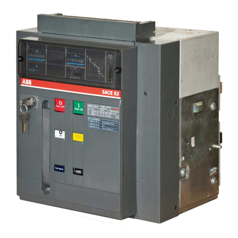
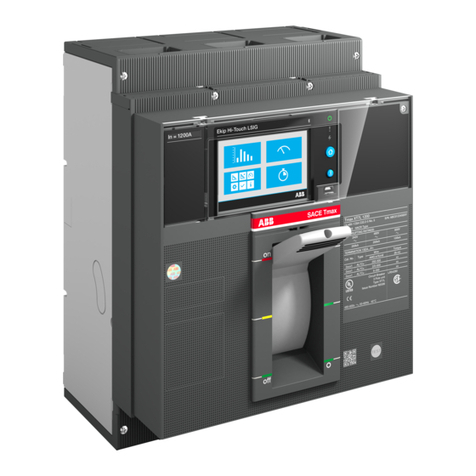
ABB SACE Emax 2 E6.2 manual
Other ABB Circuit Breaker manuals
ABB
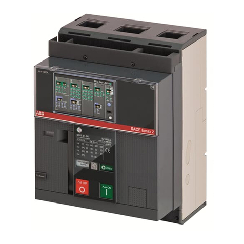
ABB Tmax RC221 User manual
ABB
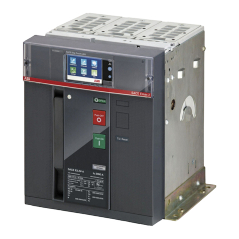
ABB SACE Emax 2 User manual
ABB
ABB SACE Emax 2 User manual
ABB
ABB S 280 UC Series Instruction manual
ABB
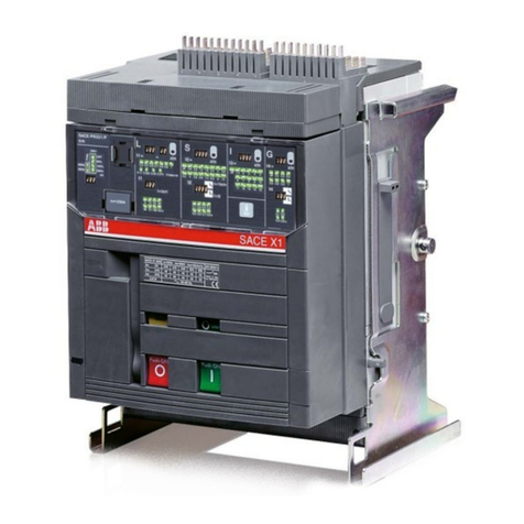
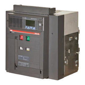
ABB T7-T7M-X1 User guide
ABB
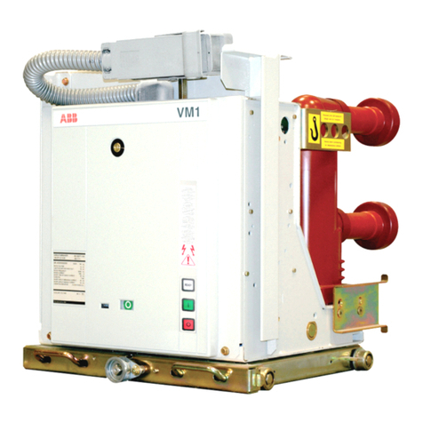
ABB SACE Emax Series Manual
ABB
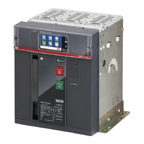
ABB VM1-T User manual
ABB
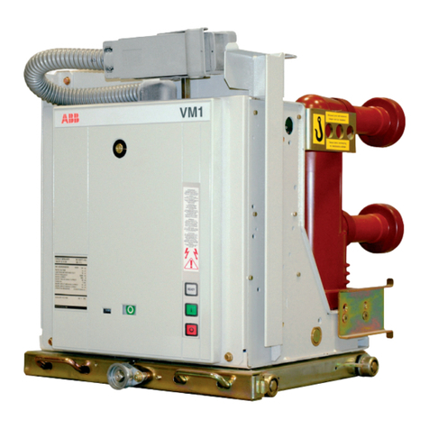
ABB SACE Emax 2 Product manual
ABB
ABB VM1/A/P Quick guide
ABB
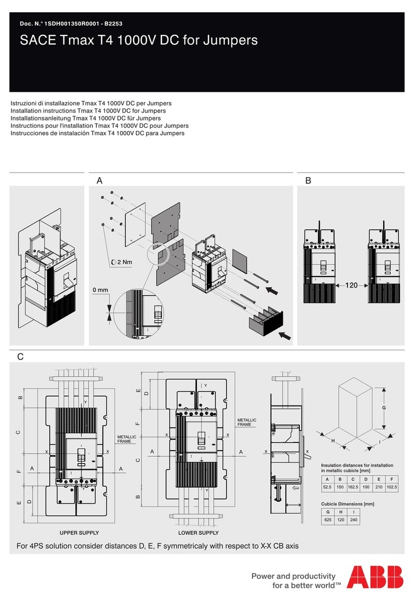
ABB SACE Tmax T4 User manual
ABB
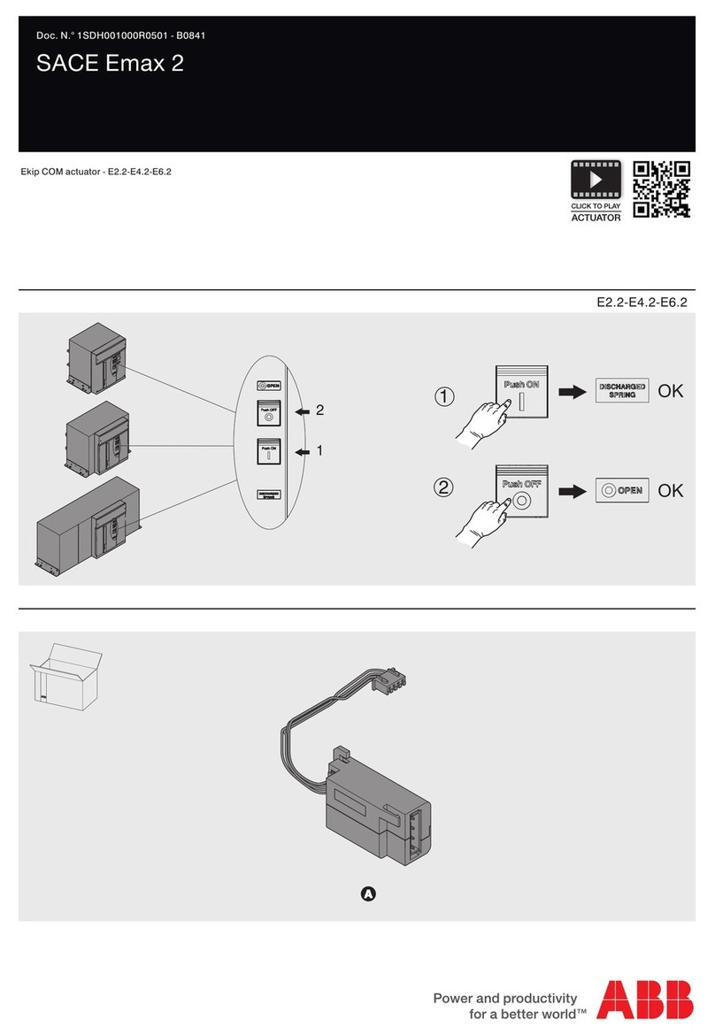
ABB SACE Emax 2 User manual

ABB
ABB SACE Emax 2 User manual

ABB
ABB SACE Emax 2 User manual

ABB
ABB SACE Emax 2 User manual

ABB
ABB SACE Emax 2 User manual
ABB
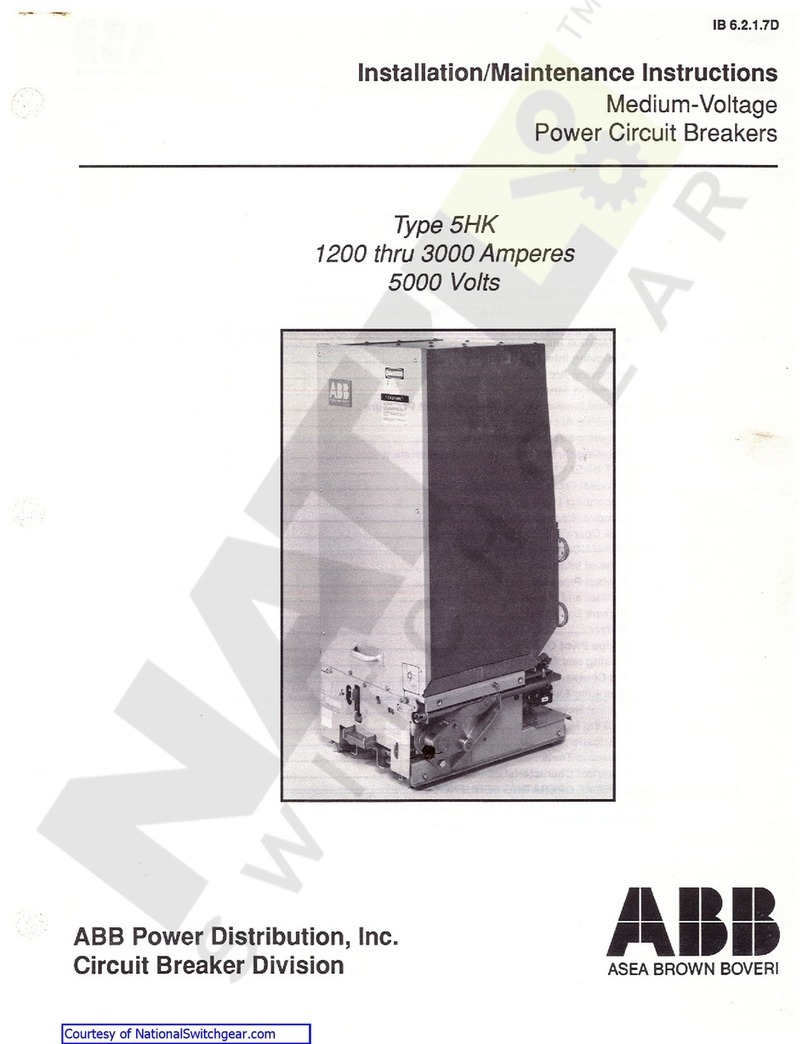
ABB 5HK Series Installation and operating instructions
ABB
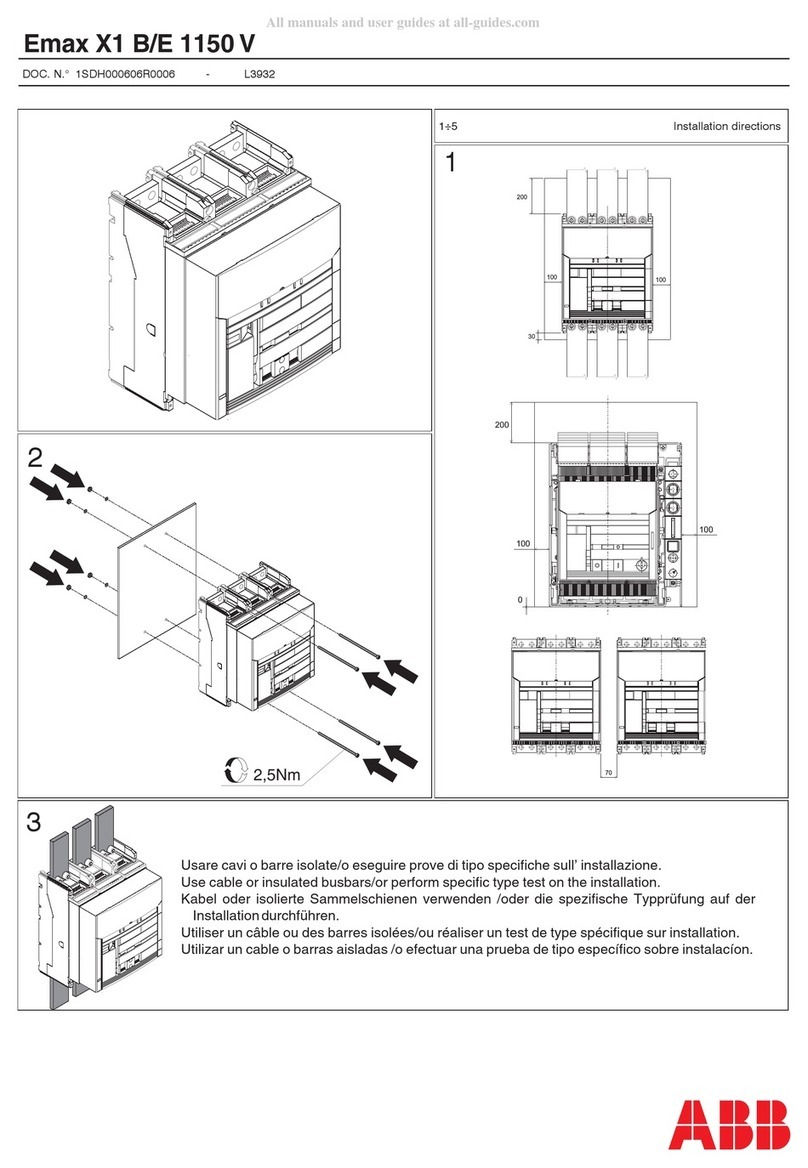
ABB Emax X1 B/E 1150 V User manual
ABB
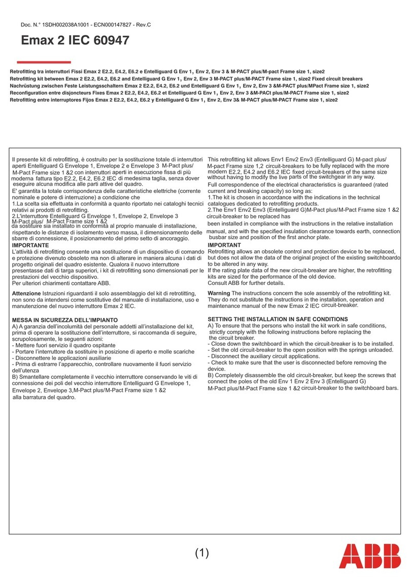
ABB Emax 2 IEC 60947 User manual
ABB
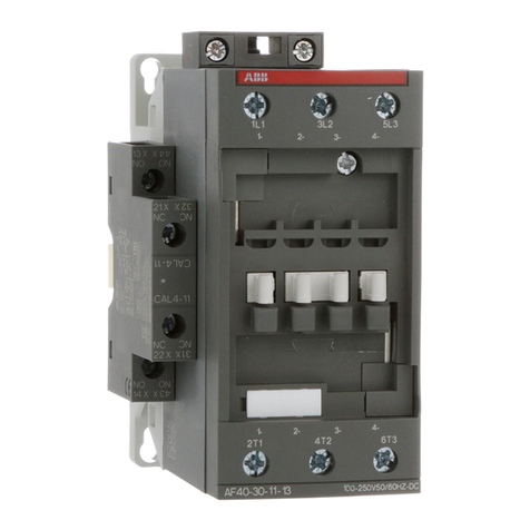
ABB AF40 User manual
ABB
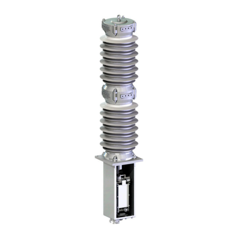
ABB FSK II S + Operating instructions
Popular Circuit Breaker manuals by other brands
Siemens
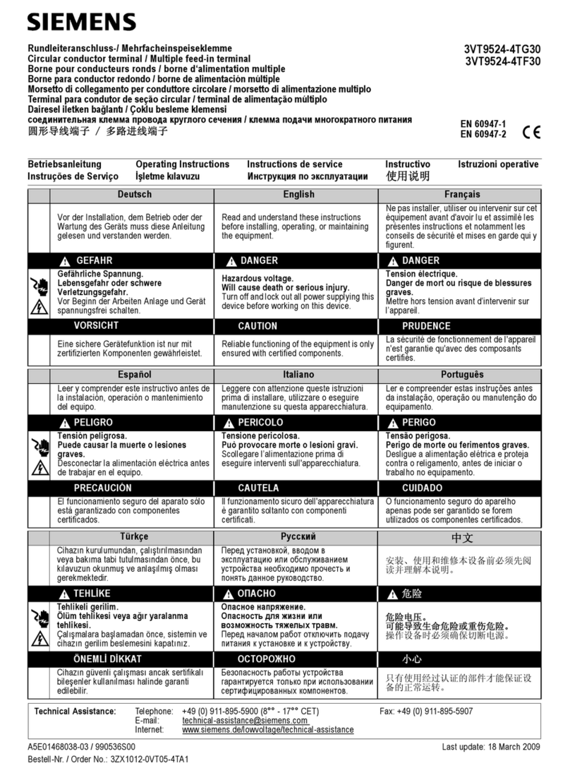
Siemens 3VT9524-4TG30 quick start guide
Acrel
Acrel ASCB1 Series Installation and operation manual

Eaton
Eaton NOVA LBS 15 Installation and operation instructions

Siemens
Siemens SIRIUS 3RV1742 Original operating instructions

WEG
WEG FHU ACW125 installation instructions

TERASAKI
TERASAKI NHP TemBreak PRO P160 Series installation instructions
