Federal SNR48 Installation instructions

E3941
2/10/2020
SNR48, SNR59, SNR77
SN48-3, SN59-3, SN77-3
SN4CD, SN6CD, SN77CD
Self-Contained & Remote Models
INSTALLATION & OPERATION
INSTRUCTIONS
KEEP THIS MANUAL FOR FUTURE REFERENCE
Engineering and technical date are subject to change without notice.
FEDERAL INDUSTRIES PO BOX 290, 215 FEDERAL AVE Belleville, WI 53508
Toll Free (800) 356-4206 Phone (608)424-333 Fax (608) 424-3234

Series ’90 Refrigerated Bakery Page 2
CONTENTS
INTRODUCTION .....................................................................................................4
WARNING LABELS & SAFETY INSTRUCTIONS..............................................5
PRE-INSTALLATION PROCEDURES...................................................................6
Inspection for Shipping Damage ............................................................................................. 6
INSTALLATION INSTRUCTIONS ........................................................................6
Locating the Display Case........................................................................................................ 6
Removing the case from Shipping Skid.................................................................................. 6
Removing Packaging Material ................................................................................................ 7
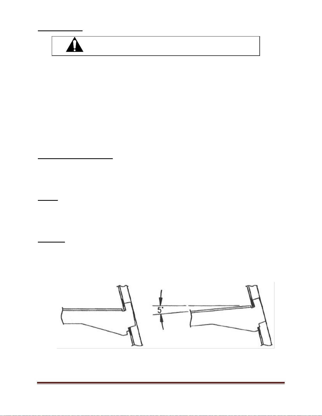
Leveling the Case...................................................................................................................... 7
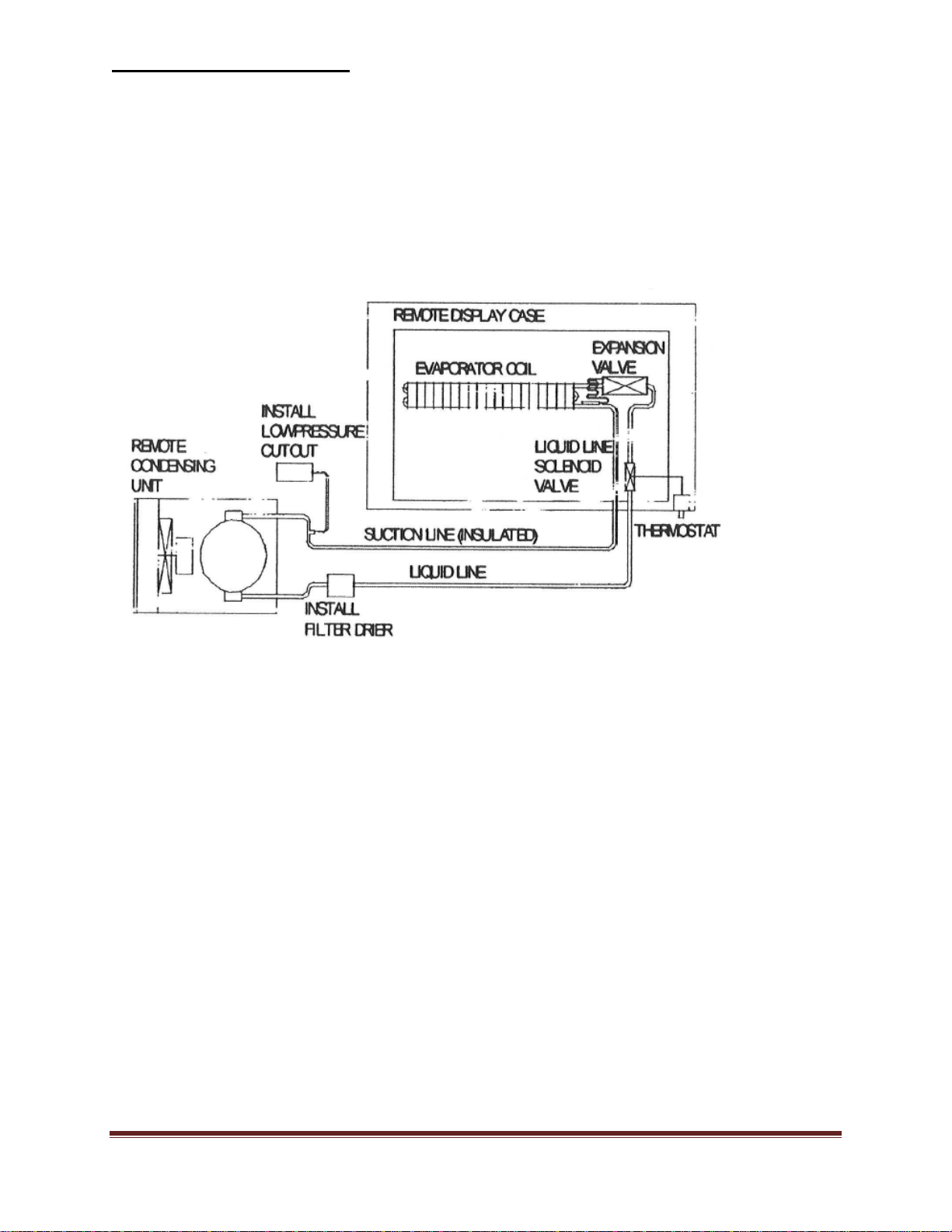
Refrigeration Installation......................................................................................................... 8
Grill Removal............................................................................................................................ 9
Condensate Evaporator............................................................................................................ 9
Lights.......................................................................................................................................... 9
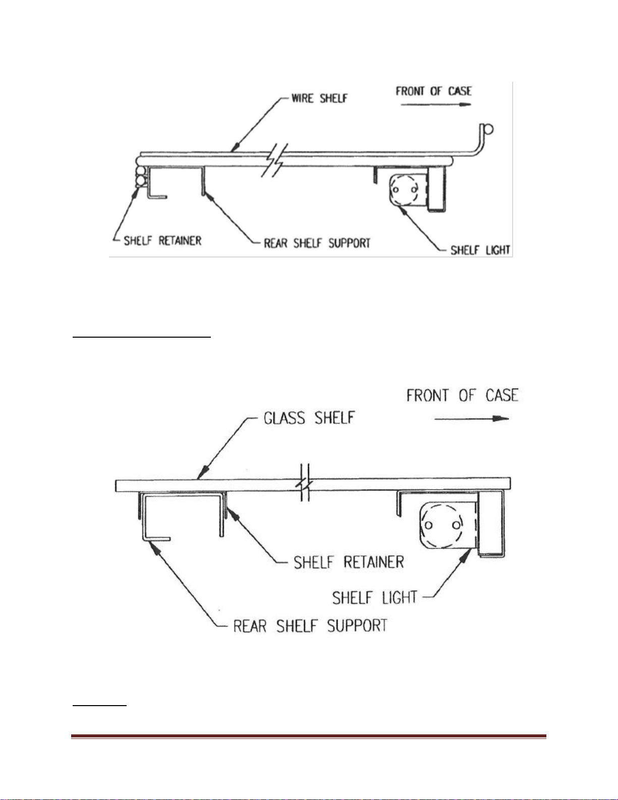
Shelving...................................................................................................................................... 9
Optional Glass Shelves ........................................................................................................... 10
Cleaning................................................................................................................................... 10
ELECTRICAL INFORMATION & GROUNDING...............................................11
OPERATING INSTRUCTIONS.............................................................................12
Initial Start-Up........................................................................................................................ 12
Controls.................................................................................................................................... 12
Doors........................................................................................................................................ 12
Anti-Fogging Fans................................................................................................................... 12
Hinged Front Glass................................................................................................................. 13
Shelves...................................................................................................................................... 14
Light Replacement.................................................................................................................. 15
Placing Product into Case...................................................................................................... 15
Periodic Maintenance............................................................................................................. 15
CLEANING INSTRUCTIONS...............................................................................16
Daily Cleaning......................................................................................................................... 16
Weekly Cleaning..................................................................................................................... 16
Interior Cleaning..................................................................................................................... 17
Exterior Cleaning.................................................................................................................... 17
SERVICE INFORMATION....................................................................................18
Pre-Service Checklist.............................................................................................................. 19
Special Service Situations....................................................................................................... 20
SALE & DISPOSAL ...............................................................................................20
Owner Responsibility ............................................................................................................. 20
REFRIGERATION & ELECTRICAL DATA SELF-CONTAINED:....................21
SNR48SC-2, SNR59SC-2, SNR77SC-2................................................................................. 21
SN48-3SC, SN59-3SC, SN77-3SC.......................................................................................... 22
SN4CD, SN6CD, SN8CD........................................................................................................ 23
REFRIGERATION & ELECTRICAL DATA REMOTE: .....................................24
SNR48R-2, SNR59R-2, SNR77R-2 OBSOLETE 1/1/2012.................................................. 24
SN48R-3R, SN59-3R, SN77-3R OBSOLETE 1/1/2012........................................................ 25
SN4CD-R, SN6CD-R, SN8CD-R OBSOLETE 1/1/2012..................................................... 25
REPLACEMENT PARTS:......................................................................................26
SNR48SC-2, SNR59SC-2 & SNR77SC-2.............................................................................. 26

Series ’90 Refrigerated Bakery Page 3
SN48-3SC-2, SN59-3SC-2, SN77-3SC-2................................................................................ 27
SN4CD, SN6CD, & SN8CD ................................................................................................... 28
WIRING DIAGRAM SELF-CONTAINED: ..........................................................29
WIRING DIAGRAM: SNR48SC-2, SNR59SC-2................................................................ 29
WIRING DIAGRAM: SNR77SC-2....................................................................................... 30
WIRING DIAGRAM: SN48-3SC-2...................................................................................... 31
WIRING DIAGRAM: SN59-3SC-2 & SN77-3SC-2............................................................ 32
WIRING DIAGRAM: SN4CD.............................................................................................. 33
WIRING DIAGRAM: SN6CD.............................................................................................. 34
WIRING DIAGRAM: SN8CD.............................................................................................. 35
WIRING DIAGRAM REMOTE:............................................................................36
WIRING DIAGRAM: SNR48R-2 & SNR59R-2 OBSOLETE 1/1/2012 ........................... 36
WIRING DIAGRAM: SNR77R-2 OBSOLETE1/1/2012.................................................... 37
WIRING DIAGRAM: SN48-3R-2 OBSOLETE1/1/2012 ................................................... 38
WIRING DIAGRAM: SN59-3R-2, SN77-3R-2 OBSOLETE 1/1/2012.............................. 39
WIRING DIAGRAM: SN4CDR OBSOLETE 1/1/2012 ..................................................... 40
WIRING DIAGRAM: SN6CDR OBSOLETE 1/1/2012 ..................................................... 41
WIRING DIAGRAM: SN8CDR OBSOLETE 1/1/2012 ..................................................... 42

Series ’90 Refrigerated Bakery Page 4
NOTICE
Read this manual before installing your case. Keep this manual and refer to it before doing any
service on the equipment. Failure to do so could result in personal injury or damage to the case.
NOTICE
Installation and service of the electrical components in the case must be performed by a licensed
electrician.
The portions of this manual covering electrical components contain technical instructions intended only
for persons qualified to perform electrical work.
DANGER
Improper or faulty hookup of electrical components in the case can result in severe injury or
death.
All electrical wiring hookups must be done in accordance with all applicable local, regional, or
national standards.
INTRODUCTION
Thank you for purchasing a Federal Industries display case. This manual contains
important instructions for installing and servicing the Series ’90 Refrigerated Bakery
Cases. A repair parts list and wiring diagram are also included in the manual. Read all of
these documents carefully before installing or servicing your case.
REGISTRATION & SERIAL NUMBER
It’s important to keep a record of the model and serial number of your merchandiser for warranty
and part identification. Please write them here for your quick reference.
Register your product online! Visit our website at www.federalindustries.com and register
your product today.
Case Model__________________________ Serial Number______________________
We’re here to provide you with the best possible experience with your new product, however, we
cannot cover everything about your merchandiser in this manual, so if you have any additional
questions or issues, please see the SERVICE INFORMATION PAGE to find who you should
contact.

Series ’90 Refrigerated Bakery Page 5
Notice to Employers
You must make sure that everyone who installs, uses, or services your case is thoroughly
familiar with all safety information and procedures.
WARNING LABELS & SAFETY
INSTRUCTIONS
This is the safety-alert symbol. When you see this symbol on your case or in
the manual, be alert to potential for personal injury or damage to your
equipment.
Be sure you understand all the safety messages and always follow recommended
precautions and safe operating practices.
Important safety information is presented in this section and throughout the manual. The
following signal words are used in the warnings and safety messages:
DANGER: Severe injury or death will occur if you ignore the message.
WARNING: Severe injury or death can occur if you ignore the message.
CAUTION: Minor injury or damage to your case can occur if you ignore the message.
NOTICE: This is important installation, operation, or service information. If you
ignore the message, you may damage your case.
The warning and safety labels shown throughout this manual are placed on your Federal
Industries case at the factory. Follow all warning label instructions. If any warning or
safety labels become lost or damaged, call our customer service department at 1(800)356-
4206 for replacements.
This label is located on the back of the display case. This label is located below the display pan.

Series ’90 Refrigerated Bakery Page 6
CAUTION: Do not push against the curved glass, end glass, doors or door frames
when removing the case from the skid or moving the case. Case damage
or glass breakage could result.
This label is located on the back of the display case.
PRE-INSTALLATION PROCEDURES
Inspection for Shipping Damage
You are responsible for filing all freight claims with the delivering truck line. Inspect all
cartons and crates for damage as soon as they arrive. If damage is noted to shipping crates
or cartons or if a shortage is found, note this on the bill of lading (all copies) prior to
signing.
If damage is discovered when the case is uncrated, immediately call the delivering truck line
and follow up the call with a written report indicating concealed damage to your shipment.
Ask for immediate inspection of your concealed damage item. Crating material must be
retained to show the inspector from the truck line.
INSTALLATION INSTRUCTIONS
Locating the Display Case
The case should be located where it is not subjected to the direct rays of the sun, heating
ducts, grills, radiator, or ceiling fans, nor should it be located near open doors or main door
entrances. Also, avoid locations where there is excessive air movement or air disturbances.
The condenser inlet is located at the rear of the case. Do not block this inlet and do not
locate the air inlet near a source of heat.
Removing the case from Shipping Skid
Move the case as near as possible to the final location before removing it from the shipping
skid.
Remove the four (4) bolts that secure the case to the skid. Do not remove the shipping
brackets from the case. The brackets are intended to be used as hand grips for locating the
case.
Remove the brackets when the case is in the final location

Series ’90 Refrigerated Bakery Page 7
Removing Packaging Material
Remove the brackets that held the case to the shipping skid.
Remove the plastic ties that hold the wire shelves and shelf brackets in place.
Remove the shipping tape that secures the doors and lift-up glass. If it is necessary to
remove tape residue from plastic materials, use cleaning compounds recommended in the
cleaning section of this manual.
Leveling the Case
The case must be level for proper drainage of defrost condensate to the condensate
evaporator.
Four (4) leg levelers are provided for leveling the case. The leg levelers can be turn in and
the case can be placed with the base frame on the floor.
The leveled case must be sealed to the floor using and NSF listed Sealant.

Series ’90 Refrigerated Bakery Page 8
Refrigeration Installation
Self-Contained Models
The self-contained models are shipped from the factory with a completely operational
refrigeration system and require no modifications or adjustments of the system upon
installation.
Remote Models (Obsolete as of 1/1/2012)
The remote models are designed to use 134A refrigerant and shipped from the factory with
the evaporator coil, expansion valve, refrigerant solenoid valve, and thermostat. The
thermostat senses interior case temperature and opens and closes the refrigerant solenoid
valve as needed to maintain proper case temperatures. The condensing unit is optionally
supplied from the factory for remote location installation.
A. Mount condensing unit indoors as close to the remote display as practical. The
refrigeration line should be as short as possible.
B. All refrigeration and/or electrical materials between the condensing unit and display
case are to be supplied by installing contractor.
C. Route properly sized and designed refrigeration lines from the condensing unit to the
cabinet. Horizontal suction lines should be pitched downward towards the condensing
unit and least ½” per 10’ run to aid the oil drainage. A “P” trap must be installed in the
suction line at the foot of every riser to insure oil return. Dry nitrogen should be used to
flow through tubing while brazing refrigeration lines.
D. Suction line must be insulated the entire length with Armaflex (or equivalent). Do not
run liquid line inside insulation with suction line.
E. The filter drier, sight glass, and low-pressure control are not furnished with remote
display case models. The recommended low pressure setting for R134A refrigerant is
32# cut in and 0# cut-out.
F. Leak check condensing unit, cabinet, and all connecting tubing. Cabinet and
condensing unit tubing should be checked to insure no leaks occurred during shipping
or from rough handling. Make certain all refrigeration valves are opened and evacuate
system to 500 microns. Charge the system with refrigerant type specified on the data
plates.

Series ’90 Refrigerated Bakery Page 9
DANGER: Electric shock hazard. Do not operate unit with
panels removed.
Grill Removal
The front of the case has a removable base panel to access the anti-fogging fans and the
front leg levelers from inside of the case. Normally it is not necessary to remove the panel to
install the case. This panel must be in place for proper operation of the case.
There are two (2) removable panels on the back of the case. The left side panel allows
access to the light ballasts, the pullout condensing unit, and the field wiring connection box.
Remove this panel to make field wiring connections.
The right side panels has the thermometer, power switch, light switch, and thermostat
mounted to it. Removing this panel allows access to the terminal board, branch circuit fuse,
condensate evaporator, and compressor service ports. Normally it is not necessary to
remove this panel to install the case.
Condensate Evaporator
This case is furnished with an electric condensate evaporator. Plumbing connections are
not required.
The condensate evaporator is located behind the control panel box and is accessible from
the rear of the case.
Lights
Make certain that the light cord plugs are completely inserted into the sockets or arcing
may result causing damage to the plugs and sockets.
The ballasts used on this case allow removal of one or more shelf lights without affecting the
remaining lights.
Shelving
Remove both rear doors from the track by lifting them upward until the bottom edge clears
the lower door track and then outward.
Lift up the front glass to the fully open position.
Put the shelf support assembly in the desired shelf standard slots.
Plug the shelf light cords in the appropriate light socket. Make certain that the light cords
are completely inserted into the sockets or arcing may result causing damage to the plugs
and sockets.

Series ’90 Refrigerated Bakery Page 10
Put the wire shelves on the rear shelf support assembly as shown. Push the bar on the
bottom of the wire shelf into the shelf retainer clip on the shelf support assembly. If the
shelf is not in the proper position, it may disrupt the air flow in the case and cause product
loss.
Close the front glass and reinstall both rear doors.
Optional Glass Shelves
Put the glass shelves on the rear shelf support and shelf light housing as shown. The shelf
retainer should sit over the rear shelf support. If the shelf is not in the proper position, it
may disrupt the air flow in the case and could cause product loss.
Reinstall both rear doors.
Cleaning
For initial set up, clean the case as outlined in the weekly cleaning section.

Series ’90 Refrigerated Bakery Page 11
DANGER: Improper or faulty hookup of electrical
components in the display case can result in severe
injury or death.
ELECTRICAL INFORMATION &
GROUNDING
THE CASE MUST BE GROUNDED
All case electrical connections must be performed by a licensed electrician.
All electrical wiring hookups must be done in accordance with all applicable local, regional,
or national electrical standards.
A separate circuit for each display case is recommended to prevent other appliances on the
same circuit from overloading the circuit and causing malfunction.
The electrical service must be grounded upon installation.
This unit is designed for permanent connection to a power source. See the electrical data
plate located next to electrical junction box for proper circuit size and wire ampacity.
A 7/8” diameter hole is provided in the back of the case for field wiring connections. An
access hole is also provide in the unit base for running power supply up through the floor.
See diagram below.

Series ’90 Refrigerated Bakery Page 12
OPERATING INSTRUCTIONS
Initial Start-Up
After all the checks outlined in the installation section of this manual have been made, the
case is ready to be put into service. The service valves on the refrigeration system are back
seated when the unit leaves the factory.
Controls
Power Switch
This switch controls power to the entire case. It is labeled with on and off positions
Light Switch
This switch controls the power to the lighting circuit. The switch rocker is red in the “on”
position, black in the “off” position.
Temperature Control
This controls the case temperature by cycling the compressor/condensing unit. It has an
“off” position and numbered positions 1 through 9. The coldest setting is 9. Set this control
at the smallest number while maintaining desired case temperature.
Thermometer
This is a solar powered device. It changes the temperature display approximately every 10
seconds.
Doors
The doors can be removed by lifting the door up until the bottom clears the bottom track.
Clean the door track frequently for easy door operation. A very light film of lubricant,
such as PAM, will help the doors slide easily.
Anti-Fogging Fans
Two fans are mounted in the base of the unit to blow arm air from the refrigeration system
over the curved glass to prevent fogging. The warm air is vented through the slots in the
glass handle. Do not block these vents or the front glass will fog. These fans run
continuously when the power switch is on.

Series ’90 Refrigerated Bakery Page 13
CAUTION: OPERATION OF THE LIFT-UP GLASS IS
TO BE DONE BY TRAINED STORE
PERSONNEL ONLY. THIS CASE IS NOT
INTENDED TO BE USED AS A SELF-SERVE
UNIT. DO NOT ALLOW CUSTOMERS TO
OPERATE LIFT-UP GLASS.
Hinged Front Glass
The front glass hinges up for easy cleaning of the case interior. Pneumatic cylinders assist
in lifting the glass. The glass will hold in any position beyond approximately the first 20” of
travel. In the first 20” of travel, the glass will gently close. See diagram below:
The hinged glass mechanism will give years of reliable operation in normal usage. Service
on the lift mechanism is required if…
-The glass becomes difficult to open.
-The glass does not hold in the open position.
-The glass closes fast.
Consult factory if service is required.

Series ’90 Refrigerated Bakery Page 14
Shelves
The shelves are adjustable up and down in 2” increments. To reposition shelves:
1. Turn the shelf lights off.
2. Unplug the shelf light cord.
3. Remove all shelves from the shelf supports.
4. Grasp the shelf support at each end.
5. Tip the front of the shelf support up until it can be removed from the shelf
standard.
6. Reposition the shelf as desired.
The shelves can be installed horizontally or slanted at 5° to change the shelf slant:
1. Remove the shelves from the shelf support.
2. Grasp the shelf support at each end.
3. Lift the shelf support up at the back until the brackets can be repositioned in the
shelf standard slots. See diagram below:

Series ’90 Refrigerated Bakery Page 15
Light Replacement
The light fixtures use a spring-loaded socket on one end. To remove a light, push the bulb
toward the spring-loaded socket until the opposite end drops out of the socket.
The bulbs are furnished with plastic safety light shields. Make certain the light shields are
always in place to safeguard against bulb breakage.
When replacing lights, use direct equivalents to the original bulbs.
Placing Product into Case
Do not overhang the wire shelves with product or display pans. Overhanging the shelves
will block the refrigerated air flow and could cause product loss.
Do not block the slots along the front or rear of the case display floor.
CASE SHOULD BE STOCKED WITH PRE-CHILLED PRODUCT ONLY.
The display pans are removable for cleaning and can become dislodged in shipment. To
ensure proper air flow and performance of the case, make sure that the display pans are
positioned as shown. Check that the pans are installed properly before placing product on
the display pans.
Periodic Maintenance
Cleaning Condenser Coil
Disconnect power to the unit.
Remove the rear grill and vacuum the front surface of the condenser coil. This
should be done everyone to two months as necessary.

Series ’90 Refrigerated Bakery Page 16
NOTICE: Avoid splashing or soaking any electrical components
with water to prevent electrical damage to the case.
NOTICE: Avoid splashing or soaking any electrical components
with water to prevent electrical damage to the case.
NOTICE: Shut off lights and power switches and remove all
product from case. Allow enough time for the unit to
reach room temperature before proceeding with
cleaning.
CLEANING INSTRUCTIONS
Daily Cleaning
The case should be cleaned thoroughly, as described in the weekly cleaning section, before it
is used for the first time.
Note: For major spills or foreign material buildup use complete weekly cleaning
instruction.
1. Clean all foreign materials from the door opening.
2. Wipe complete interior of case using a damp cloth.
3. The glass can be cleaned with common window cleaners. The remaining exterior
surface should be wiped down using any ammoniated cleansers or soapy warm water.
Note: Detergents are not recommended.
Weekly Cleaning
This procedure is recommended on a weekly basis. It may need to be performed more often
if necessary, to maintain a clean, sanitary case. The case should be cleaned to this
procedure before using the first time.
NOTICE: Shut off lights and power switches and remove all
product from case. Allow enough time for the unit to
reach room temperature before proceeding with
cleaning.

Series ’90 Refrigerated Bakery Page 17
Interior Cleaning
1. Remove rear doors from track by lifting door upward until the bottom of the door
clears the lower door track and then outward. Remove the inner door in the same
manner.
2. Lift up the front glass to the fully open position.
3. Remove all shelves from the case.
4. Unplug the shelf lights and lift the shelf support assembly out of the shelf standard slots.
5. Remove the two (2) thumb screws holding the shelf standard to the side wall and take
the shelf standard out of the case.
6. Lift the display pans up and take them out of the case.
7. Clean the entire interior of the case using warm soapy water. Wipe off all soapy water
with a damp cloth and allow to dry.
Note: Depending on the amount and spillage of foreign material, some fasteners may have to
be removed and parts disassembled to allow proper cleaning of the unit.
8. Clean all shelves, shelf support assemblies, shelf standards, and display pans using
warm soapy water and a brush. Rinse thoroughly and allow to dry.
9. Clean all foreign material from inner and outer rear door tracks using warm soapy
water and a brush. Apply a light film of lubricant, such as PAM, to make the doors
operate smoother.
10. Clean both sides of the doors and interior of the front glass using any common window
cleaner.
11. Reassemble the case in reverse order starting with step 6.
Exterior Cleaning
1. Clean the front glass using any common window cleaner.
2. The exterior surfaces should be wiped down using any ammoniated cleansers or warm
soapy water.
Plastic exterior surfaces can be cleaned with any ammoniated household cleaner. Stains
can be removed by scrubbing with TRIALENE Soap, ETHYL CELLOSOLVE,
CARBONA, or similar solvent base cleaning fluids. The surfaces must be thoroughly rinsed
with warm water after using solvent based cleaners.

Series ’90 Refrigerated Bakery Page 18
CAUTION
POWER BEFORE
RISK OF ELECTRIC
SHOCK DISCONNECT
91-12340
SERVICING UNIT.
SERVICE INFORMATION
Before any service work is performed
on the case, make sure all power is
disconnected to the case.
To find a service company in your area, please visit our website at
www.federalindustries.com. There you can also find self-service tools to
help you get the answers you need faster!
For Warranty Service Requests & ALL Technical Support please contact:
- Phone: (800) 356-4206 and choose the Tech Support/Warranty Option
- Email: [email protected]
For Warranty Compressors please contact the Parts Department:
- Phone: (800) 356-4206 and choose the Warranty Parts Option
- Email: [email protected]
Federal Industries has partnered with Parts Town for ALL Non-Warranty Part
Identification, Pricing, Lead Times, Orders & Freight Quotes. Please contact
Parts Town directly if you need parts:
- Website: PartsTown.com
- Phone: 833-809-8188

Series ’90 Refrigerated Bakery Page 19
CAUTION: Before servicing case turn off power at the
main breaker or fuse box.
Pre-Service Checklist
You may avoid the cost and inconvenience of an unnecessary service call by first reviewing
this checklist of frequently encountered situations that can cause unsatisfactory case
performance.
1. Case Does Not Operate
a. Check for disconnected power supply.
b. Check for tripped breaker or blown fuse.
c. Check that the power switch and thermostat are not “off”
2. Lights Do Not Operate
a. Check that the light switch is on.
b. Be sure light is properly seated in the sockets.
c. Check that light cord(s) are tight in the sockets.
3. Case Temperature Too Warm
a. Check that the cold air inlet and outlet slots are not blocked.
b. Be sure front glass is closed tightly and back doors are closed.
c. Check for a blocked or dirty condenser coil.
d. Check cold air flow. Lack of adequate cold air flow could be a defective evaporator fan
or blocked evaporator coil. Check that paper or foreign material is not blocking
evaporator. If the evaporator coil is blocked due to excessive frost, turn the thermostat
knob to the “off” position for approximately one hour to defrost. Excessive frost will
build-up if the case is operated with the door open or ajar.
4. Glass Fogging
a. Check room ambient- Case is designed to operate in an environment not to exceed 75F
and 55% relative humidity.
b. Check case temperature- Case is designed to operate between 38F and 42F.
c. Check that nothing is blocking the warm air vents in the glass handle. Check that warm
air is being blown evenly across the front glass surface. If the air is not blowing or is not
blown evenly, service is required.
d. Check that the air flow is not being disturbed by a nearby fan or air duct.
e. Check that noting is placed on top of the glass case.

Series ’90 Refrigerated Bakery Page 20
Special Service Situations
There are rare occasions when the refrigerant charge must be evacuated from a case in
order to perform service work. In those situations, Federal Industries recommends that the
refrigerant charge be evacuated into a recovery system to prevent the possibility of
hydrofluorocarbons (HFC’s) from being released into the atmosphere. The release of
HFC’s into the atmosphere is a potential source of global warming.
If moisture or liquid is observed around or under a Federal Industries case, an immediate
investigation should be made by qualified personnel to determine the source of moisture or
liquid. The investigation made should determine if the case is malfunctioning or if there is a
simple housekeeping problem.
Moisture or liquid around or under a case is a potential slip/fall hazard for persons walking
by or working in the general area of the case. Any case malfunction or housekeeping
problem that creates a slip/fall hazard around or under a case should be corrected
immediately.
SALE & DISPOSAL
Owner Responsibility
If you sell or give away your Federal Industries case you must make sure that all safety
labels and the Installation-Service Manual are included with it. If you need replacement
labels or manuals, Federal Industries will provide them free of charge. Contact the
customer service department at Federal Industries at (800)356-4206.
The customer service department at Federal Industries should be contacted at the time of
sale or disposal of your case so records may be kept of its new location.
If you sell or give away your Federal Industries case and you evacuate the refrigerant
charge before shipment, Federal Industries recommends that the charge be evacuated into a
recovery system to prevent the possibility of HFC’s from being released into the
atmosphere. The release of these HFC’s is a potential source of global warming.
This manual suits for next models
27
Table of contents
Other Federal Display Case manuals

Federal
Federal FCC-4 Installation instructions

Federal
Federal RSSM360 Installation instructions

Federal
Federal ITD48 Installation instructions

Federal
Federal ECGR50 Installation instructions

Federal
Federal CRR4828 Installation instructions

Federal
Federal SN48 Installation instructions

Federal
Federal SNR482C-2 User manual