Excillum MetalJet D2+ User manual

Revision 19, November 2016
MetalJet D2+ Operating manual

METALJET D2+
Revision 19, November 2016 ii
Disclaimer
The information provided herein is supplied under a non-exclusive license authorizing its use solely for and in
conjunction with Excillum Aktiebolag’s (Excillum) products. Although diligent care has been used to ensure that
the information is accurate, nothing contained herein can be construed to imply any representation or warranty
as to the accuracy or completeness of this information. Excillum reserves the right to alter this information at
our own discretion at anytime. The warranty and product documentation remains valid as long as the customer
does not make any changes to the product.
Acknowledgement
All registered and unregistered trademarks, domain names and copyrights herein are the property of their
respective owners.
Excillum, MetalJet, MetalJet D1, MetalJet D2 and MetalJet D2+ are registered trademarks or trademarks of
Excillum AB. Excillum
’
s MetalJet sources are protected by several patents including, but not limited to, US
Patents No. US 6 711 233, US8 170 179, US 8 681 943, US 8 837 679, US 9 171 693, US 9 245 707, and Chinese
Patents No. CN 01 816396.3, ZL200780026317.0, ZL200980155094.7, ZL 200980158566.4, ZL 201080070417.5,
and other corresponding national patents and patent applications pending.
Copyright notice
© Excillum Aktiebolag 2016, Stockholm, Sweden. All rights reserved worldwide.
Contact information
The MetalJet D2+ source described in this operating manual has been produced by Excillum Aktiebolag. Excillum
may be contacted in several different ways.
Mailing and visiting address
Excillum Aktiebolag
Torshamnsgatan 35
SE-164 40 Kista
SWEDEN
Phone
+46 (0)8-750 96 60
Fax
+46 (0)8-750 96 65
E-mail
Website
www.excillum.com

METALJET D2+
Revision 19, November 2016 iii
Please fill in the serial numbers and the manufacturing year for the sub-assembly units of your MetalJet D2+ x-
ray source in the table below, and have them readily available when contacting Excillum for assistance,
additional information, or purchase of spare parts.
The serial numbers and the manufacturing year may be found on the identification tag on the rear of each sub-
assembly unit, close to the electrical power connector.
System article number: G-020-0037 rev 02
Sub-assembly unit
Article number
Serial number
Manufacturing year
Electron gun/x-ray head
G-020-0020
EXH-
Pump box
G-035-0033
PBO-
X-ray system controller
G-010-0000
SCO-
X-ray high-voltage controller
G-010-0001
HVC-

METALJET D2+ TABLE OF CONTENTS
Revision 19, November 2016 iv
Table of Contents
1INTRODUCTION.............................................................................................................................1-1
1.1 Validity................................................................................................................................................ 1-1
1.2 Instructions and conventions ............................................................................................................. 1-1
1.3 Product information ........................................................................................................................... 1-2
1.3.1 Product identification..................................................................................................................... 1-2
1.3.2 Design and function ....................................................................................................................... 1-2
1.3.2.1 Liquid-metal circulation loop................................................................................................. 1-2
1.3.2.2 Electron gun/x-ray head........................................................................................................ 1-2
1.3.3 X-ray output options ...................................................................................................................... 1-6
1.3.3.1 With x-ray shutter ................................................................................................................. 1-7
1.3.3.2 Without x-ray shutter using standard exit window............................................................... 1-8
1.3.3.3 Without x-ray shutter using increased cone angle exit window ........................................... 1-9
2SAFETY..........................................................................................................................................2-1
2.1 Safety precautions.............................................................................................................................. 2-1
2.1.1 Qualified personnel........................................................................................................................ 2-1
2.1.2 Partly completed machinery .......................................................................................................... 2-1
2.1.3 Operating manual .......................................................................................................................... 2-1
2.1.4 X-ray radiation................................................................................................................................ 2-2
2.1.5 Electricity and high voltage ............................................................................................................ 2-2
2.1.6 High pressure ................................................................................................................................. 2-3
2.1.7 Heat................................................................................................................................................ 2-4
2.1.8 Magnetic fields............................................................................................................................... 2-4
2.1.9 Poisoning hazard ............................................................................................................................ 2-5
2.2 Proper use .......................................................................................................................................... 2-6
2.3 Improper use ...................................................................................................................................... 2-6
3TRANSPORT AND STORAGE ...........................................................................................................3-1
3.1 Transport ............................................................................................................................................ 3-1
3.1.1 Lifting.............................................................................................................................................. 3-1
3.2 Storage................................................................................................................................................ 3-2
4INSTALLATION...............................................................................................................................4-1
4.1 Initial Installation Checklist................................................................................................................. 4-1
4.2 Unpacking........................................................................................................................................... 4-2
4.3 Setting up the MetalJet D2+ source ................................................................................................... 4-2

METALJET D2+ TABLE OF CONTENTS
Revision 19, November 2016 v
4.3.1 Mounting of sub-assembly units.................................................................................................... 4-2
4.3.2 Connecting tubing and cables ........................................................................................................ 4-8
4.3.2.1 Tighten inlet and outlet check valve housings ...................................................................... 4-8
4.3.2.2 Flex-hose assembly and jet-exit port..................................................................................... 4-8
4.3.2.3 Cooling water supply and return........................................................................................... 4-9
4.3.2.4 High-pressure tubing and nozzle assembly ......................................................................... 4-13
4.3.2.5 Vacuum hose ....................................................................................................................... 4-13
4.3.2.6 Cooling water ...................................................................................................................... 4-14
4.3.2.7 Interconnecting cables ........................................................................................................ 4-15
4.3.2.8 MetalJet D2+ 70 kV.............................................................................................................. 4-16
4.3.2.9 MetalJet D2+ 160 kV............................................................................................................ 4-19
4.3.2.10 Mains supply........................................................................................................................ 4-23
4.4 Safety system.................................................................................................................................... 4-25
4.4.1 High voltage controller................................................................................................................. 4-25
4.4.2 Electron gun ................................................................................................................................. 4-25
4.5 Operating conditions ........................................................................................................................ 4-27
4.5.1 Ambient conditions...................................................................................................................... 4-27
4.5.2 Ventilation.................................................................................................................................... 4-27
4.5.3 Cooling water ............................................................................................................................... 4-27
4.6 System integration............................................................................................................................ 4-28
4.6.1 System accessibility...................................................................................................................... 4-28
4.6.2 Network connectivity................................................................................................................... 4-30
5OPERATION...................................................................................................................................5-1
5.1 Introductory notes on source operation ............................................................................................ 5-1
5.1.1 Starting jet pump ........................................................................................................................... 5-1
5.1.2 Leave MetalJet D2+ system in On or Ready................................................................................... 5-1
5.1.3 Expected time between service ..................................................................................................... 5-1
5.1.4 Electron beam power vs. spot size................................................................................................. 5-2
5.2 Starting the MetalJet D2+ system ...................................................................................................... 5-3
5.3 Capabilities of the software................................................................................................................ 5-4
5.4 Starting the software and GUI............................................................................................................ 5-4
5.4.1 GUI layout ...................................................................................................................................... 5-6
5.5 The states of the software.................................................................................................................. 5-6
5.5.1 Standard states .............................................................................................................................. 5-6
5.5.2 Advanced states ............................................................................................................................. 5-7
5.5.3 State indicators .............................................................................................................................. 5-8

METALJET D2+ TABLE OF CONTENTS
Revision 19, November 2016 vi
5.6 User levels .......................................................................................................................................... 5-8
5.7 Error messages ................................................................................................................................... 5-8
5.8 Parametrization .................................................................................................................................. 5-9
5.8.1 Prepare system for parametrization .............................................................................................. 5-9
5.8.2 Align electron beam to optical axis .............................................................................................. 5-10
5.8.3 Determine jet size and position ................................................................................................... 5-10
5.8.4 Characterize focus lens and verify jet stability............................................................................. 5-11
5.8.5 Characterize linefocus coils.......................................................................................................... 5-12
5.9 Set emission power and spot size..................................................................................................... 5-13
5.9.1 Recalibrate spot size .................................................................................................................... 5-14
5.9.2 Validate spot size ......................................................................................................................... 5-14
5.10 Normal operation ............................................................................................................................. 5-14
5.10.1 Turning on x-ray generation .................................................................................................... 5-14
5.10.2 Change emission power and spot size..................................................................................... 5-14
5.10.3 Turning off x-ray generation.................................................................................................... 5-14
5.10.4 Turning off the MetalJet D2+ source ....................................................................................... 5-14
5.11 System Settings................................................................................................................................. 5-16
5.12 Software API ..................................................................................................................................... 5-17
6MAINTENANCE AND SERVICE ........................................................................................................6-1
6.1 Vacuum system................................................................................................................................... 6-2
6.1.1 Roughing pump .............................................................................................................................. 6-2
6.1.2 Turbopump..................................................................................................................................... 6-2
6.2 Jet system ........................................................................................................................................... 6-2
6.2.1 Jet pump lubricants........................................................................................................................ 6-2
6.2.2 Jet pump diaphragm ...................................................................................................................... 6-3
6.2.3 Jet pump check valves.................................................................................................................... 6-3
6.2.4 Nozzle assembly............................................................................................................................. 6-4
6.2.5 Particle filter................................................................................................................................... 6-6
6.2.6 Exit window.................................................................................................................................... 6-6
6.2.7 Liquid metal spillage....................................................................................................................... 6-7
6.3 Electron gun........................................................................................................................................ 6-7
6.3.1 Cathode assembly .......................................................................................................................... 6-7
6.4 Climate system ................................................................................................................................... 6-9
6.4.1 Fan filters........................................................................................................................................ 6-9
6.4.2 Cooling water ................................................................................................................................. 6-9
7SHUTDOWN ..................................................................................................................................7-1

METALJET D2+ TABLE OF CONTENTS
Revision 19, November 2016 vii
7.1 Shutting down for shorter periods ..................................................................................................... 7-1
7.2 Shutting down for longer periods....................................................................................................... 7-1
7.3 Restarting after longer shutdown ...................................................................................................... 7-1
7.4 Disposal .............................................................................................................................................. 7-1
8MALFUNCTION AND TROUBLESHOOTING ......................................................................................8-1
9CUSTOMER SUPPORT ....................................................................................................................9-1
9.1 System log files ................................................................................................................................... 9-1
9.2 Remote support.................................................................................................................................. 9-2
10 SPARE PARTS...............................................................................................................................10-1
11 TECHNICAL DATA ........................................................................................................................11-1
METALJET D2+ INTRODUCTION
Revision 19, November 2016 Page 1-1
1INTRODUCTION
1.1 Validity
This operating manual is for customers of Excillum. It describes the functioning of the MetalJet D2+ source and
provides the most important information for safe use of the unit. The description follows applicable EU
guidelines. Up-to-date operating instructions may be obtained by contacting Excillum, see page ii for contact
information.
1.2 Instructions and conventions
The safety instructions in this operating manual are the result of a risk assessment in accordance with SS EN
12100:2010 (Safety of Machinery - General principles for design - Risk assessment and risk reduction) formerly
SS-EN ISO 14121 (Safety of Machinery –Risk Assessment)).
In this document, the following hazard levels and information are considered:
DANGER
Immediate danger: Death or very severe injuries may occur.
WARNING/ATTENTION
Possible danger: Severe injuries may occur.
CAUTION
Possible danger: Medium to slight injuries may occur.
NOTE
Command or note: Command to perform an action or information about properties. If ignored, this may
result in damage to the product.

METALJET D2+ INTRODUCTION
Revision 19, November 2016 Page 1-2
1.3 Product information
1.3.1 Product identification
To correctly identify the product when communicating with Excillum, always provide the following information
from the identification tag(s):
Model number
Article number
Serial number
Manufacturing year
Anode alloy
The identification tag on each of the four sub-assembly units (see table below) is located on its backside, close
to the electrical power connector.
The article number of this MetalJet D2+ source is G-020-0037. The x-ray source consists of the following four
sub-assembly units.
Sub-assembly unit
Article number
Electron gun/x-ray head
G-020-0020
Pump box
G-035-0033
X-ray system controller
G-010-0000
X-ray high-voltage controller
G-010-0001
1.3.2 Design and function
The MetalJet D2+ x-ray source is based on a metal-jet anode. It is not a stand-alone x-ray source, but a
component in a complete x-ray system (for more information, see Section 2.1).
Basically, the MetalJet D2+ source consists of a recirculating metal-jet loop and an electron gun, as well as
electronics modules for operation control. The electron gun generates an electron beam, which strikes the
metal jet and produces x-rays. This x-ray source is suitable for use in any x-ray application where increased x-
ray source brightness is desired. Increased source brightness can be used in order to decease the exposure
time or increase the resolution of the x-ray image.
1.3.2.1 Liquid-metal circulation loop
The jet pump displaces liquid metal from the reservoir in the low-pressure flex-hose assembly to the high-
pressure side. The pressure in the high-pressure tubing is stabilized by a pulsation dampener. When the liquid
metal reaches the nozzle assembly, a metal jet is ejected. This metal jet is the target for the electron beam
generated in the electron gun. After interaction with the electron beam, the metal jet ends up in the reservoir
in the low-pressure flex-hose assembly, and a closed circulation loop is completed.
1.3.2.2 Electron gun/x-ray head
A potential difference between the cathode and the plate with the anode hole generates an electric field. The
cathode is heated in order to emit electrons into the electric field. When free electrons enter the electric field
they are accelerated towards the plate with the anode hole. The electron beam passes through the anode hole
into the flight tube. The electron optics and the focusing lens manipulate the electron beam in order to focus it
onto the metal jet. When the electron beam strikes the metal jet x-rays are produced and emitted through the
x-ray window.
METALJET D2+ INTRODUCTION
Revision 19, November 2016 Page 1-3
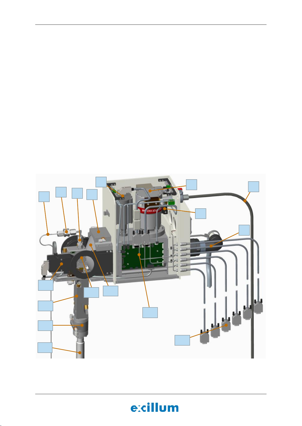
The electron gun/x-ray head consists of the following parts, see Figure 1-1 below:
1. High-pressure tubing
2. Particle filter
3. Nozzle assembly
4. Lens cooling block
5. High-vacuum gauge
6. High-vacuum pump (turbopump)
7. Ventilation valve
8. Fore-vacuum hose
9. High-voltage cable connected to high-voltage feedthrough
10. Interconnecting cables
11. X-ray head PCB (cross connect board)
12. Electron optics
13. Exit window (not visible, it is underneath the shutter)
14. Flex-hose assembly
15. Jet brake
16. Upper cooling block
17. Shutter
Figure 1-1. The main components of the electron gun/x-ray head.
1
2
3
8
7
9
6
5
4
10
0
11
0
12
0
13
0
14
0
16
17
0
15
0

METALJET D2+ INTRODUCTION
Revision 19, November 2016 Page 1-4
The main components of the pump box are the following parts (see Figure 1-2):
1. High-pressure tubing
2. Upper cooling block
3. Jet brake
4. Flex-hose assembly
5. Fore-vacuum hose
6. Cooling water inlet
7. Cooling water outlet
8. Pulsation dampener
9. Diaphragm guard
10. Jet pump
11. Outlet check valve
12. Pump head
13. Inlet check valve
14. Liquid-metal filling valve
15. Filling valve adapter
16. Lower cooling block
17. Roughing pump
18. Heater fan
19. Pump box electronics


METALJET D2+ INTRODUCTION
Revision 19, November 2016 Page 1-6
Figure 1-2. The main components inside the pump box.
1.3.3 X-ray output options
MetalJet D2+ systems can be configured to operate with the x-ray output either on the left-hand side (left-
handed), the right-hand side (right-handed) or both sides (dual port). The definition of left and right is indicated
in Figure 1-3 using a red arrow for the left-handed system and a green arrow for the right-handed system.
Figure 1-3. MetalJet D2+ system configured with the x-ray output on both sides (dual port). Red arrow indicate
output direction of left-handed system and green arrow indicate output direction of a right-handed system.
The output direction can be reconfigured in field, but we strongly suggest that the output direction is specified
when placing the order.
Left side
Right side

METALJET D2+ INTRODUCTION
Revision 19, November 2016 Page 1-7
The system can also be configured to operate either with or without an x-ray shutter. When operated without a
shutter it can be configured with a standard exit window or an exit window with an increased cone angle. The
figures in Sections 1.3.3.1-1.3.3.3 show minimum source-to-object distance, exit window diameter and x-ray
emission cone angle for each of these configurations.
1.3.3.1 With x-ray shutter
Figure 1-4. Schematic of the x-ray head with x-ray shutter mounted.


METALJET D2+ SAFETY
Revision 19, November 2016 Page 2-1
2SAFETY
2.1 Safety precautions
2.1.1 Qualified personnel
Installation work, commissioning and operation of the MetalJet D2+ source must only be done by qualified and
skilled personnel. Installation work shall only be done by qualified personnel who are skilled because of
technical education, expertise and schooling about:
Safety regulations
X-ray radiation
Accident prevention regulations
Standards and approved rules of technique
The qualified and skilled personnel must have the ability to assess the assigned job, identify possible dangers
and avoid them. The qualified personnel must be authorized by the person in charge for security of the plant to
carry out the necessary work and tasks.
2.1.2 Partly completed machinery
The MetalJet D2+ source is a partly completed machinery (as defined by the Machinery Directive 2006/42/EC)
and is therefore intended to be incorporated into or assembled with other machinery or partly completed
machinery in order to function properly. It is the responsibility of the machinery integrator to make sure that
the final machinery meets all local safety regulations such as radiation protection, and all other applicable
regulations such as CE compliance, Machinery Directive, EMC Directive, etc.
NOTE
Partly completed machinery
Excillum is not responsible for the installation, use, or application of the MetalJet D2+ source.
If the MetalJet D2+ source is used in a manner not specified by Excillum, then protection built into the
MetalJet D2+ source may be impaired.
It is the sole responsibility of the machinery integrator that the final machinery including the MetalJet D2+
is safe to use.
2.1.3 Operating manual
This operating manual contains important information regarding the workings, operation, maintenance, and
safety of the MetalJet D2+ source. All persons involved in operation or service must have thoroughly read and
understood the operating manual beforehand.

METALJET D2+ SAFETY
Revision 19, November 2016 Page 2-2
ATTENTION
Operating manual must be read and understood
This operating manual contains necessary information to ensure safe operation of the MetalJet D2+ source.
Each person involved in the installation, operation or maintenance must have read and understood this
operating manual.
Keep this manual handy and in a safe place for future reference. In case of this manual being lost or
damaged, please contact Excillum for a replacement copy (see Page ii for contact information).
In case the MetalJet D2+ source is moved to another location, make sure not to leave the manual behind.
2.1.4 X-ray radiation
In its original design the MetalJet D2+ source provides a high degree of protection from unnecessary radiation.
Therefore, do not modify, remove, or otherwise change any part of the MetalJet D2+ source unless this action
has been approved of by Excillum beforehand. However, no practical design can provide complete protection
nor prevent operators from exposing themselves or others to unnecessary radiation.
Personal radiation monitoring and protective devices are available. Operators are urged to use them to protect
against unnecessary radiation exposure.
DANGER
X-ray radiation can be a health hazard
X-ray equipment may cause injury, or even death, if improperly used.
The MetalJet D2+ apparatus is a source of x-ray radiation, which is harmful to the human body. To avoid
health problems arising from exposure to x-rays, exercise the greatest possible caution when using this x-
ray source.
This x-ray source may be operated by, or under supervision of, authorized and trained personnel only.
All applicable local safety regulations must be strictly complied with.
2.1.5 Electricity and high voltage
Make sure electrical power is switched off, or other appropriate safety precautions are followed, before
maintenance or service work is performed.
The MetalJet D2+ source contains a high voltage generator. Proper high voltage precautions and grounding
techniques must be observed during installation and operation of the MetalJet D2+ apparatus.
The high-voltage decay time when power is shut down can be significant.
Read the document “AN-05 aka "No, you touch it". HVPS output fall and discharge times explained” from
Spellman which gives an estimation of the decay time http://www.spellmanhv.com/Technical-
Resources/Application-Notes/AN-05.aspx.
In no event should the safety interlocks on the MetalJet D2+ source be disconnected or bypassed.

METALJET D2+ SAFETY
Revision 19, November 2016 Page 2-3
DANGER
High voltage is potentially lethal
High voltage can cause electric shock or burn.
All sub-units of the MetalJet D2+ source must be properly grounded before being energized. Use high
voltage precautions.
Always ensure complete discharge of the high-voltage cable when removing it from the system by letting
the circled metal connectors touch ground, see Figure 2-1.
Figure 2-1. Always ensure complete discharge of the high-voltage cable when removing it from the system by
letting the circled metal connectors touch ground.
2.1.6 High pressure
The MetalJet D2+ source has, unlike conventional x-ray sources, a liquid-metal-jet anode. The metal jet is
generated by forcing a liquid metal through a small orifice. The pressure generated by the metal pump is 190
bar. Therefore, only properly trained service personnel should be permitted to service the diaphragm pump or
any part of the tubing system connected to the pump.
WARNING
High liquid-metal pressure
Under no circumstances should any kind of service, maintenance, or adjustments to the jet pump, or the
equipment and tubing connected to it, be done while the MetalJet D2+ source is in operation.
Service, maintenance, or any kind of adjustments of the jet pump, or the equipment and tubing connected
to it, may only be performed by properly trained service personnel.

METALJET D2+ SAFETY
Revision 19, November 2016 Page 2-4
2.1.7 Heat
During operation of the MetalJet D2+ source the surfaces of the x-ray head, the vacuum pumps, and the low-
pressure tubing may become hot. Depending on the operating and ambient conditions these surfaces may
reach temperatures above 50°C (122°F). Use suitable finger guards if necessary.
CAUTION
Hot surfaces
The x-ray head, the vacuum pumps, and the low-pressure tubing may become hot during operation of the
MetalJet D2+ source.
2.1.8 Magnetic fields
The electron gun/x-ray head of the MetalJet D2+ source is sensitive to external magnetic fields, which may
cause severe loss of x-ray output performance, since the electron beam may be affected.
The MetalJet D2+ source may also be sensitive to ferromagnetic materials (and other materials with a high
relative magnetic permeability) close to the electron gun/x-ray head. These may affect the magnetic fields
generated by the electron optics and the focusing lens and thus cause a severe loss of x-ray output
performance.
As a consequence of the influence of materials with a high relative permeability and external magnetic fields,
the MetalJet D2+ source may be damaged and in need of service to exchange parts and recalibrate settings.
Permanent magnets, energized electro-magnets, or ferromagnetic materials must not be placed close to the
MetalJet D2+ source.
CAUTION
External magnetic fields and ferromagnetic materials
The MetalJet D2+ source may experience loss of performance as well as damage if exposed to external
magnetic fields or ferromagnetic materials close to the electron gun/x-ray head.
Table of contents
Popular Laboratory Equipment manuals by other brands


Sartorius Stedim Biotech
Sartorius Stedim Biotech 16249 Directions for use

Agilent Technologies
Agilent Technologies 1290 Infinity II user manual

Metrohm
Metrohm 800 Dosino manual

Labcyte
Labcyte Echo 650 Series quick start guide

Agilent Technologies
Agilent Technologies 1260 Infinity user manual

Olympus
Olympus OER-Elite Operation manual