Mocom Tethys H10 User manual

OPERATOR'S MANUAL

2
OPERATOR'S MANUAL
REVISIONS
The following table lists subsequent editions/revisions of the manual.
The “Description” field brief explains the subject of the latest revision.
Code
Rev
Date
Description
97050759
00
01-2015
First issue (translation from the original in Italian)
97050759
01
05-2015
Text and image adaptation
97050759
02
04-2016
Text and image adaptation
97050759
03
12-2016
Text and image adaptation
CONTENTS
ENGLISH
Contents
CONTENTS .......................................................................................................................2
FOREWORD..........................................................................................................................4
SYMBOLS USED ..............................................................................................................4
SYMBOLS ON THE EQUIPMENT ....................................................................................4
RELEVANT EUROPEAN DIRECTIVES............................................................................4
TECHNICAL STANDARDS ...............................................................................................5
INTENDED USE ................................................................................................................5
PURPOSE OF THE MANUAL...........................................................................................5
GENERAL WARNINGS.....................................................................................................6
PACKAGE CONTENT ...........................................................................................................7
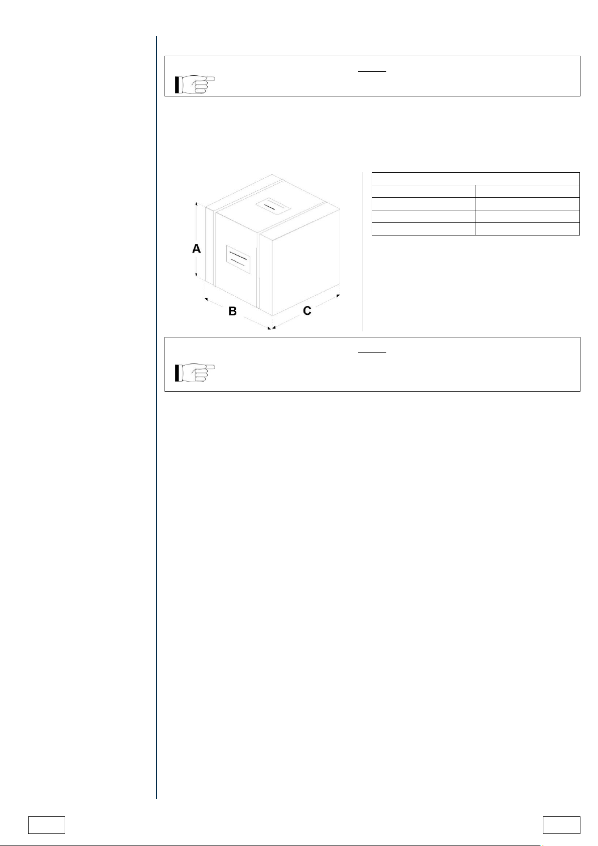
DIMENSION AND WEIGHT ..............................................................................................7
DESCRIPTION OF THE CONTENT .................................................................................7
PRODUCT HANDLING .....................................................................................................8
EMPTYING OF DETERGENT RESERVOIR AND WATER CIRCUIT..............................8
PRODUCT PRESENTATION ................................................................................................9
GENERAL CHARACTERISTICS ......................................................................................9
LCD ICONS .....................................................................................................................11
EXAMPLE OF WORKING CYCLE ..................................................................................11
SETTING UP THE DEVICE.................................................................................................12
FOREWORD ...................................................................................................................12
FOOT ADJUSTMENT......................................................................................................13
GENERAL PRECAUTIONS FOR INSTALLATION .........................................................13
ELECTRICAL CONNECTIONS.......................................................................................14
HYDRAULIC SET-UP......................................................................................................15
WATER FILLING .......................................................................................................15
HYDRAULIC SYSTEM REQUIREMENTS................................................................15
MAINS WATER .........................................................................................................16
WATER DRAINAGE..................................................................................................16
FIRST START-UP ...............................................................................................................18
DOOR OPENING ............................................................................................................18
BASKET EXTRACTION AND INSERTION .....................................................................19
FILLING OF SALT RESERVOIR.....................................................................................20
FILLING OF DETERGENT RESERVOIR........................................................................21
VALIDATED DETERGENTS ...........................................................................................21
DOOR CLOSING.............................................................................................................22
STARTING.......................................................................................................................23
MAIN MENU ....................................................................................................................23
CONFIGURATION...............................................................................................................24
SETTINGS.......................................................................................................................24
PREPARATION OF THE MATERIAL..............................................................................38
CYCLES...............................................................................................................................40
THERMAL DISINFECTION CYCLE (D90) ......................................................................40
WASHING CYCLE (W)....................................................................................................42
PRE-WASHING CYCLE ..................................................................................................43
CUSTOM CYCLES..............................................................................................................45
THERMAL DISINFECTION CYCLES SET BY THE USER (D1 CUSTOM, D2 CUSTOM)45
WASHING CYCLE DEFINED BY THE USER (W1 CUSTOM) .......................................47
DRYING FUNCTION ...........................................................................................................49

EN
OPERATOR'S MANUAL
3
DELAYED START FUNCTION ........................................................................................... 50
EXECUTION OF THE CYCLE ........................................................................................ 51
CYCLE OUTCOME .........................................................................................................51
DOOR OPENING AT THE END OF THE CYCLE ..........................................................52
MANUAL INTERRUPTION..............................................................................................52
DATA MANAGEMENT ........................................................................................................53
APPENDIX - TECHNICAL CHARACTERISTICS................................................................60
SUMMARY TABLE..........................................................................................................60
SAFETY DEVICES .......................................................................................................... 61
SUMMARY TABLE OF CYCLES ....................................................................................62
PROGRAMMES SCHEME..............................................................................................64
APPENDIX - MAINTENANCE ............................................................................................. 65
FOREWORD ...................................................................................................................65
ORDINARY MAINTENANCE PROGRAMME .................................................................65
SCHEDULED MAINTENANCE MESSAGES............................................................ 66
DESCRIPTION OF MAINTENANCE INTERVENTIONS ................................................67
CLEAN THE GASKET...............................................................................................67
CLEAN EXTERNAL SURFACES..............................................................................67
CLEAN WASHING CHAMBER .................................................................................67
CLEAN CHAMBER FILTERS....................................................................................68
HEPA FILTER REPLACEMENT ............................................................................... 69
CLEAN THE ROTARY NOZZLE ............................................................................... 69
PERIODIC THERMO-DISINFECTOR VALIDATION ...................................................... 70
DEVICE USEFUL LIFE ................................................................................................... 71
DISPOSING THE EQUIPMENT WHEN NO LONGER USED ........................................ 71
APPENDIX - GENERAL PROBLEMS ................................................................................. 72
FOREWORD ...................................................................................................................72
TROUBLESHOOTING .................................................................................................... 73
APPENDIX –ALARMS ........................................................................................................74
FOREWORD ...................................................................................................................74
ALARM INTERVENTION ................................................................................................ 74
SYSTEM RESET.............................................................................................................75
TROUBLESHOOTING .................................................................................................... 76
APPENDIX - ADMIN USER PIN RESET.............................................................................86
APPENDIX - TECHNICAL SERVICE ..................................................................................86

4
OPERATOR'S MANUAL
EN
FOREWORD
Dear Customer
Thank you for choosing this product. We hope that you will find it completely satisfactory.
This manual describes all procedures for the correct use of the device and instructions for
deriving the full benefit from its features. In any case, we will be available to provide
explanations and to receive any suggestions you may have for improving our products or
services.
SYMBOLS USED
NOTE
PAY PARTICULAR ATTENTION TO THE PARAGRAPHS MARKED WITH
THE SYMBOL SHOWN.
WARNING
POTENTIAL DANGER TO PROPERTY. FOLLOW THE INSTRUCTIONS IN
THE MANUAL TO PREVENT POTENTIAL DAMAGE TO MATERIALS,
EQUIPMENT AND/OR OTHER PROPERTY.
HAZARD
THIS SYMBOL INDICATES A POTENTIAL DANGER TO PERSONS.
FOLLOW THE PROCEDURES DESCRIBED IN THE MANUAL IN ORDER
TO AVOID INJURING THE USER AND/OR OTHERS.
HAZARD
THIS SYMBOL INDICATES A POTENTIAL DANGER DUE TO HIGH
TEMPERATURE.
THE MATERIALS THE DEVICE IS COMPOSED OF MUST BE DISPOSED
OF ACCORDING TO THE DIRECTIVE 2012/19/EU.
SYMBOLS ON THE
EQUIPMENT
Potential hazard due to high temperature.
Equipment in accordance with applicable directives.
Symbol for disposal in accordance with Directive 2012/19/EU.
Consult the user manual.
RELEVANT EUROPEAN
DIRECTIVES
The product described in this manual is manufactured in accordance with the highest safety
standards and doesn't represent any danger for the operator if used according to the
following instructions. The product is in accordance with the following European Directives as
applicable:
93/42/CEE,
and subsequent amendments and additions, concerning medical devices.
2011/65/UE,
(Rohs II) on restriction of hazardous substances in electrical and
electronic equipment.

EN
OPERATOR'S MANUAL
5
TECHNICAL
STANDARDS
The device complies with Standards ISO 15883-1 and ISO 15883-2 on Washers/Disinfectors
and with Electric Safety Standards IEC 61010-1 and IEC 61010-2-040.
INTENDED USE
DEVICE FOR PROFESSIONAL USE ONLY NOT INTENDED FOR RETAIL SALE.
The product is intended only for the washing and/or thermal disinfection of re-usable surgical
instruments able to resist to a temperature of at least 80°C.
It is not intended for the washing and thermal disinfection of thermolabile medical devices.
It is not intended for the washing of instruments having deep cavities with reduced opening
(since cleaning and disinfection of the inner parts of cavities are not ensured).
It is not intended for the washing of rotary or electronic instruments, unless they are explicitly
indicated as suitable for ultrasonic washing and thermal disinfection by the manufacturer.
It is not intended for the washing of instruments made of not protected aluminium or with
decorative anodizing.
WARNING
THE DEVICE CAN BE USED BY SKILLED PERSONNEL ONLY. UNDER
NO CIRCUMSTANCES IT CAN BE USED OR HANDLED BY UNSKILLED
AND/OR UNAUTHORISED PERSONS.
WARNING
THE APPARATUS IS NOT A MOBILE OR PORTABLE DEVICE.
WARNING
THE TREATMENT IN THE INSTRUMENT WASHER CAN NEVER
REPLACE STERILIZATION. DISINFECTION IN THE INSTRUMENT
WASHER AIMS AT REDUCING THE RISK OF INFECTION OF
PERSONNEL HANDLING THE INSTRUMENTS DURING
RECONDITIONING PROCESS.
NOTE
INFORMATION CONTAINED IN THIS MANUAL IS SUBJECT TO CHANGE
WITHOUT NOTICE.
THE MANUFACTURER IS NOT RESPONSIBLE FOR DIRECT, INDIRECT
OR ACCIDENTAL DAMAGE RESULTING FROM OR RELATING TO THE
PROVISION OR USE OF THIS INFORMATION.
THIS DOCUMENT MAY NOT BE REPRODUCED, ADAPTED OR
TRANSLATED, IN PART OR IN FULL, WITHOUT THE PRIOR WRITTEN
PERMISSION OF THE MANUFACTURER.
PURPOSE OF THE
MANUAL
The purpose of this manual is to provide instructions for:
- becoming generally familiar with the product;
- its correct installation and configuration;
- its safe, efficient use;
- handling materials before and after washing and/or disinfection.
Its appendixes also provide:
- the product's general technical specifications;
- washing and/or disinfection programme specifications;
- maintenance operations;
- Troubleshooting.

6
OPERATOR'S MANUAL
EN
GENERAL WARNINGS
When using this product, always follow the instructions in the manual and never use it for
anything other than its intended purpose.
WARNING
USER IS RESPONSIBLE FOR THE CORRECT AND REGULAR
INSTALLATION, USE AND MAINTENANCE OF THE DEVICE. IN CASE OF
WRONG INSTALLATION OR USE OR IN CASE OF FAILED OR WRONG
MAINTENANCE, THE MANUFACTURER WILL NOT BE RESPONSIBLE
FOR ANY MALFUNCTION, FAILURE OR BREAKAGE, PROPERTY
DAMAGE OR INJURIES.
Please observe the following precautions in order to avoid injury or property damage:
WARNING
THE USE OF WATER OF INADEQUATE QUALITY CAN SEVERELY
DAMAGE THE DEVICE.
SEE TECHNICAL CHARACTERISTICS APPENDIX IN THIS REGARD.
- Do not pour water or other fluids on the device;
- Do not pour flammable substances on the device;
- Do not use the device in the presence of gases or explosive or inflammable vapours;
- Before performing any maintenance or cleaning intervention ALWAYS DISCONNECT
power supply.
- Make sure the electrical system is grounded according to current laws and/or standards;
- Do not remove any label or nameplate from the device; request new ones, if necessary;
- Use only original spare parts.
WARNING
FAILURE TO COMPLY WITH THE ABOVE RELEASES THE
MANUFACTURER FROM ALL LIABILITY.

EN
OPERATOR'S MANUAL
7
PACKAGE CONTENT
NOTE
CHECK THE INTEGRITY OF THE PACKAGE UPON RECEIPT.
DIMENSION AND
WEIGHT
Once the package is opened, check that:
- the supply matches the specifications of the order (see the delivery note);
- there is no visible damage to the product;
Dimensions and weight
A. Height
600 mm
B. Width
600 mm
C. Depth
700 mm
Total weight
47 kg
NOTE
IN CASE OF WRONG DELIVERY, MISSING PARTS OR ANY TYPE OF
DAMAGE, INFORM IMMEDIATELY AND IN DETAIL THE RESELLER AND
THE CARRIER THAT MADE THE DELIVERY.
DESCRIPTION OF THE
CONTENT
In addition to the thermo-disinfector, the package contains:
1. Operating documentation (with CD-ROM)
2. Detergent package
3. Drainage pipe
4. Detergent filling funnel
5. Detergent reservoir filling container
6. Salt filling funnel
7. Allen wrench for HEPA filter replacement
8. Allen wrench for rotary nozzle maintenance
9. HEPA filter certificate of conformity
10. Basket for cutters
11. Baskets
12. instrument support kit
13. No.2 ties for drain pipe

8
OPERATOR'S MANUAL
EN
PRODUCT HANDLING
Thermo-disinfector removal from package and lifting operations must be carried out by two
persons. Handle the device with a truck or suitable means.
WARNING
WE RECOMMEND TO TRANSPORT AND STORE THE DEVICE AT A
TEMPERATURE NOT BELOW 5°C. EXTENDED EXPOSURE TO LOW
TEMPERATURES MAY DAMAGE THE PRODUCT.
NOTE
KEEP THE ORIGINAL PACKAGE AND USE IT WHENEVER THE DEVICE
IS TO BE TRANSPORTED. THE USE OF A DIFFERENT PACKAGE MIGHT
DAMAGE THE PRODUCT DURING SHIPMENT.
EMPTYING OF
DETERGENT
RESERVOIR AND
WATER CIRCUIT
Before any transport following the first installation, it is necessary to empty the detergent
reservoir.
WARNING
FOR FURTHER INFORMATION ABOUT RESERVOIR EMPTYING
PROCEDURE, PLEASE CONTACT THE TECHNICAL SERVICE
DEPARTMENT (SEE APPENDIX).
If salt is present inside resin regeneration reservoir, some salt solution could leak out of
thermo-disinfector water filling pipe.
Water evaporation could result in the creation of salt crystals around water filling union. To
eliminate salt deposits, rinse with water and dry.

EN
OPERATOR'S MANUAL
9
PRODUCT
PRESENTATION
Tethys H10 thermo-disinfector is the revolutionary proposal in the field of thermal disinfection,
as well as the new point of reference in terms of safety, performance, efficiency and ease of
use.
It is a sophisticated but, at the same time, easy to use device that, thanks to its wide range of
configuration options, meets any need of washing and disinfection of medical equipment,
ensuring the maximum performance in any conditions.
Thanks to its extreme ease of use, small size and pleasant appearance, it is the ideal partner
for all professionals who require maximum functionality and safety of the washing and
thermal-disinfection process.
GENERAL
CHARACTERISTICS
Tethys H10 thermo-disinfector is an electronic thermo-disinfector, entirely operated by a
micro-processor.
The exclusive disinfection system, the effective hydraulic circuit and the electronic
management (integrated by high-precision sensors) ensure a high execution speed of the
process and an excellent stability of thermodynamic parameters.
Moreover, its Process Evaluation System constantly monitors all the machine's “vital”
parameters in real-time, guaranteeing absolute safety and a perfect result.
It offers users 6 programmes, some of which provided with customizable, optimized drying for
the fast, effective disinfection of the various types of loads (instruments and materials) used
in a medical environment.
All the cycles can immediately be selected on the clear LCD screen, which also allows
extensive configuration of the device according to the user’s needs.
For further details please refer to 'Configuration' chapter.
The new Tethys H10 thermo-disinfector has the most complete, sophisticated and advanced
safety systems available today, to ensure the user against any electrical, mechanical, thermal
or functional fault.
NOTE
FOR THE DESCRIPTION OF SAFETY DEVICES, REFER TO TECHNICAL
CHARACTERISTICS APPENDIX.

10
OPERATOR'S MANUAL
EN
1. Door
2. Control panel and LCD
screen
3. Power switch
1. Door locking system
2. Air inlet
3. Rotary nozzle
4. Detergent inlet
5. Decalcified water inlet
6. HEPA filter
7. Temperature probe input
(process validation)
1. Stainless steel chamber
2. Stainless steel basket
3. Detergent reservoir
4. Salt reservoir
5. Chamber drainage filter
1. Air / vapour outlet
2. Cooling fan
3. Hose for connection to the
mains water with
"Aquastop" system
4. Foot
5. Water drainage connection
6. Ethernet connection
7. Network fuses
8. Power cable
9. Connection to external
filling accessories

EN
OPERATOR'S MANUAL
11
LCD ICONS
1. SETTINGS
2. TIME AND DATE
3. LAST CYCLE PERFORMED
4. DATA MANAGEMENT
5. WASHING AND DISINFECTION CYCLES
6. LAST STARTED CYCLE OF THE
"OTHER CYCLES" MENU
Management of thermo-disinfector settings
Management of data and information
Menu of washing and disinfection cycles
NOTE
OTHER PARTICULAR SYMBOLS RELATING TO THE VARIOUS CONDITIONS
OF USE WILL BE DESCRIBED IN THE RELATIVE PARAGRAPHS.
EXAMPLE OF
WORKING CYCLE
The disinfection programme of Tethys H10 series can be effectively described as a
succession of phases, each one with a very precise purpose.
Example of washing cycle with ultrasounds and disinfection:
WASHING TIME means the period of time between the reaching of set washing temperature
and drainage start.
NOTE
PLEASE REFER TO PROGRAMMES APPENDIX FOR MORE DETAILS ON
PROGRAMMES.
WARNING
AT THE END OF THE CYCLE IT IS ESSENTIAL TO VISUALLY INSPECT
THE OBJECTS TO CHECK THEIR PROPER WASHING.

12
OPERATOR'S MANUAL
EN
SETTING UP THE
DEVICE
FOREWORD
The first and essential step for a proper and safe operation of the thermo-disinfector, its
durability and complete use of its features is a correct installation, through the thorough
compliance with these instructions.
NOTE
TECHNICAL SERVICE DEPARTMENT (SEE APPENDIX) IS AVAILABLE
FOR ANY DOUBT OR FURTHER INFORMATION.
Installation dimensions
Height (with door open)
835 mm
Width
600 mm
Installation depth
560 mm
Total weight under work conditions
50 kg

EN
OPERATOR'S MANUAL
13
FOOT ADJUSTMENT
Thermo-disinfector Tethys H10 features four adjustable feet allowing to perfectly level it and
compensate for any imperfection of the bearing surface. Feet can be adjusted by simply
screwing or loosening them.
POWER SUPPLY
The electrical system to which the thermo-disinfector will be connected must be suitably
dimensioned according to the electrical characteristics of the device. This information is
shown on the back of the machine.
GENERAL
PRECAUTIONS FOR
INSTALLATION
To ensure a correct operation of the device and/or avoid risk situations, respect the following
warnings:
- Install the thermo-disinfector on a flat and perfectly horizontal surface, work on the
adjustable feet, if necessary.
- Check that the bearing surface is strong enough to support the weight of the device in
operating conditions (about 50 kg);
- Leave adequate room for ventilation all around the thermo-disinfector, in particular in the
rear area.
- Do not install the thermo-disinfector too close to chambers, sinks or similar places,
avoiding contact with water or liquids. This could cause short circuits and/or potentially
dangerous situations for the operator;
- Do not install the thermo-disinfector in excessively humid or poorly ventilated
environments;
- Do not install the machine in environments with flammable and/or explosive gases or
vapours;
- Install the device so that the supply cable is not bent or squeezed.
It must freely run all the way to the electrical outlet.
- Install the device so that the filling/drainage pipes are not bent or squeezed. Place the
pipes so as to avoid drainage water backflow.

14
OPERATOR'S MANUAL
EN
ELECTRICAL
CONNECTIONS
The thermo-disinfector must be connected to a socket of the electric system having adequate
capacity for the absorption of the device and properly earthed, in accordance with laws
and/or regulations in force.
The socket must be properly protected through magneto-thermal and differential circuit
breakers having the following characteristics:
Rated current In
230-240V/50Hz
10 A
220V/60Hz
10 A
120V/60Hz
15 A
Residual current IDn
230-240V/50Hz
0.03 A
220V/60Hz
120V/60Hz
WARNING
THE MANUFACTURER IS NOT RESPONSIBLE FOR DAMAGES CAUSED
BY THE INSTALLATION OF THE THERMO-DISINFECTOR WITH
UNSUITED ELECTRIC SYSTEMS AND/OR NOT PROPERLY EARTHED.
NOTE
ALWAYS CONNECT THE POWER CORD DIRECTLY TO THE POWER
OUTLET.
DO NOT USE EXTENSIONS, ADAPTERS OR OTHER ACCESSORIES.
WARNING
IT IS ESSENTIAL THAT THE ELECTRIC SYSTEM TO WHICH THE
MACHINE IS CONNECTED COMPLIES WITH THE REGULATION IN
FORCE.
WARNING
ANY ELECTRIC CHECKS AND PREPARATION OF SYSTEMS MUST BE
WORKMANLIKE PERFORMED BY SKILLED PERSONNEL, HAVING
PROVEN EXPERTISE AND AUTHORIZED TO OPERATE ON ELECTRIC
SYSTEMS.
COMPETENT STAFF SHALL CHECK THAT EARTH CONNECTION IS
EFFICIENT.

EN
OPERATOR'S MANUAL
15
HYDRAULIC SET-UP
WATER FILLING
WATER INLET CONNECTION
The device is equipped with mains water filling pipe.
Pipe is pre-set for tap connection, with integrated "Aquastop" system serving as a protection
against any water leak, with 3/4" gas threaded connector.
NOTE
TO AVOID BACK-SIPHONAGE TO THE WATER MAINS, INSTALL A NON-
RETURN DEVICE ACCORDING TO PREVAILING STANDARDS.
NOTE
IF FILLING PIPE MUST CROSS A TOP, ARRANGE A D=75 mm HOLE.
MINIMUM HOLE D=65 mm REQUIRES THE REMOVAL OF AQUASTOP
SOLENOID VALVE SHELL (A).
POSITIONING OF FILLING TAPS
Filling taps must be positioned near the device, in a position accessible to the user.
For the positioning of filling taps there are no special constraints of height, except the length
of the supplied pipes, approx. 2 metres.
NOTE
TO PREVENT THE RISK OF CLOGGING OR DAMAGE, IF WATER
PIPELINE IS NEW OR HAS BEEN INACTIVE FOR A LONG PERIOD OF
TIME, MAKE SURE THAT WATER IS CLEAR AND WITHOUT
CONTAMINATION BEFORE CARRYING OUT WATER CONNECTION
HYDRAULIC SYSTEM
REQUIREMENTS
Check that the water supply pressure is within the required limits:
-minimum pressure 2 bar
-maximum pressure 5 bar.
NOTE
TO AVOID ANY FLOODINGS DUE TO POSSIBLE FAILURES, WE
RECOMMEND TO CLOSE THE MAINS WATER TAP WHEN THE DEVICE
IS NOT OPERATING, IN PARTICULAR AT NIGHT.

16
OPERATOR'S MANUAL
EN
MAINS WATER
For the operation of the machine it is necessary a connection to a 'drinkable' water mains
providing water with maximum hardness of 54°f, and total dissolved iron content, Fe2+ and
Fe3+, not exceeding 0.5 ppm.
NOTE
IF MAINS WATER CONTAINS A QUANTITY OF FE2+/FE3+ IRON
EXCEEDING 0.5 PPM AND/OR MAINS WATER HARDNESS EXCEEDS
54°f (FRENCH DEGREES), A PRE-TREATMENT OF WATER MUST BE
CARRIED OUT BY INSTALLING A DEFERRIZATION AND/OR SOFTENING
SYSTEM UPWARDS.
NOTE
IF A SOFTENING SYSTEM IS ALREADY AVAILABLE ON SITE,
CONNECTED TO MAINS WATER AND ABLE TO SUPPLY WATER WITH
MAXIMUM HARDNESS OF 10°f, MEASURE THE VALUE IN FRENCH
DEGREES (°f) OF MAINS WATER HARDNESS AND SET THE
CORRESPONDING HARDNESS VALUE IN THE RELEVANT MENU.
THERMO-DISINFECTOR DISABLES RESIN AUTOMATIC
REGENERATION IF WATER HARDNESS SET VALUE IS LOWER THAN
10°f.
SEE INSTRUCTIONS IN "WATER HARDNESS" SECTION
WATER DRAINAGE
Drain pipe of the device:
rubber end for hose fitting diameter 19-22 mm (1/2").
WATER DRAINAGE CONNECTION
The device is equipped with a drain pipe.
WARNING
ARRANGE DRAIN PIPE SO AS TO AVOID DEPRESSIONS AND SHARP
BENDS TO PREVENT THE TRAP EFFECT AS WELL AS OPERATING
FAILURES.
WARNING
DRAINAGE MUST BE MADE IN COMPLIANCE WITH THE
INTERNATIONAL AND NATIONAL STANDARDS AND UNDER THE
EXCLUSIVE RESPONSIBILITY OF THE USER.

EN
OPERATOR'S MANUAL
17
WARNING
IT IS ADVISABLE TO CONNECT THE DRAINAGE PIPE TO A SIPHON
WITH A MINIMUM HEIGHT OF 50 MM THAT CAN BE INSPECTED FROM
THE LOWER PART.
During installation operations please observe the following precautions:
- since the temperature of drainage water is 95°C, both drainage pipe ends must be fixed
to the hose fitting and duly secured in place with the supplied clamp;
- the end of the drainage pipe must be placed at a height that complies with specifications,
with respect to the support surface of the device;
- the inner diameter of the fixed drainage pipe shall be at least 40 mm;
- prolongations of the supplied drainage pipe shall not be carried out. Possible
prolongations may cause drainage problems.

18
OPERATOR'S MANUAL
EN
FIRST START-UP
To open the thermo-disinfector it is necessary to release the door applying moderate force
and take it to the vertical position.
DOOR OPENING
WARNING
TO PREVENT THE RISK OF FINGER CRUSHING TAKE THE DOOR TO
ITS COMPLETE OPENING.

EN
OPERATOR'S MANUAL
19
BASKET EXTRACTION
AND INSERTION
Remove the basket by seizing it through the proper handles as shown in the figure.
Once it is refitted inside the chamber, make sure that both handles are correctly positioned in
the proper seats on the chamber surface.
NOTE
HANDLE WRONG POSITIONING MAY LEAD TO WATER LEAKAGE
DURING CYCLES AND THE DEVICE COULD SHOW OPERATING
MALFUNCTIONS.

20
OPERATOR'S MANUAL
EN
FILLING OF SALT
RESERVOIR
The thermo-disinfector is equipped with an inner salt reservoir, used for regeneration of ion
exchange resins contained in the integrated water softening system.
At the first use after installation it is necessary to fill completely the reservoir with water, then
with salt.
Unscrew the salt reservoir plug, insert the supplied funnel, fill reservoir with water, and slowly
pour the salt up to the appearance of the salt at the plug level. Check that the maximum
reservoir filling level is not exceeded. At the end of the operation screw the plug in its seat
and wait for about 5 minutes until the salt is dissolved.
WARNING
USE NON-IODIZED COARSE SALT OR SALT FOR DISHWASHERS.
AT THE END OF THE FILLING OPERATION RINSE THE SURFACE WITH
CLEAN WATER AND REMOVE ALL TRACES OF SALT AND WATER
FROM THE SURFACE USING A CLOTH OR ABSORBENT PAPER.
WARNING
POSITION SALT FILLING FUNNEL SO THAT GUTTER IS FACING INSIDE
THE CHAMBER IN ORDER TO PREVENT WATER FROM BEING SPILLED
ON THE SURFACE.
Table of contents
Other Mocom Laboratory Equipment manuals

Mocom
Mocom Exacta User manual

Mocom
Mocom B FUTURA User manual

Mocom
Mocom B28 Series User manual

Mocom
Mocom millennium B User manual

Mocom
Mocom S Classic 17 User manual

Mocom
Mocom B Futura-17 User manual

Mocom
Mocom Tethys D60 User manual

Mocom
Mocom millenium B2 User manual

Mocom
Mocom Autoklav B Futura 28 Liter User manual

Mocom
Mocom SUPREME 17 User manual
Popular Laboratory Equipment manuals by other brands

GYROZEN
GYROZEN 1730R user manual

Slee
Slee Cryostat MEV operating instructions

Healthmark
Healthmark FIS-007HB Instructions for use

Thermo Scientific
Thermo Scientific Labofuge 200 Operating lnstructions

Gamry Instruments
Gamry Instruments PTC1 Operator's manual

Belden
Belden Hirschmann RPI-P1-8PoE instruction manual