feedback 550603 User manual

~
Sine-Square
,
Oscillator
550603
QUARE
OSCILLATOR
OUTPUT
Vpk-pk
,
.....
~
{;/
::-
,,--
=-
POWER
=-...
0",=
:::
~
'l
"
......
~
~.$
--'\r-.ru-~-
I
,;::;
'l
€'
~.::::
TTL
only
SYNC
OUT
//-
9 "
rv
'///1
..
s
\,'
'11111(,
11\\\\\\
•
FEEDBACK
www.g0rsq.co.uk

Sine-Square
Oscillator
550603
Contents
Section
1
Description
Section
2 Operation
Section
3
Circuit
Description
Section
4 Maintenance
E
FEEDBACK
INSTRUMENTS
LIMITED
CROWBOROUGH
SUSSEX
ENGLAND
Telephone:
Crowborough
(08926)
3322
Cables: Feedback
Crowbr
Telex:
95255
Manual
603
EdC
0480
Printed
in
England
by
FI
Ltd,
Crowborough

I
Feedback
Instruments
Lld
Component replacement
Although
this
Feedback
manual
was
believed
to
be
correct
at
the
time
of
printing,
components
supplied
may
differ
slightly
from
those
described.
We
endeavour
continually
to
improve
our
equipment
by
incorporating
the
latest
developments
and
components,
even
up
to
the
time
of
despatch.
Whenever
possible
we
will
include
such
new
or
revised
information.
Whenever
possible,
replacement
components
should
be
similar
to
those
originally
supplied.
These
may
be
ordered
direct
from
Feedback
Instruments
Limited
or
its
agents
by
quoting
the
following
information;
1.
Equipment
type
2.
Equipment
serial
number
3.
Co'mponent
reference
4.
Component
value
Standard
components
can
often
be
replaced
by
alterna·
tives
available
locally.
COPYRIGHT
NOTICE
©
Feedback
Instruments
Limited.
All
rights
reserved.
No
part
of
this
publication
may
be
reproduced,
stored
in a
retrieval
system,
or
transmitted,
in
any
form
or
by
any
means,
electronic,
mechanical,
photocopying,
recording
or
otherwise,
without
the
prior
perm:ssion
of
Feedback
Instruments
Limited
2
The Health
and
Safety at Work Act
1974
We
are
required
under
the
Health
and
Safety
at
Work
Act
1974,
to
make
available
to
users
of
this
equipment
certain
information
regarding
its safe use.
The
equipment,
when
used
in
normal
or
prescribed
applications
withtn
the
parameters
set
for
its
mechanical
and
electrical
performance,
should
not
cause
any
danger
or
hazard
to
health
and
safety
if
normal
engineering
practices
are
observed
and
they
are
used
in
accordance
wi
th
the
ins
tructi
ons
suppl ied.
If, in
specific
cases,
circumstances
exist
in
which
a
potential
hazard
may
be
brought
about
by
careless
or
improper
use,
these
will be
pointed
out
and
the
necessary
precautions
emphasized.
While
we
attempt
to
give
the
fullest
possible
user
information
in
our
handbooks,
if
there
is
any
doubt
whatsoever
about
any
aspect
relating
to
the
proper
use
of
this
equipment
the
user
should
contact
the
Product
Safety
Officer
at
Feedback
Instruments
Limited,
Crowborough.
DESCRIPTION
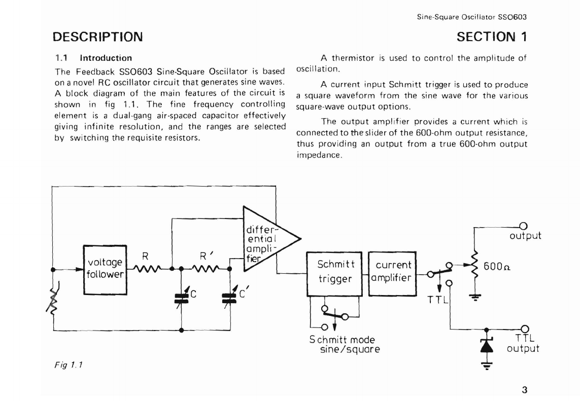
1.1 Introduction
The
Feedback
SS0603
Sine-Square
Oscillator
is
based
on
a novel RC
oscillator
circuit
that
generates
sine waves.
A
block
diagram
of
the
main
features
of
the
circuit
is
shown
in fig
1.1.
The
fine
frequency
controlling
element
is
a
dual-gang
air-spaced
capacitor
effectively
giving
infinite
resolution,
and
the
ranges
are
selected
by
switching
the
requisite
resistors.
Sine-Square
Oscillator
SS0603
SECTION 1
A
thermistor
is
used
to
control
the
amplitude
of
oscillation.
A
current
input
Schmitt
trigger
is
used
to
produce
a
square
waveform
from
the
sine
wave
for
the
various
square-wave
output
options.
The
output
amplifier
provides
a
current
which
is
connected
to
the-slider
of
the
600-ohm
output
resistance,
thus
providing
an
output
from
a
true
GOO-ohm
output
impedance.
I
C
I R I
AI\.~I\./'-....a
output
•
...
voltage
lA
R Schmit t
current
600n
follower amplifier
trigger
S
chmitt
mode
sine/square
Fig
1.1
~
3

Feedback
Instruments
Ud
When
the
TTL
output
is
selected
the
output
1.2
Mechanical
current
is
shunted
by
a zen
er
diode
to
keep
the
output
The
550603
is
housed
in
an
ASS
plastic
case
made
in
voltage
and
output
impedance
at
values
suitable
for
two
halves
each
secured
by
two
screws
on
each
side.
TTL.
The
case
provides
the
main
structural
strength
of
the
A
separate
sinewave
'sync'
output
is
continuously
instrument.
Removal
of
the
case
gives access
to
all
available
for
oscilloscope
synchronisation
or
frequency
components.
Without
the
cover
the
SS0603
consists
of
monitoring
. a
horizontal
PWB
fixed
by
small
plastic
brackets
to
the
•
FEEDBACK
SINE
FAEQUEN~
IOk-IOk
100-1
Ok
IDk-IOOk
,,'\
I !
OUTPUT
IQ-lOO
..
Vpk-pk
IOQk-l
o~~
.
.'"
Hz
6
:.'~
-
POWER
o "
=--
...
0:=
/
~
$'
",
~
,\;ru
'"L
•
""-/
'"
~
T f l
()f'ly
'>'
(
UUI
'\;
//;1/
" .. fi
~
\ '
1/1/111/11 \ \
Ill'
I
IIII
Fig 1.2
4

front
and rear panels.
This
provides a
structure
strong
enough
for
normal
handling
and maintenance.
The
low
power
dissipation
of
the
SS0603
obviates
the need
for
ventilation
holes. The
oscillator
tuning
capacitor
and associated resistors are
mounted
in a die-
cast metal screening
box
fixed
to
the
front
panel. This
provides
complete
electrostatic
screening and
protection
from
dust
for
the sensitive high-impedance
circuit.
All
controls
are situated on the
front
panel shown
in fig 1.2.
They
are:
Power Red push
button
power
switch
Separate red
power
indicator
Frequency
Rotary
range
switch
0..
r-.
Fine
frequency
control
(approx·
Q
imately
logarithmic
cal
ibrated
"
frequency
dial)
Waveform
Selection
Four
black push
buttons
Amplitude
Single
rotary
control
Output
terminals Main
output
from
pair
of
Red
and Black
4mm
socket
binding
posts
TTL
Output
Separate
4mm
socket
Sync
out
4mm
socket
Sine-Square Oscillator
SS0603
1.3 Specification
of
type
SS0603
The
SS0603
is
a general-purpose, solid state
'RC'
sine
oscillator
providing
sine wave
or
square wave
outputs.
Frequency
Range
10Hz
to
1MHz
in five switched ranges.
Resolution
-
infinite.
Range Overlap
25% at
top
of
each range and 10% at
bottom
of
each
range.
Scale
Accuracy
±5%
of
setting.
Typically
±2%
of
setting.
Frequency
Stability
Measured at 1
kHz
on 1
to
10kHz
range.
Drift
Typically
50ppm
per
10
minutes
measured
after
10
minutes
warm
up.
Supply
voltage change
Typically
0.003%
for
10% change
in
supply
voltage.
Main
Output
Waveforms
Sine, Square
or
Positive-only
Square wave selected
by
pushbuttons.
Output
Impedance
nominally
600
ohms.
5
Feedback
Instruments
L
td
Amplitude
Control
Single
continuous
control
nominally
0-15V
pk-
pk
at
1V
pk-pk
intervals.
Minimum
Usable
Output
Typically
200mV
pk-pk.
Amplitude
Stability
Typically
±1% over frequency range.
Offset
The
d.c
component
on the sine and square waveforms
is
separately set
by
internal adjustments and
is
normally
set
to
within
0.1V
of
zero. This d.c
component'
is
reduced
proportionally
to
the signal
output
by
the
output
control
(or
by
resistive loading).
Terminations
4mm
binding
posts (Hi-red and Lo-black) on J;';"
pitch
Purity
Sine
distortion
less
than
05%
at 1kHz.
Square wave rise and fall times -
less
than 100ns.
Auxiliary Outputs
TTL compatible square wave Available
only
when
appropriate
pushbutton
is
depressed.
Amplitude
+3.5
to
+4.5V
in the 'high' state and
o
to
·lV
in the
'Iow'
state.
Rise Time
Less
than 100ns.
6
Current sink capacity Eight standard
TT
L loads.
Termination
4mm
socket
Sync
Out
Continuously
available sine
waveform
Amplitude
2
to
6V
pk-pk
DC
component
Less
than
4V
d.c
Impedance 1k
r2
Termination
4mm
socket
Power requirements
Line
voltage
200!250V
or
1
00!125V
rms,
50
or
60Hz.
Consumption
5VA
Fuse
315mA
slow
blow
(20mm
x
5mm)
Littel
fuse
style
213
Seswick
TDC
123
Suss
GMA
Dimensions and Weight
Width
300mm
(1
2in)
Height
(with
feet)
115mm
(45in)
Depth
225mm
(gin)
Weight
2.1
kg
(4.63Ib)
OPERATION
2.1 I
nstallation
of
SS0603
The
oscillator
·is
packed
in inserts
of
expanded
poly-
styrene
to
prevent
damage
in
transit.
On
opening
the
end
of
the
corrugated
cardboard
container,
the
inserts
together
with
the
SS0603
should
be
smoothly
withdrawn
from
the
container.
Take
care
that
the
inserts
and
the
SS0603
are
held
together
during
this
time.
I
nspect
the
SS0603
and
if
any
damage
is
evident
immediately
notify
the
carrier.
2.2
Voltage
Selection
Ensure
that
the
instrument
is
set
to
the
appropriate
voltage
supply.
This
is
effected
either
by
inspecting
the
tag (if
fitted)
on
the
power
cable
or
by
checking
the
voltage
selection
switch
after
removing
the
top
cover
of
the
instrument.
Voltage
selection
is
accomplished
by
a slide
switch
on
the
printed
circuit
board;
it
has
positions
marked
'115'
and
'230'.
Set
the
switch
to
'115'
for
operation
from
100
to
125
volts
and
to
'230'
for
200
to
250
volts.
Wire
connections.
The
colour
code
of
the
power
supply
cable
is:
Brown
Live
Blue
Neutral
Green/Yellow
Ground
Sine-Square
Oscillator
SS0603
SECTION 2
The
ground
wire
is
connected
to
the
front
and
rear
panels
of
the
SS0603
and
to
the
common
terminal
on
the
front
panel.
2.3
Frequency
Selection
Any
value
of
frequency
in
the
range
10Hz
to
1MHz
may
by
obtained
by
use
of
the
range
switch
and
fine
frequency
control.
The
rotary
range
switch
provides
the
following
frequency
decades:
10Hz
to
100Hz
100Hz
to
1.0kHz
1.0kHz
to
10kHz
10kHz
to
100kHz
100kHz
to
1MHz
The
required
frequency
is
set
by
the
variable
control,
graduated
1
to
10
(0.9
to
13
with
overlap).
For
example,
to
set
3.6kHz
turn
the
range
switch
to
the
1.0kHz
to
1OkH z range
and
turn
the
variable
control
to
3.6.
2.4
Outputs
Selection
A
required
output
waveform
is
selected
by
pushing
one
of
the
four
output
selection
buttons
-
Sine,
Square,
positive
only
square
wave
or
TTL-compatible
square
wave.
Of
these
four
options,
only
the
TTL
output
is
available
from
a
separate
4mm
socket,
the
remainder
being
available
from
the
Main
Output.
7

Feedback
Instruments
Ltd
Main
Output
The
amplitude
of
the
output
waveform
is
set
by
the
output
control
knob
cal i
brated
from
0
to
15V
pk-pk
and
is
the
open-circuit
or
no-load
voltage.
The
output
impedance
is
600
ohms
and
any
loading
will
lower
the
output
voltage.
In
particular
if
loaded
with
600
ohms
the
terminal
voltage
will
be
half
that
indicated.
TTL
Output
This
output
is
available
from
a
separated
4mm
socket
when
the
appropriate
pushbutton
is
depressed.
The
separate
output
is
provided
as a
precaution
against
accidental
damage
that
might
ensue
should
an
overvoltage
be
applied
and
the
wrong
waveform
pushbutton
depressed.
The
output
ampl
itude
is
fixed
and
is
5-volt
TTL-compatible.
The
output
impedance
is
low
when
in
the
'0'
or
'1'
condition
and
is
high
during
transition.
SVnc
Output
This
extra
sinewave
is
continuously
available
and
is
Intended
for
such
functions
as
frequency
monitoring
and/or
oscilloscope
synchronisation.
In
the
latter
case
the
use
of
a
sinewave
allows
a
certain
amount
of
phase
adjustment
of
the
oscilloscope
display
by
adjustment
of
the
oscilloscope
trigger
level.
Phase relationships
The
sync
output
is
in
phase
with
the
main
sine wave
output
and
in
approximate
anti-phase
to
the
various
square
wave
outputs.
8

CIRCUIT DESCRIPTION
For
convenience
the
circuits
in
this
section
are
simplified
or
in
the
form
of
block
diagrams.
The
full
circuit
is
shown
in
fig
4.4.
3.1 RC Frequency Network
The
basic
oscillator
is
based
on
the
circuit
shown
in
fig
3.1.
V1
r;r
Fig
3.1
This
circuit
was
used
in
preference
to
other
RC
circuits
because
it
enables
the
frame
of
the
double-gang
variable
capacitor
C,
C'
to
be
grounded.
At
resonance
the
oscillatory
voltages
will be as in
the
phasor
diagram
fig
3.2.
The
amplifier
A
amplifies
VR'
by
X3,
to
provide
5ine-5Quare
Oscillator
550603
SECTION 3
the
voltage
V I
to
maintain
oscillation.
The
phase
and
gain
relationship
of
the
network
RCR'C'
is
very
similar
to
that
of
the
active
side
of
the
well-known
Wien Bridge.
1
The
resonant
frequency
is
f
'"
---
where
R
'"
R'
27TRC
and
C
'"
C'.
vc'~7
VR/
Fig
3.2
Phasor diagram
The
amplitude
of
oscillation
is
maintained
by
controlling
the
gain
of
the
oscillator
loop
by
means
of
a
thermistor.
3.2
RC
Oscillator Amplifier
Fig
3.3
shows
the
amplifier
used
to
maintain
oscillation
in
the
RC
network.
The
FET's
TR9a
and
TR9b
provide
suitable
high
impedance
inputs
for
connection
from
the
RC
network.
The
differential
input
stage
TR9-11
has
two
outputs.
One
output
is
used
for
feedback
to
the
RC
network
via
the
thermistor
and
the
emitter
follower
TR
14
while
the
other
output
goes
to
the
output'
circuit
which
includes
the
Schmitt
trigger.
The
gain
of
the
9

Feedback
Instruments
Ltd
amplifier
is
principally
determined
by
the
ratio
of
dissipated
in
the
thermistor
causes
its
resistance
to
drop
resistor
network
RA
and
resistor
R2 .
For
steady
so
reducing
the
rate
of
build
up
of
oscillation.
A
point
oscillation
this
ratio
has
to
be
about
1
:3.
When
the
of
equilibrium
is
reached
where
the
thermistor
resistance
thermistor
R2
is
cold
the
ratio
is
much
greater
than
3
and
is
just
three
times
that
of
resistor
network
RA.
so
the
amplitude
of
oscillation
builds
up.
The
power
then
stabilising
the
ampl
itude
of
oscillation.
r-----
I
I
I
sinewave
current
to
output
circuit
differential
in
put
stage
I
TR10
TR11
:
TR9a
TR9b
hi h I
impe~a
n~c~eptl--1~WL.---J
push-pull
I
input
froml
R
.C.
O--+------+--------J
Cire u it I
I
~
RA--~~~
I
L _
Fig
3.3
10

3.3
Schmitt Trigger
Unless
'the
sine
wave
main
'output'
is
selected,
the
Schmitt
Trigger
produces
a
square
waveform
from
the
sinewave
input.
The
circuit
is
shown
in
fig
3.4(a)
and
the
corresponding
waveforms
in
3.4(b).
V
cc
TR18
point B • square
wO
ve
•
out
TR13
point A
sine
current
input
(point
A)
Sine-Square
Oscillator
550603
When
the
sinewave
is
selected
resistor
R42
is
shunted
by
resistor
R34
so
that
switching
does
not
take
place
and
a
sine
voltage
waveform
is
available
at
the
emitter
of
transistor
TR
13.
corresponding
waveforms
Vcc
val tage 8
A
time
1I
\.
Vrefi\1
\
sme
current
input
time
(0 ) (
b)
Fig 3.4a Fig
3.4b
11
Feedback
Instruments
Ltd
3.4
Output
Circuit
The
sine
or
square-wave
voltage
waveforms
generated
by
the
circuit
in fig
3.4(a)
are
converted
to
a
corresponding
current
waveform
by
transistor
TR16.
Transistor
TR19
provides
a
constant-current
load
switched
to
the
appro-
priate
value
for
the
selected
waveform.
When
TTL
is
selected
the
output
current
is
fed
to
a
Zener
diode
to
limit
the
voltage
excursion
abruptly
at
positive
and
negative limits
suitable
for
5-volt
TTL.
For
all
other
output
options
the
output
current
is
connected
to
the
slider
of
the
linear
output
potentiometer
which
is
shunted
to
provide
a
600-ohm
output
impedance.
3.5 Power Supply
The
SS0603
circuit
operates
from
unregulated
positive
a,nd negative
voltage
lines
of
about
25
volts.
The
mains
transformer
has a
double
primary
winding
connected
in series for
200
to
250-volt
operation
and
in
parallel for
100
to
125-volt
suppl
ies.
Voltage
selection
is
effected
conveniently
by
a slide
switch
positioned
on
the
main
PWB.
12

MAINTENANCE
4.1 Fault location
Faults
will
appear
as
abnormal
outputs
from
the
oscillator
or
as
calibration
inaccuracies. The nature
of
the
abnormality
allows the area in
which
the
fault
is
located
to
be
narrowed.
The
oscillator
has
been designed
to
allow
access
to
most
of
the
components
by
removal
of
the
case.
Position
the
carrying
handle
as
in
fig
4.1
thereby
allowing
access
to
the
four
case-fixing screws. Unscrew
with
a Posidrive
No.
2 screwdriver, the
four
screws on each side
of
the
case
and
then
remove
the
handle,
while
pulling
outwards
as
shown
in
fig
4.2
to
avoid scratching the
case.
I
~-
.
~~
U 0
Fig 4.1
5ine-~Quare
Oscillator
550603
SECTION 4
[@]
Fig
4.2
The
top
and
bottom
halves
of
the cover can
then
be
I
ifted
off.
The
chassis
formed
by
the PWB and
front
and rear panels
is
strong
enough
for
normal
handling
during
maintenance.
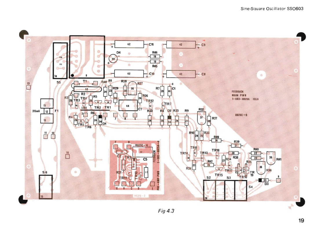
Positions
of
components
and test
points
referred
to
in
the
following
tables can be
found
by
reference
to
the
component
diagram
fig
4.3
and
the
complete
circuit
diagram fig
4.4.
4.2
Preset Controls
Before assuming a
fault
condition,
check
that
the preset
controls
are
not
in need
of
adjustment.
The
following
is
a
list
of
the
controls
and
the
malfunctions
that
can
occur
if
the
controls
are
improperly
set.
13
Feedback
Instruments
Ltd
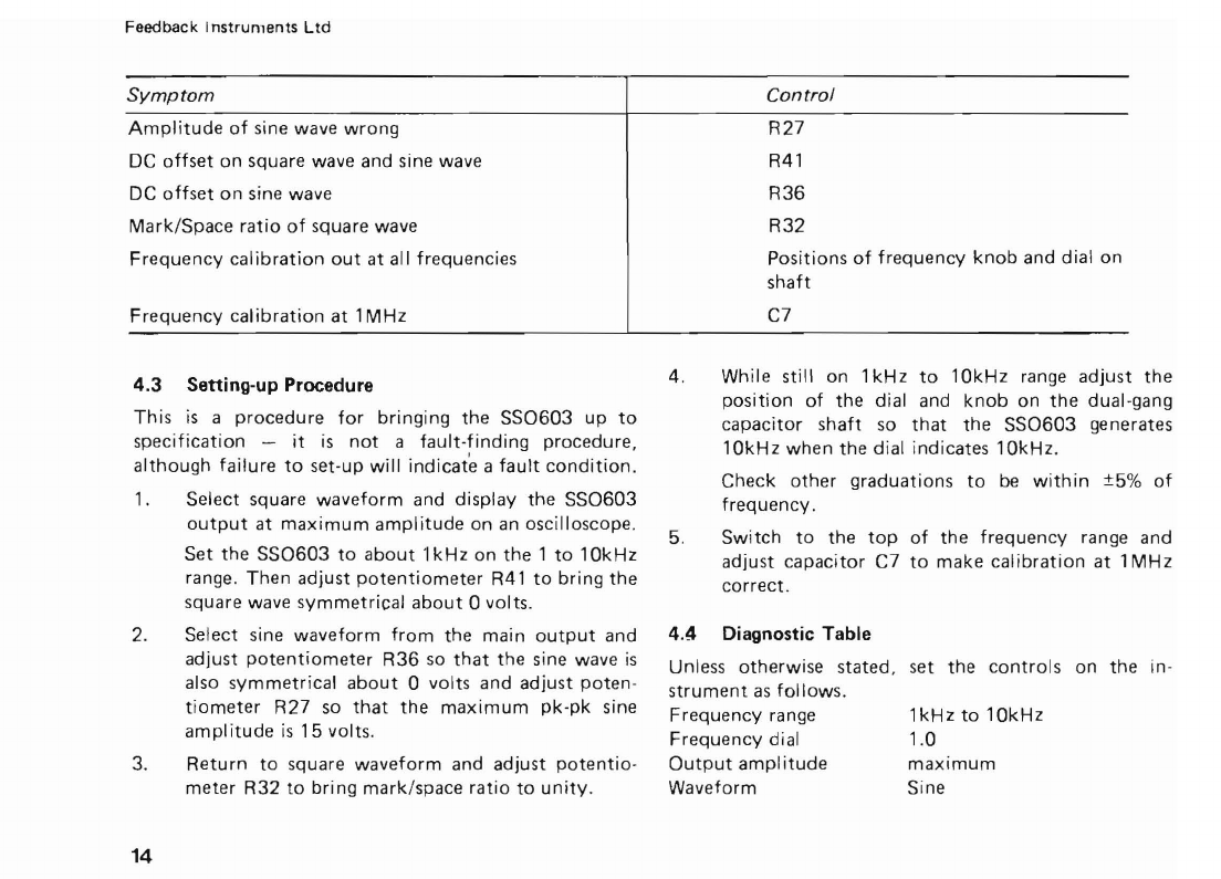
Symptom
Amplitude
of
sine wave
wrong
DC
offset
on
square
wave
and
sine wave
DC
offset
on
sine wave
Mark/Space
ratio
of
square
wave
Frequency
calibration
out
at
all
frequencies
Frequency
calibration
at
1MHz
Control
R27
R41
R36
R32
Positions
of
frequency
knob
and
dial
on
shaft
C7
4.3 Setting-up Procedure
This
is
a
procedure
for
bringing
the
SS0603
up
to
specification
-
it
is
not
a
fault-finding
procedure,
although
failure
to
set-up
will
indicate
a
fault
condition.
1.
Select
square
waveform
and
display
the
SS0603
output
at
maximum
amplitude
on
an oscilloscope.
Set
the
SS0603
to
about
1kHz
on
the
1
to
10kHz
range.
Then
adjust
potentiometer
R41
to
bring
the
square
wave
symmetrical
about
0 volts.
2.
Select
sine
waveform
from
the
main
output
and
adjust
potentiometer
R36
so
that
the
sine wave
is
also
symmetrical
about
0 volts
and
adjust
poten-
tiometer
R27
so
that
the
maximum
pk-pk
sine
amplitude
is
15
volts.
3.
Return
to
square
waveform
and
adjust
potentio-
meter
R32
to
bring
mark/space
ratio
to
unity.
14
4.
While still
on
1kHz
to
10kHz
range
adjust
the
position
of
the
dial and
knob
on
the
dual-gang
capacitor
shaft
so
that
the
SS0603
generates
10kHz
when
the
dial
indicates
10kHz.
Check
other
graduations
to
be
within
±5%
of
frequency.
5.
Switch
to
the
top
of
the
frequency
range
and
adjust
capacitor
C7
to
make
calibration
at
1MHz
correct.
4.4 Diagnostic Table
Unless
otherwise
stated,
set
the
controls
on
the
in-
strument
as follows.
Frequency
range
1kHz
to
10kHz
Frequency
dial
1.0
Output
amplitude
maximum
Waveform
Sine

Sine-Square Oscillator
SS0603
Symptom
Power
indicator
lamp
not
lighting
Failure
to
function
properly
Failure
to
function
Across
D2
8.25V
±0.5V
TR7,
TR12,
TR3, TR5,
properly
TR19,
TR8
Failure
to
function
Across
C1
7.5V
±1V
TR8, TR7,
TR
1
properly
Failure
to
function
properly
Failure
to
function
properly
Failure
to
function
properly
Test
point
Check
power
supply.
Check fuse.
+ve line
-ve line
Across
D1
Across C7
Across R45
(+ve
supply)
current
Across
R46
(-ve
supply)
current
Correct
output
at
Test
Point
Voltage in range
100·125Vor
200-250V
+25
±5V
-25
±5V
8.2V
±0.5V
OV
±0.2V
2.6
±0.3V
(Note
{these
(values
(apply
{only
2.35
±0.3V
(for
(sine
(output
Probable
location
of
fault
Power
supply
Power
supply
or
SiC
on
lines
TR2,
TR14
TR9.
10,
11
(inside
box)
Excessive voltage
implies excess
current
and
short
circuits.
Look
for
burnt
components.
Low
readings
suggest olc
components.
15

Feedback
Instruments
ltd
4.5 Component Replacement Table
The
SS0603
is
not
critical
with
regard
to
component
types
but
proper
performance
can
only
be
expected
if
component
replacements are
of
reasonably
similar
types.
A
brief
general
specification
of
suitable com-
ponents
is
listed together
with
a
look-up
table.
Component
Resistors
Spec
Component
Spec
Component
Spec
Component
Capacitors
Spec
R1
A R16 B R31 A
C1
Q
R2
Thermistor
R17 B R32 E C2 P
R3 A R18 B R33 A C3J M
R4 A
R19
B R34 A
C4
R5 A
R20
B
R35
A C5 L
R6 A
R21
B R36 E C6 P
R7 A R22 B R37 A
C7
L
R8 A R23 A R38 A C8 Q
R9 A R24 A R39 A C9 Q
Rl0
A R25 A R40 A
Cl0
Q
R
11
B R26 A
R41
E
C11
Q
R12 B R27 E R42 A
R13
B
R28
A
R43
H
R14 B R29 A R44 A
R15 B R30 A R45 A
R46 A
16

5ine-5qudre Oscillator
550603
Spec
TVp(!
Rating
Tolerance Fixing Position
A
Resistor
1/8W
or
more
5%
or
less PWB
hole
ctrs
0.6"
Rl,
R3
to
10,
Res. dia. less
than
R28
to
31,
R33
to
~5,
0.2"
R37
to
40,
R42,
R44
to
46.
B
Resistor
1/8W
1%
Mounted
on
Rllto22
frequency
switch
E
Preset
carbon
O.lW
or
more
20%
or
less
See
fig
4.3
R27,
R32,
R36,
R41
or
Cermet
pots
H
Potentiometer
'hW :!:10%
15/16"diam.
R43
wirewound
1"
shaft
lkD
5/8"
FMF
K
Capacitor
100V
±2'h% see fig
4.3
C5
L
Capacitor
100V
PWB
centres
C7
compression
0.6"
0.4"
wide
M
Jackson
Bros.
type
P222
two-gang
510pF
per
section
C3,C4
P
Capacitor
See
fig
4.3
C2,C6
Ceramic
Q
Capacitor
35V
wkg
-20 +
80%
Cl,C8,C9,Cl0,Cll.
Electrolytic
17

I
Feedback
Instruments
Ltd
Transistors
If
the
Ferranti
transistor
types
are
not
available
the
following
types
bearing
EIA
or
Pro-Electron
type
num-
bers
may
be
used.
This
table
does
not
imply
that
the
types
listed
are
equivalents
in
any
other
situation
-~_~_~--,a;_~--=~-C-K-f-----=-;_~A_9-=-3-0--+--
:~~~~~tron
ZTX213CK
2N3251 BC213C
ZTX313CK
2N2369 BSX20
Other
components
are listed
below
with
the
Manu-
factu
rer'
s na
me.
Circuit
ref
Type
No
Manufacturer
=T--=R--=9:-------1--
J
-:-'4'-":-::2:----+--
Si
Iiconix
R2
RA54
STC
Other
components
including
mains
transformer
and
switches
are
supplied
to
Feedback
specifications
and
should
be
ordered
through
Feedback
Instruments
Limited,
Crowborough,
Sussex.
Returned
instruments
Should
the
instrument
be
returned
for
repair
and
recali-
bration
at
any
time,
the
mains
plug
should
be
removed,
as
no
provision
for
the
plug
is
included
in
the
packing
when
we
return
the
instrument
to
you.
The
address
to
which
an
instrument
should
be
returned
is:
Feedback
Instruments
Limited,
Serv
ici
ng
Department,
Park
Road,
Crowborough,
TN6
2QR,
Sussex,
England.
__
I
dr
,,"e
I
,}'
Sine-Square
Oscillator
550603
41
,.
R46
--rr:::r
--rr:::r
"'"
R4S
,
---.z----,b,.c.
lO
"
d"
I
R6'
"
\'
'~,',','_....
T
11
/"
lDT
00
\
"~108~Rf
:49
".,
"
-ITJ-:r
~~
f-
TR8J
TR18
'R40
g
TR1~
~R13';:"
Cl
e-qD-
;-00-
r.:l
1
tJ
«
ffi
~
R34
R38
'-OD-
U
R41
"
Id
'~-i
:42
h
ZI
fl
Jb~~
r:l
'
R24J;J
<
~
"rRf7
liJ.\,-~TR
(JR36
, TIl15
TR~
19
I
~,
'0IIJ\52
-q-
"
53"
[J
"\.
~
\.
~...
~
S4
....
y.
~ ~
;:~_·'x<·,--
..
",;:;;:
...
.......,.,~~:;::~::~_.w~.o:-.
>~
"~".{~
IS
,,,:
--:.':
'::
.
':.-.v»_
....
_~-"'
............
__
-•
Fig
4.3
~~
~::
':-::::=:"
~
ell
-":-1"--,-41
-,
-~,~
*T
,"
"J;:
T\,
",
. ,
19


