Felder AD 941 User manual
Keep this manual handy and in good condition for continual reference!
Dok.ID: 432010-903A_02 • Englisch • 2021-03-16
Operating Manual
Planer-Thicknesser
AD 941 / AD 951
Surface planer
A 941
GER = Original operating manual language
Other languages = Translation of the original operating manual

2
!
FELDER
Planer-Thicknesser
A 941 / AD 941 / AD 951
Note: Year of construction
The machine number of this machine will be printed on the cover sheet of this operating manual.
The final two digits of the machine number show the year of construction of this machine.
e.g. XXX.XX.XXX.20 -> Year of manufacture 2020
Important Notices!
Please note, that depending on the model of the machine, not all described functions are present, or additional
functions and buttons are available (e.g. machines with special functions).
For the safety of all personnel, it is necessary to study this manual thoroughly before assembly and operation.
This manual must be kept in good condition and should be considered as part of the machine. Furthermore,
the manual must be kept to hand and within the vicinity of the machine so that it is accessible to operators
when using, maintaining or repairing the machine.
Attention! Risk of material damage! The machine must be inspected immediately upon arrival. If the machine
has been damaged during transport, or if any parts are missing, a written record of the problems must be
submitted to the forwarding agent and a damage report compiled. Also be sure to notify your supplier imme-
diately.
A product of the FELDER GROUP!
FELDER KG
KR-Felder-Straße 1, 6060 Hall in Tirol, AUSTRIA
Tel. +43 (0) 5223 / 58 50 0
Fax: +43 (0) 5223 / 56 13 0
info@felder-group.com
www.felder-group.com

3
Planer-Thicknesser
A 941 / AD 941 / AD 951
Table of Contents
1 General ........................................................................................................ 6
1.1 Symbol legend ..........................................................................................................6
1.2 Information about the manual .....................................................................................6
1.3 Copyright .................................................................................................................6
1.4 Liability and warranty ................................................................................................7
1.5 Warranty notice ........................................................................................................7
1.6 Spare parts ...............................................................................................................7
1.7 Disposal ...................................................................................................................7
2 Safety .......................................................................................................... 8
2.1 Intended use .............................................................................................................8
2.2 Manual contents ........................................................................................................8
2.3 Making changes and modifications to the machine ........................................................9
2.4 Responsibilities of the operator ....................................................................................9
2.5 Personnel requirements ...............................................................................................9
2.6 Work safety ..............................................................................................................9
2.7 Personal protective equipment ...................................................................................10
2.8 Machine hazards ....................................................................................................10
2.9 Other risks ..............................................................................................................11
2.10 Particle emission ....................................................................................................11
2.11 Foreseeable misuse ................................................................................................12
3 Declaration of Conformity ........................................................................... 14
4 Technical data............................................................................................. 15
4.1 Dimensions and weight ............................................................................................15
4.2 Dust extraction ........................................................................................................15
4.3 Electrical connection/Drive motor ..............................................................................16
4.4 Cutterblock .............................................................................................................16
4.5 Thicknesser unit .......................................................................................................16
4.6 Planer unit ..............................................................................................................16
4.7 Noise emission .......................................................................................................17
5 Assembly.................................................................................................... 18
5.1 Overview ...............................................................................................................18
5.2 Data plate ..............................................................................................................19
5.3 Electrics..................................................................................................................19
5.4 Automatic braking system .........................................................................................20
5.5 Rubber in- and outfeed rollers (option) ........................................................................20
5.6 Pressure beams .......................................................................................................20
5.7 Workpiece roller/Under table rollers (optional) ...........................................................21
5.8 Important accessories ...............................................................................................21
Table of Contents

4
Planer-Thicknesser
A 941 / AD 941 / AD 951
6 Transport, packaging and storage ............................................................... 22
6.1 Safety instructions ....................................................................................................22
6.2 Storage ..................................................................................................................22
6.3 Transport inspection .................................................................................................23
6.4 Packaging ..............................................................................................................23
6.5 Transport ................................................................................................................23
6.6 Lifting and transport .................................................................................................24
6.7 Floor space requirement ...........................................................................................25
7 Setup and installation ................................................................................. 26
7.1 Safety instructions ....................................................................................................26
7.2 Positioning and levelling the machine .........................................................................26
7.3 Securing the vacuum hood for transport ......................................................................27
7.4 Assembling the bar ..................................................................................................27
7.5 Mount the rear cutterblock cover ................................................................................27
7.6 Assemble the guard rail and bridge guard ..................................................................28
7.7 Assembly workpiece roller / Table extension coupler (Option) ......................................28
7.8 Dust extraction ........................................................................................................29
7.9 Potential-free contact ................................................................................................29
7.10 Electrical connection ..............................................................................................30
8 Making adjustments and preparations ......................................................... 31
8.1 Safety instructions ....................................................................................................31
8.2 Adjusting the chip thickness ......................................................................................31
8.2.1 Adjusting the joint ...........................................................................................................31
8.3 Adjusting the height of the receiver side of the planer table ...........................................32
8.3.1 Check the adjustment with a gauge ...................................................................................32
8.4 Adjusting the planing fence ......................................................................................33
8.5 Retooling from a planer to a thicknesser .....................................................................33
8.6 Adjust the thicknessing height ....................................................................................34
8.7 Height adjustment of the thicknesser table with the handwheel ......................................35
8.8 “Power-Drive” equipment ..........................................................................................35
8.9 “Digi-Drive” equipment (AD 951) ..............................................................................36
8.9.1 Calibration of control unit .................................................................................................36
8.9.2 Fixed values ...................................................................................................................37
8.9.3 Setting fixed values .........................................................................................................37
8.9.4 Using fixed values ...........................................................................................................37
8.9.5 Absolute positioning ........................................................................................................38
8.9.6 Incremental positioning ....................................................................................................38
8.9.7 Conversion mm/inch .......................................................................................................38
8.9.8 Error messages ...............................................................................................................39
8.9.9 Error messages - Cause and problem elimination.................................................................39
9 Operation ................................................................................................... 40
9.1 Safety instructions ....................................................................................................40
9.2 Switching on the machine / Switching off the machine ...............................................41
9.3 Emergency-stop .......................................................................................................42
Table of Contents

5
Planer-Thicknesser
A 941 / AD 941 / AD 951
9.4 Surface planing - Authorised and prohibited work techniques ........................................42
9.4.1 Work piece dimensions ...................................................................................................42
9.4.2 General procedures for authorised working techniques ........................................................43
9.4.3 Planing ..........................................................................................................................43
9.4.4 Jointing ..........................................................................................................................44
9.4.5 Jointing/surfacing of small workpieces ...............................................................................44
9.4.6 Beveling/chamfering .......................................................................................................45
9.4.7 Using the power feeder on the surface planer .....................................................................46
9.5 Thickness planing - Authorised and prohibited work techniques .....................................47
9.5.1 Work piece dimensions ...................................................................................................47
9.5.2 Thickness planing ............................................................................................................48
10 Maintenance ............................................................................................. 50
10.1 Safety instructions ..................................................................................................50
10.2 Maintenance schedule ...........................................................................................50
10.3 General maintenance instructions ............................................................................51
10.3.1 Belt tension ..................................................................................................................51
10.3.2 Remove dust and shavings ..............................................................................................51
10.3.3 Cleaning and lubrication ...............................................................................................51
10.3.4 Safety break switches - Check efficiency ..........................................................................52
10.4 Maintenance work .................................................................................................53
10.4.1 Lubricating the drive chain feed rollers .............................................................................53
10.4.2 Thicknesser table height spindles and chain drive ..............................................................53
10.4.3 Belt tension ..................................................................................................................54
10.4.4 Tightening/replacing the drive belt ..................................................................................54
10.4.5 Tightening / replacing the gear belt (AD 941) ..................................................................55
10.4.6 Checking/changing the friction wheel (transmission) (AD 941) ...........................................56
10.4.7 Correcting the angle of the planing fence .........................................................................56
10.4.8 Feed rollers/Kickback guard ...........................................................................................57
10.4.9 Changing rubber in- and outfeed rollers ..........................................................................57
11 Faults ....................................................................................................... 58
11.1 Safety instructions ..................................................................................................58
11.2 What to do if a fault develops .................................................................................58
11.3 What to do after rectifying the fault .........................................................................58
11.4 Faults, causes and repairs .......................................................................................59
11.5 Use motor protection device ....................................................................................60
11.6 Resharpen or replace the planer knife. .....................................................................60
11.6.1 Reversing/replacing the system planer blades ...................................................................61
11.6.2 Reversing/changing System Tersa automatic cutterblock planer knives .................................62
11.6.3 Sharpening/changing the standard planer knives .............................................................63
11.7 Cutterblock - Silent Power® .....................................................................................64
11.7.1 Safety instructions .........................................................................................................64
11.7.2 Instructions for use and maintenance ...............................................................................65
11.7.3 Changing/replacing inserts ............................................................................................65
11.7.4 Possible application errors and solutions ..........................................................................66
11.7.5 Spare parts ..................................................................................................................66
12 Annex ...................................................................................................... 68
12.1 Overview - pictograms, signs and labels ...................................................................68
Table of Contents

6
!
Planer-Thicknesser
A 941 / AD 941 / AD 951
1 General
1.1 Symbol legend
Important technical safety instructions in this manual are
marked with symbols.
These instructions for work safety must be followed.
In all these particular cases, special attention must be
paid in order to avoid accidents, injury to persons or
material damage.
Attention! Risk of material damage!
This symbol marks instructions which, if not observed, may lead to material damage, functional failures and/
or machine breakdown!
Warning! Risk of injury or death!
This symbol marks instructions that must be followed in order to avoid harm to one‘s health, injuries, perma-
nent impairment or death!
Warning! Danger! Electric current!
This symbol warns of potentially dangerous situations relating to electric current. Not observing the safety
instructions increases the risk of serious injury or death. All electrical repairs must be carried out by a qualified
electrician!
General
1.2 Information about the manual
This manual describes how to operate the machine
properly and safely. Be sure to follow the safety tips and
instructions stated here as well as any local accident
prevention regulations and general safety regulations.
Before beginning any work on the machine, ensure that
the manual, in particular the chapter entitled “Safety”
and the respective safety guidelines, has been read in its
entirety and fully understood. This manual is an integral
part of the machine and must therefore be kept in the
direct vicinity of the machine and be accessible at all
times. If the machine is sold, rented, lent or otherwise
transferred to another party, the manual must accompany
the machine.
1.3 Copyright
This manual should be handled confidentially. It is
designated solely for those persons who work on or with
the machine. All descriptions, texts, drawings, photos
and other depictions are protected by copyright and
other commercial laws. Illegal use of the materials is
punishable by law.
This manual, in its entirety or parts thereof, may not
be transferred to third parties or copied in any way or
form, and its contents may not be used or otherwise
communicated without the express written consent of the
manufacturer.
Infringement of these rights may lead to a demand for
compensation or other applicable claims. We reserve all
rights in exercising commercial protection laws.
Note:
This symbol marks tips and information which should be observed to ensure efficient and failure-free operati-
on of the machine.

7
!
Planer-Thicknesser
A 941 / AD 941 / AD 951
1.4 Liability and warranty
The contents and instructions in this manual have been
compiled in consideration of current regulations and
state-of-the-art technology as well as based on our know-
how and experience acquired over many years. This
manual must be read carefully before commencing any
work on or with this machine. The manufacturer shall not
be liable for damage and/or faults resulting from the dis-
regard of instructions in the manual. The text and images
do not necessarily represent the delivery contents.
The images and graphics are not depicted on a 1:1
scale. The actual delivery contents are dependent on
custom-build specifications, add-on options or recent
technical modifications and may therefore deviate from
the descriptions, instructions and images contained in
the manual. Should any questions arise, please contact
the manufacturer. We reserve the right to make technical
modifications to the product in order to further improve
user-friendliness and develop its functionality.
1.5 Warranty notice
The guarantee period is in accordance with national
guidelines. Details may be found on our website,
www.felder-group.com
1.6 Spare parts
If unauthorised spare parts are fitted into the machine,
all warranty, service, compensation and liability claims
against the manufacturer and their contractors, dealers
and representatives shall be rejected.
Use only genuine spare parts supplied by the manufac-
turer.
1.7 Disposal
If the machine is to be disposed of, separate the compo-
nents into the various materials groups in order to allow
them to be reused or selectively disposed of. The whole
structure is made of steel and can therefore be dis-
mantled without problem.
This material is also easy to dispose of and does not pol-
lute the environment or jeopardise public health. Interna-
tional environmental regulations and local disposal laws
must always be complied with.
General
Attention! Risk of material damage!
Non genuine, counterfeit or faulty spare parts may result in damage, cause malfunction or complete break-
down of the machine.
Note: The original spare parts that have been authorised for use are listed in a separate spare parts catalo-
gue, enclosed in the documentation package supplied with the machine.
Attention! Used electrical materials, electronic components, lubricants and other auxiliary substances must be
treated as hazardous waste and may only be disposed of by specialised, licensed firms.

8
!
Planer-Thicknesser
A 941 / AD 941 / AD 951
The machine described in this manual is intended solely
for processing wood and similar machinable materials.
This includes all wood based panel material (e.g. Chip-
board, OSB panels, MDF, Plywood etc.), even if they are
laminated or edged with plastic or a light metal. Other
materials are cardboard, cork, bone and all rigid plastics
(thermoset plastics and thermo plastics) as long as whilst
machining them it does not lead to any risks from dust,
chips or thermal degradation products.
This information can be taken from the relevant safety
sheets
The term “proper use” also refers to correctly observing
the operating conditions as well as the specifications and
instructions in this manual.
The machine may only be operated with parts and
original accessories from the manufacturer.
Attention! Risk of material damage!
Machining materials other than wood is only permitted with the express written consent of the manufacturer.
Operational safety is guaranteed only when the machine is used for the intended purposes.
2 Safety
At the time of its development and production, the
machine was built in accordance with prevailing
technological regulations and therefore conforms to
industry safety standards.
However, hazards may arise should the machine be
operated by untrained personnel, used improperly or em-
ployed for purposes other than those it was designed for.
The chapter entitled “Safety” offers an overview of all
the important safety considerations necessary to optimise
safety and ensure the safe and trouble-free operation of
the machine.
To further minimise risks, the other chapters of this
manual contain specific safety instructions, all marked
with symbols. Besides the various instructions, there are
a number of pictograms, signs and labels affixed to the
machine that must also be heeded. These must be kept
visible and must not be removed.
2.1 Intended use
2.2 Manual contents
All those appointed to work on or with the machine must
have fully read and understood the manual before
commencing any work. This requirement must be met
even if the appointed person is familiar with the
operation of such a machine or a similar one, or has
been trained by the manufacturer.
Knowledge about the contents of this manual is a prere-
quisite for protecting personnel from hazards and avoi-
ding mistakes so that the machine may be operated in
a safe and trouble- free manner. It is recommended that
the operator requests proof from the personnel that the
contents of the manual have been read and understood.
Attention! Any use outside of the machine‘s intended purpose shall be considered improper and is therefore
not permitted. All claims regarding damage resulting from improper use that are made against the manufac-
turer and its authorised representatives shall be rejected. The operator shall be solely liable for any damage
that results from improper use of the machine.
Safety

9
Planer-Thicknesser
A 941 / AD 941 / AD 951
2.3 Making changes and modifications to the machine
In order to minimise risks and to ensure optimal perfor-
mance, it is strictly prohibited to alter, retrofit or modify
the machine in any way without the express consent of
the manufacturer.
All the pictograms, signs and labels affixed to the
machine must be kept visible, readable and may not be
removed. Pictograms, signs and labels that have become
damaged or unreadable must be replaced promptly.
2.4 Responsibilities of the operator
This manual must be kept in the immediate vicinity of
the machine and be accessible at all times to all persons
working on or with the machine. The machine may only
be operated if it is in proper working order and in safe
condition. The general condition of the machine must be
controlled and the machine must be inspected for visible
defects every time before it is switched on. All instruc-
tions in this manual must be strictly followed without
reservation.
Besides the safety advice and instructions stated in this
manual, it is necessary to consider and observe local
accident prevention regulations, general safety regula-
tions as well as current environmental stipulations that
apply to the operational range of the machine.
The operator and designated personnel are responsible
for the trouble-free operation of the machine as well as
for clearly establishing who is in charge of installing,
servicing, maintaining and cleaning the machine.
Machines, tools and accessories must be kept out of the
reach of children.
2.5 Personnel requirements
Only authorised and trained personnel may work on and
with the machine. Personnel must be briefed about all
functions and potential dangers of the machine. “Spe-
cialist staff“ is a term that refers to those who – due to
their professional training, know-how, experience, and
knowledge of relevant regulations – are in a position to
assess delegated tasks and recognise potential risks. If
the personnel lack the necessary knowledge for wor-
king on or with the machine, they must first be trained.
Responsibility for working with the machine (installation,
service, maintenance, overhaul) must be clearly defined
and strictly observed. Only those persons who can be
expected to carry out their work reliably may be given
permission to work on or with the machine. Personnel
must refrain from working in ways that could harm
others, the environment or the machine itself. It is absolu-
tely forbidden for anyone who is under the influence of
drugs, alcohol or reaction-impairing medication to work
on or with the machine. When appointing personnel to
work on the machine, it is necessary to observe all local
regulations regarding age and professional status. The
user is also responsible for ensuring that unauthorised
persons remain at a safe distance from the machine.
Personnel are obliged to immediately report any irregu-
larities with the machine that might compromise safety to
the operator.
2.6 Work safety
Following the safety advice and instructions given in this
manual can prevent bodily injury and material
damage while working on and with the machine. Failure
to observe these instructions can lead to bodily injury
and damage to or destruction of the machine. Disregard
of the safety advice and instructions given in this manual
as well as the accident prevention regulations and gene-
ral safety regulations applicable to the operative range
of the machine shall release the manufacturer and their
authorised representatives from any liability and from all
compensation claims.
Safety

10
Planer-Thicknesser
A 941 / AD 941 / AD 951
2.7 Personal protective equipment
When working on or with the machine, the following must be strictly observed:
Protective clothes
Sturdy, tight-fitting clothing (tear-resistant, no wide sleeves, no jewellery (rings, bracelets, necklaces, etc.)).
Persons with long hair who are not wearing a hairnet are not permitted to work on or with the machine!
It is prohibited to wear gloves while working on or with the machine.
When working on or with the machine, the following must always be worn by personnel:
Protective footwear
To protect the feet from heavy falling objects and prevent sliding on slippery floors
Hearing protection
To protect against loss of hearing
2.8 Machine hazards
The machine has undergone a hazard analysis. The
design and construction of the machine are based on the
results of this analysis and correspond to state-of-the-art
technology.
The machine is considered operationally safe when used
properly.
Nevertheless, there are some remaining risks that must be
considered.
The machine runs at high electrical voltage.
• Before carrying out any maintenance, cleaning and
repair work, switch off the machine and ensure that it
can not be accidentally switched on again.
• When carrying out any work on the electrical equip-
ment, ensure that the voltage supply is completely
isolated.
• Do not remove any safety devices or alter them to
prevent them from functioning correctly.
Warning! Danger! Electric current!
Electrical energy can cause serious bodily injury. Damaged insulation materials or defective individual compo-
nents can cause a life-threatening electrical shock.
Safety glasses
Wear safety goggles
Safety
Note: Ignition sparks may be generated during machining.
Carefully inspect workpieces for foreign matter (nails, screws) which might impair processing.

11
Planer-Thicknesser
A 941 / AD 941 / AD 951
Surface planer and thickness planer unit:
• Risk of injury if come in contact with the rotating
cutterblock (Drilling tool).
• Danger of injury due to ejected workpieces and tool bits..
• Never reach into the infeed or outfeed side while the machine is running (during machining or idling)!
General safety rules:
• Be wary of sharp edges to avoid cutting yourself, in particular when changing the tooling.
• Risk of injury due to ejected work pieces and parts of work pieces (e.g. branches, chips).
• Risk of injury from workpiece kickback.
• Hearing damage as a result of high noise levels.
• Risk of damage to health from dust especially when working hard woods.
• Risk of injury through being crushed, cut, caught, wound up or sliced.
2.9 Other risks
Warning! Risk of injury!
Even if the safety measures are complied with, there are still certain associated risks that must be considered
when working on the machine:
Warning! Risk of injury!
In the event of a power supply failure, the electric brake is deactivated. The tool can therefore not come to a
complete stop within 10 seconds.
In this case, the machine will stop without using the the automatic braking system!
Safety
2.10 Particle emission
The working areas of this machine comply to DGUV
Information 209-044 and are classed as dust reduced.
The maximum concentration level of 2 mg/m³ of inhala-
ble dust in the air will not be exceeded.
This only applies if the conditions that are specified in
the section >Extraction< are adhered to.
See chapter entitled >Setup and installation<

12
Planer-Thicknesser
A 941 / AD 941 / AD 951
2.11 Foreseeable misuse
Note:
The examples given are for the purpose of bringing your attention to some of the dangers that could occur,
they are not however comprehensive and cannot be used as a legal foundation.
Nevertheless, this information is provided to help the operator better assess hazards and risks.
Safety
General safety rules:
• Failure to follow the operation manual..
• Operating the machine, even if the operation manual is incomplete or not in the language of the country it is in.
• Placing of material or tools on the work surface.
Components and tools that are not put in their correct place or put away may be the cause of accidents!
• Usage of a tool system that is not suited for the material or the machine.
Only clamp authorised tools to the machine.
• Usage of a modified module and tool system.
Only use original manufacturer tools
• Fitting of spare parts and usage of tools and accessories that are not permitted by the manufacturer.
Use only genuine spare parts supplied by the manufacturer.
• Making changes and modifications to the machine
• Bridging or adaptation of protective equipment.
During operation:
• Processing of workpieces that are too large or too heavy.
• Processing of very small workpieces without assistance.
Keep handling auxiliaries at hand: See chapter entitled >Operation<
• Processing of unsuitable materials such as metal.
• Processing of workpieces that are not, or insufficiently held in place.
• Processing of workpieces in the same direction as the rotation of the tool.
(Feed direction corresponds to the rotational direction of the tool.)
• Using the machine without the appropriate safety equipment.
Ensure that all safety devices have been installed properly.
• Deliberately bad or irresponsible behaviour on the machine whilst operating.
Every time the machine is being serviced:
• Service work carried out by untrained or unauthorised personnel.
• Non-compliance with maintenance guidelines.
See chapter entitled >Service - Maintenance schedule<
• Failure to observe signs of wear and damage.

13
Planer-Thicknesser
A 941 / AD 941 / AD 951
Safety

14
Hall in Tirol, 12.1.2020 Prof. h.c. Ing. Johann Georg Felder
CEO FELDER KG
KR-Felder-Straße 1, 6060 Hall in Tirol, AUSTRIA
Planer-Thicknesser
A 941 / AD 941 / AD 951
3 Declaration of Conformity
Manufacturer: FELDER KG
KR-Felder-Straße 1, 6060 Hall in Tirol, AUSTRIA
Product designation:
Model designation: Abricht-Dickten-Hobelmaschine
Make: FELDER
The following EC guidelines were applied: 2006/42/EG
2014/30/EG
The following harmonised norms were applied: EN ISO 19085-7
The prototype test was carried out by: DGUV Test
Prüf- und Zertifizierungsstelle Holz
Fachbereich Holz und Metall
Vollmoellerstraße 11
D-70563 Stuttgart
NB 0392
Conformity with the EC Machine Guidelines certified by: EG-Design Test Certificate No.
HO 201009: AD 941 / AD 951
HO 201003: A 941
Planer-Thicknesser:
AD 941 / AD 951
Surface planer:
A 941
Declaration of Conformity
Note: Machine number
The machine number of this machine will be printed on the cover sheet of this operating manual.
EG-Declaration of Conformity
According to Machine Guidelines 2006/42/EG
We hereby declare that the machine indicated below, which corresponds to the design and construction of the model
we placed on the market, conforms with the health and safety requirements as stated by the EC.
This EC Declaration of Conformity is valid only if the CE label has been affixed to the machine.
Modifying or altering the machine without the express written agreement of the manufacturer shall render the war-
ranty null and void.
The signatory of this statement is the appointed agent for
the compilation of the technical information
15
C1
A
E
B
C
D
A
E
B
C
D
C1
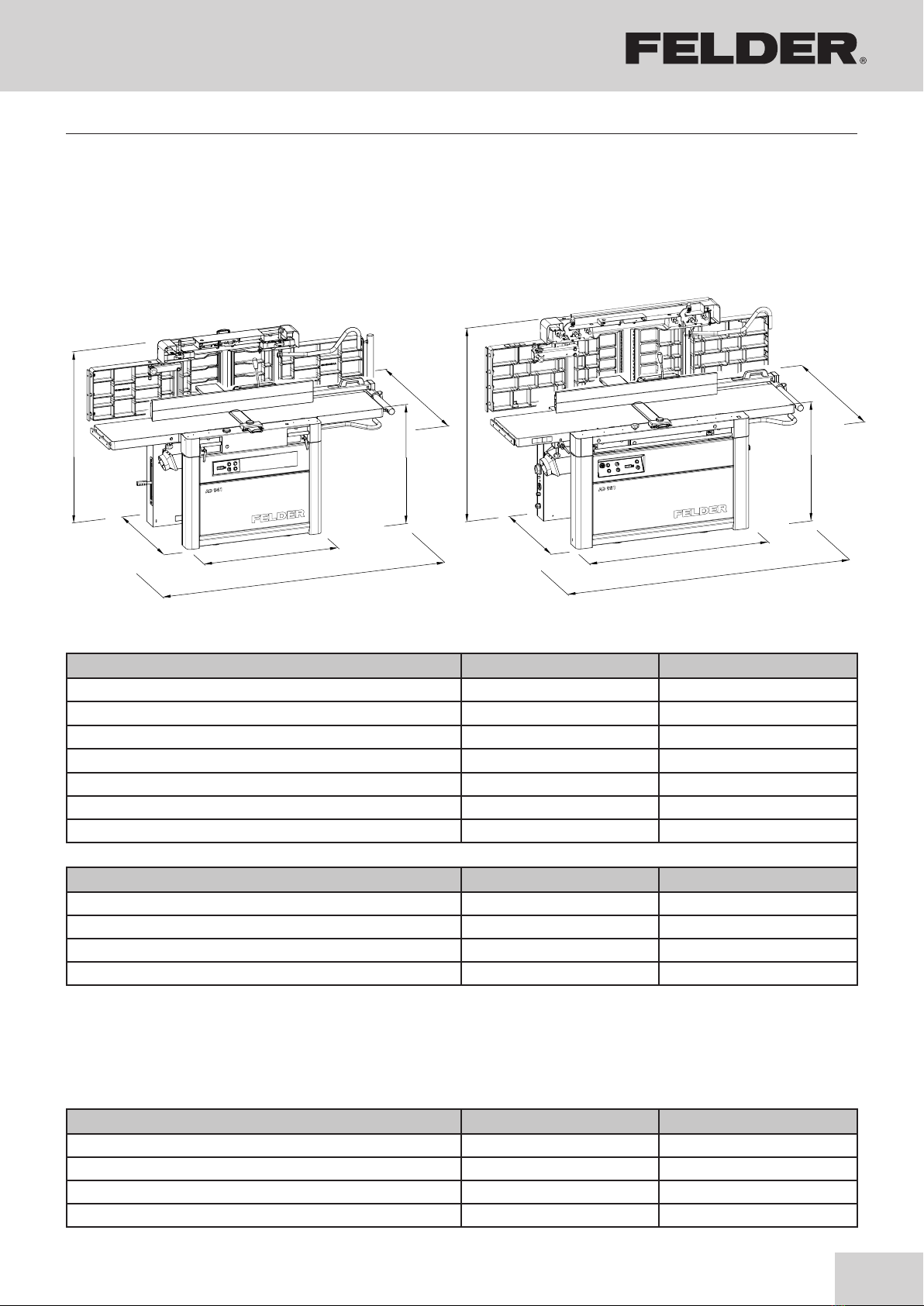
A 941 / AD 941 AD 951
Planer-Thicknesser
A 941 / AD 941 / AD 951
A 941 / AD 941 AD 951
Dust extraction outlet, Ø 120 mm 140 mm
Air speed 20 m/s 20 m/s
Vacuum Min. 590 Pa 500 Pa
Volume flow Min. 814 m³/h 1110 m³/h
Machine A 941 / AD 941 AD 951
Base dimensions A x B 1220 x 725 mm 1430 x 845 mm
Total height C896 mm 896 mm
Total height C1 (Thickness planing) 1510 mm 1650 mm
Overall width D Max. 1360 mm Max. 1480 mm
total length E2360 mm 2400 mm
Net weight *) 610 kg 900 kg
Operating/room temperature +10° to +40°C +10° to +40°C
Machine including packaging A 941 / AD 941 AD 951
length x Width x Height 2300 x 1200 x 1100 mm 2300 x 1200 x 1100 mm
Transport width min. 740 mm 850 mm
Weight (approx.)* 660 kg 950 kg
Storage temperature –10° to +50 °C –10° to +50 °C
*) with average-sized equipment
4 Technical data
Fig. 4-1: Dimensions
4.1 Dimensions and weight
4.2 Dust extraction
Technical data

16
Planer-Thicknesser
A 941 / AD 941 / AD 951
Machine A 941 / AD 941 AD 951
Cutterblock diameter (knife flight)-Ø 88 mm 119 mm
Number of knives *) 2 / 3 / 4 / Silent Power 4 / Silent Power
Speed 50/60 Hz 4700 min-1 4700 min-1
*) depending on the equipment
Machine AD 941 AD 951
Thicknesser table length 620 mm 900 mm
Thicknessing width 404 mm 504 mm
Thicknessing height Min./Max. 3 / 250 mm 3 / 254 mm
Feed rate (AD 951: infinitely variable) 6 + 12 m/min 4–16 m/min
Depth of cut Max. 5 mm 5 mm
Machine A 941 / AD 941 AD 951
Planer table length 1080 mm 1095 mm
Total planer table length 2200 mm 2252 mm
Surface planing width 410 mm 510 mm
Planer fence - tiltable from 90° to 45° 90° to 45°
Fence guide 170 x 1300 mm 170 x 1300 mm
Depth of cut Max. 5 mm 5 mm
Alternating-current motor Three-phase current motor
Motor voltage 1x 230 V 3x 230 V / 3x 400 V
Motor frequency 50/60 Hz 50/60 Hz
System of protection IP 55 IP 55
Motor power S6-40 %*)
Standard 3 kW 4 kW
Option - - - 5,5 kW, 7,35 kW
Option AD 951 - - - 10 kW
Geared motor AD 951 0,55 kW
*) S6 = operation under load and intermittent service; 40% = relative operating factor
4.6 Planer unit
4.3 Electrical connection/Drive motor
4.4 Cutterblock
4.5 Thicknesser unit
The actual values can be found on the data plate.
Technical data

17
90 / 84*) 94 / 85*) 99 / 91*) 97 / 92*)
83 / 74*) 86 / 73*) 88 / 83*) 91 / 82*)
97 / 83*) 94 / 83*) 101 / 91*) 97 / 91*)
82 / 69*) 79 / 71*) 87 /79*) 83 /76*)
81 / 69*) 85 / 72*) 84 / 78*) 88 / 77*)
Planer-Thicknesser
A 941 / AD 941 / AD 951
Idle Working
Surface planing width in mm --> 410 510 410 510
Sound power level - L WA
(EN ISO 3746)
Workplace emissions values - L pA
(EN ISO 11202)
*) = Reduced noise emission with the Silent-POWER® cutterblock
Idle Working
Thicknessing planing width in mm --> 410 510 410 510
Sound power level - L WA
(EN ISO 3746)
Workplace emissions values - L pA
(EN ISO 11202)
Working position 1 (feeder-side)
Working position 2 (receiver-side)
*) = Reduced noise emission with the Silent-POWER® cutterblock
Technical data
4.7 Noise emission
The specified values are emission values and therefore
do not represent safe workplace values. Even though a
relationship exists between particle emission and noise
emission levels, an inference cannot be made about
whether additional safety measures need to be imple-
mented. Factors which can significantly affect the emis-
sion level that presently exists at the workplace include
duration of the effect, characteristics of the workspace,
and other ambient influences. The permissible workplace
values may also differ from country to country. Neverthe-
less, this information is provided to help the operator bet-
ter assess hazards and risks. Depending on the location
of the machine and other specific conditions, the actual
noise emission values may deviate significantly from the
specified values.
Note:
In order to keep noise emission to a minimum, be sure to always use sharpened planer knives.
Hearing protection must be worn, it is however, not a substitute for correctly sharpened planer knives.
Note:
All values in dB(A) and with a measurement uncertainty factor of 4 dB(A).
The measurement results are in accordence to:
ISO 7960:1995, Annex B (Surface planing)
ISO 7960:1995, Annex C (Thickness planing)
Acoustic power level according to EN ISO 3746
Emission values at the workplace according to EN ISO 11202
Measurement conditions / Additional data: EN 19085-1, Chapter 7.2.2
18
!
BP
/
/
#
#
#
"
"
$
$
!
%
%
BP
BQ
BQ
&
&
*
*
)
BL
BL
BM
BN
BO
ø 140 mm
ø 120 mm
Planer-Thicknesser
A 941 / AD 941 / AD 951
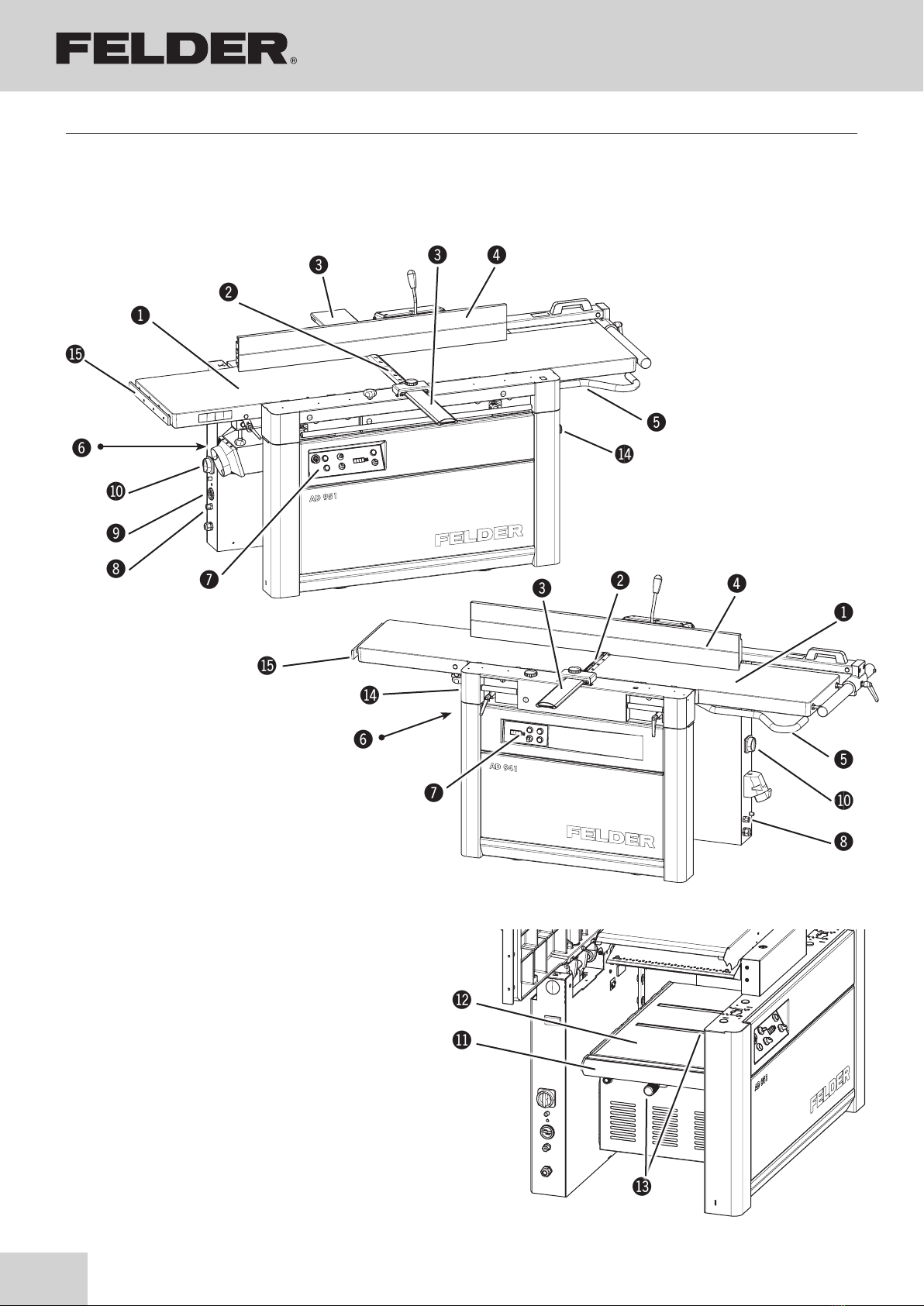
Fig. 5-1: Overview - AD 951
Fig. 5-2: Overview - A 941 / AD 941
Fig. 5-3: Overview - Thicknesser unit
!Planer unit
"Cutterblock
#Cutterblock cover
$Planer fence
%Adjusting the depth of cut
&Dust extraction outlet, Ø
/Control panel
(Potential-free contact
)Operating hour meter (Option)
BLMain switch
BMWorkpiece roller (Option)
BNThicknesser table
BOUnder table rollers (Option)
BPEMERGENCY-STOP button
AD 941 - Option
BQTable extension clamping system “F”
(Option)
5 Assembly
5.1 Overview
Assembly
19
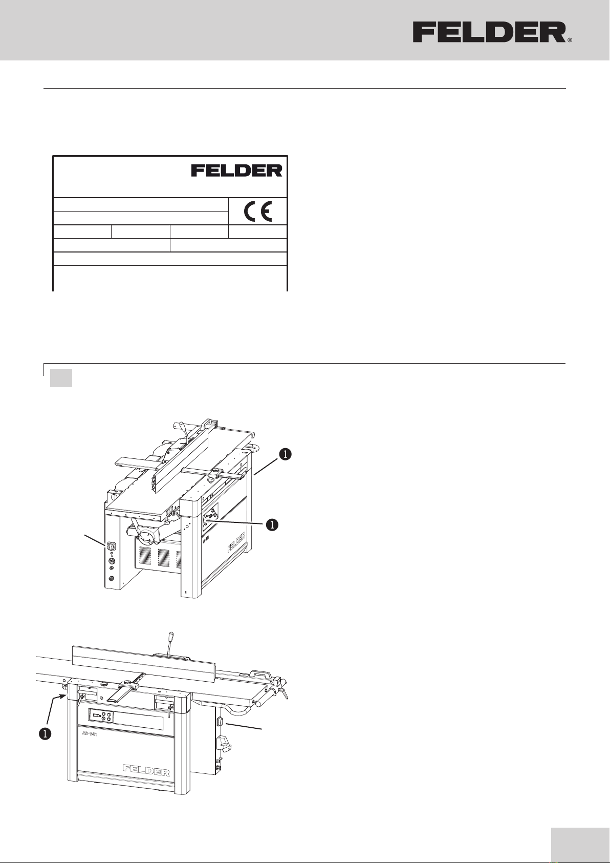
PH: HZ: A:
Baujahr / year of construction / ANNEE DE CONSTR.:
KW:
V:
NR.:
TYPE :
XXX-XXX/XX-XX
XXXXXXXX
20xx
KR-Felder-Straße 1, 6060 HALL in Tirol
AUSTRIA, Tel. +43 (0) 5223 58500
350 6.7400
4.0 S1
!
!
"
"
A 941 / AD 941
AD 951
!
!
Planer-Thicknesser
A 941 / AD 941 / AD 951
1. The main switch is located on the back of the
machine. This switch can be secured with 3 padlocks
if required.
2. The machine is equipped with a motor protection
device that switches the machine off in the event of
an overload.
3. AD 951 (Safety regulations)
The machine is equipped with emergency stop
buttons. They must be unlocked before the machine
can be started.
!EMERGENCY STOP button
AD 941 - Option
"Main switch
5.2 Data plate
The data plate displays the following specifications:
• Model designation
• Machine number
• Voltage
• Phases
• Frequency
• Power
• Electricity
• Year of construction
• Manufacturer information
Fig. 5-4: Data plate
5.3 Electrics
Fig. 5-5: Electrics
Attention! Your machine is equipped with safety break switches. The planer arbor can only run when the
joiner tables are closed or the extractor hood is tilted up.
Assembly
20
!
"
Planer-Thicknesser
A 941 / AD 941 / AD 951
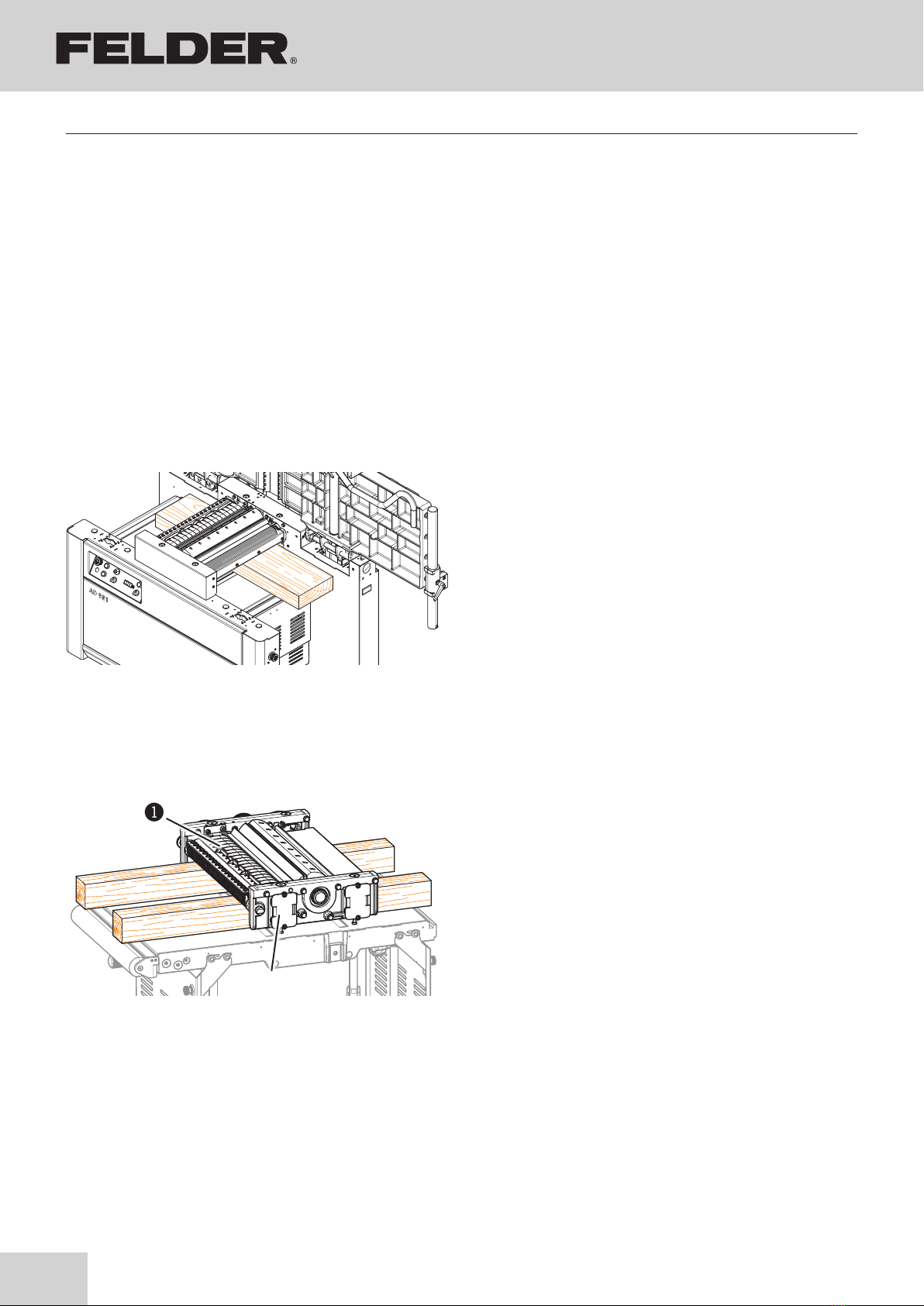
5.6 Pressure beams
The pressure beams combined with the rubber or seg-
mented infeed roller serves to machine simultaneously
workpieces of differing width. (The maximum difference
between workpiece to workpiece measures 1 mm.).
!Pressure beams
"Rubber infeed roller
Fig. 5-7: Pressure beams
5.5 Rubber in- and outfeed rollers (option)
Fig. 5-6: Infeed and outfeed rollers
Rubber in- and outfeed rollers ensure that thin workpiec-
es can be easily handled.
“Changing rubber in- and outfeed rollers”
See chapter entitled >Maintenance and servicing<
5.4 Automatic braking system
Your machine is equipped with an automatic braking
unit.
The brake is a maintenance-free DC braking unit. All
necessary adjustments are done by FELDER KG.
The DC braking unit must be controlled regularly. The unit
must stop with the clamped tool after 10 seconds.
Please contact the FELDER KG service department, if prob-
lems or a fault- function should occur!
Assembly
This manual suits for next models
2
Table of contents
Other Felder Planer manuals


