Fema KMC 47 Series User manual

THIS MANUAL TO ACCOMPANY MACHINE
OPERATOR’S MANUAL
PART NO. 47-OM-01
PRINTING DATE: MAY 2019
47-SERIES
4700, 4750, 4755 & 4760
DISC MOWER CADDY

3-YEAR
WARRANTY POLICY
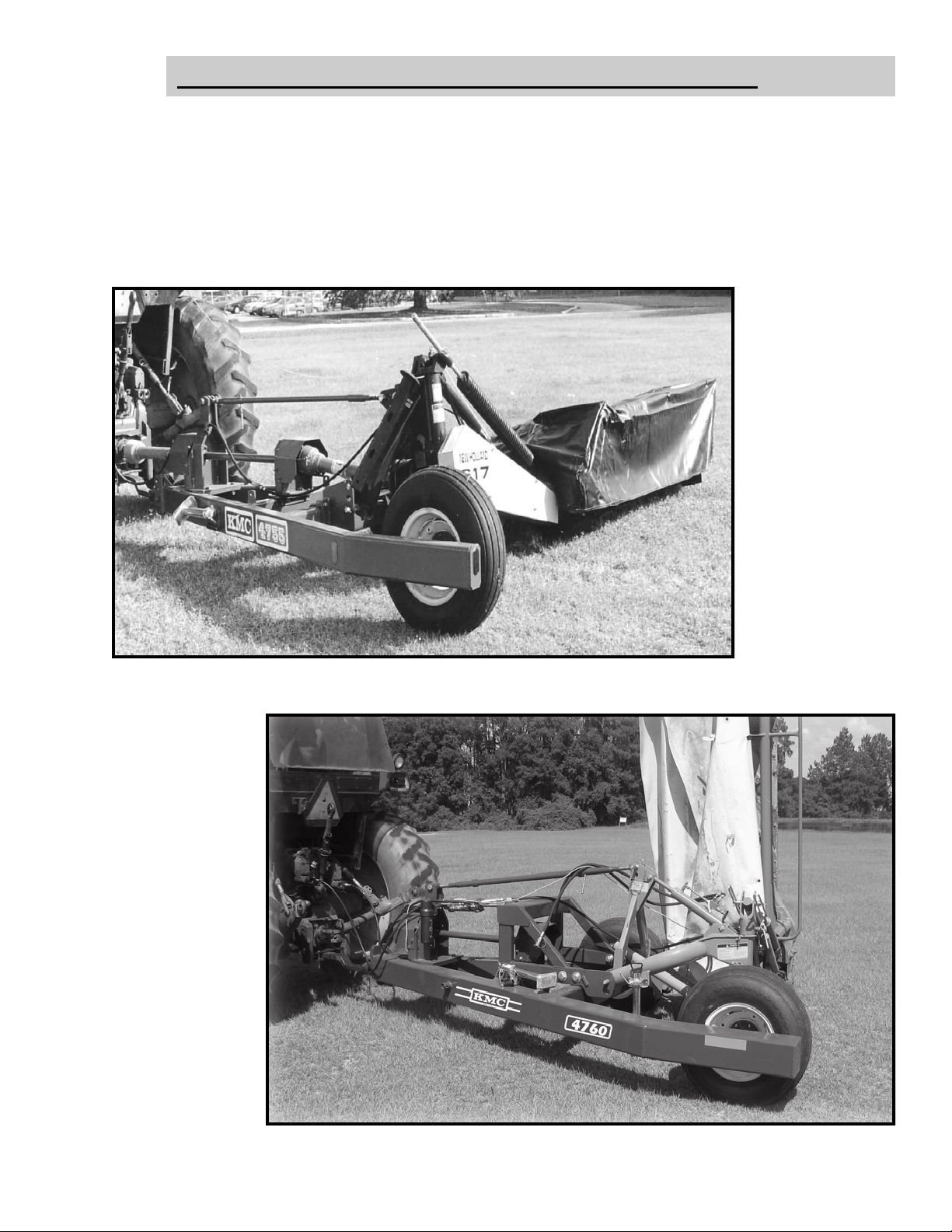
KELLEY MANUFACTURING COMPANY (KMC) warrants that Disc Mower
Caddy’s sold to the original purchaser shall be free of any defects in material and
workmanship if used under normal operating conditions. The warranty period
begins on the date of purchase by the retail customer and ends thirty-six
(36) months thereafter. KMC’s sole responsibility is to repair and/or replace the
defective part or parts at no cost to purchaser. This remedy is the SOLE AND
EXCLUSIVE REMEDY of purchaser.
The purchaser must fill out and return the warranty registration form found in the
front of the operator’s manual. Failure to return the warranty registration form within
30 days shall result in the goods being sold “AS IS”, and all warranties shall be
excluded.
1. This warranty shall not apply to those items that are by nature worn in normal
service.
2. Items such as tires, bearings, wheel hubs, hydraulic cylinders, drivelines and all
other items warranted by the original manufacturer are warranted only to the
extent of their individual manufacturer warranty, and KMC is not warranting any
of the said items.
3. Warranty shall not apply for any damage caused by foreign objects that enter the
disc mower caddy.
4. Warranty shall not apply for any damage caused by improper lubrication or lack
of service.
5. Warranty shall not apply for any damage resulting from transport of the disc
mower caddy after delivery by the dealer.
6. All warranty claims must be made through a KMC licensed dealer, and a
warranty form request must be submitted to KMC within 30 days of failure of the
warranty provision shall be unenforceable against KMC.
No agent or person has authority to change or add to this warranty as written.
THE ABOVE IS THE ONLY WARRANTY MADE BY KMC AND IS MADE
EXPRESSLY IN LIEU OF ALL OTHER WARRANTIES, EXPRESSED OR IMPLIED.
KMC MAKES NO WARRANTY OF MERCHANTABILITY AS TO ANY GOODS
MANUFACTURED BY KMC AND FURTHER, KMC DOES NOT WARRANT ANY
SUCH GOODS AS SUITABLE FOR ANY PARTICULAR PURPOSE TO THE
RETAIL CUSTOMER. THE SUITABILITY OF GOODS FOR ANY PURPOSE
PARTICULAR TO THE CUSTOMER IS FOR THE CUSTOMER, IN HIS SOLE
JUDGEMENT, TO DETERMINE. KMC FURTHER MAKES NO WARRANTIES
WITH RESPECT TO ITS MANUFACTURED GOODS THAT WOULD NORMALLY
BE DISCLOSED BY AN EXAMINATION. THIS IS THE FULL AND FINAL
EXPRESSION OF ALL WARRANTY LIABILITY OF KMC. NO OTHER
WARRANTY, EITHER EXPRESSED OR IMPLIED, SHALL BE ENFORCEABLE
AGAINST KMC.
Kelley Manufacturing Co.
80 Vernon Drive / Zip 31794 P.O. Drawer 1467 / Zip 31793 Tifton, GA

1
DISC MOWER CADDY OWNERS MANUAL
Table of Contents:
FORWARD
Introduction ·················································································· 2
To the Purchaser ············································································ 2
Models Covered in This Owner’s Manual ············································· 3
Pre-Operational Check List ······························································· 4
SAFETY
Symbol Information········································································· 5
Safety Decals·················································································· 6
Retail Customers Responsibility under the KMC Warranty ······················ 7
Safety Procedures ··········································································· 7-8
ASSEMBLY SET-UP
General ························································································ 9-12
Overhead Layouts ·········································································· 13-17
Drawbar Position ············································································ 18
Implement Hitch············································································· 18
Mower Driveline ············································································· 19
Positioning of Mower on Caddy ·························································· 19
Attaching Mower ··········································································· 20-23
Adjusting Angle of Mower ································································ 23
Miscellaneous················································································· 23
Before Operation ············································································ 24
OPERATIONAL SET-UP
Tractor Preparation
Front End Preparation ····························································· 25
Horse Power Requirements ······················································· 26
Sway Blocks ·········································································· 26
Drawbar Position···································································· 26
MAINTENANCE

2
Serial # Tag Location
FORWARD
INTRODUCTION:
TO THE PURCHASER
This KMC Disc Mower Caddy has been carefully designed and manufactured to give
years of dependable service. In order to operate it efficiently and maintain it properly, please
read the instructions within this manual thoroughly.
Some components of this machine are labeled left or right. The notations are determined by
standing behind the implement and facing the direction of forward travel.
After reading this Operator’s Manual, Please keep it for reference each season.
To insure procurement of the proper repair parts, please record your machine’s Model Number,
Serial Number, and Purchase Date as shown below:
Model No._______________________
Serial No.________________________
Purchase Date ___________________
The KMC Disc Mower Caddy is designed to provide long life to the components of the caddy
and mower by providing smooth, consistent power, whether the tractor is turning or running straight
forward. Optional lift kits are available for some mowers. Also optional 300 pound weight can be add-
ed to the side of the mower to give additional counter balance and to improve stability with bigger Disc
Mowers Models.

3
MODELS COVERED IN THIS OWNER’S MANUAL:
(MODEL 4700SH)
MOWER CADDY
WITHOUT LIFT KIT
(MODEL 4700LK)
MOWER CADDY
WITH LIFT KIT
(MODEL 4750SH)
MOWER CADDY
WITHOUT LIFT KIT
(MODEL 4750LK)
MOWER CADDY
WITH LIFT KIT
(MODEL 4755SH)
MOWER CADDY
WITHOUT LIFT KIT
(MODEL 4760LK)
MOWER CADDY
WITH LIFT KIT
(NOT FOR USE WITH CAT
II QUICK HITCH MOWERS)
(MODEL 4755LK)
MOWER CADDY
WITH LIFT KIT
(MODEL 4760SH)
MOWER CADDY
WITHOUT LIFT KIT

4
All safety and operating procedures reviewed
All hardware checked for tightness
Hitch connection to implement information reviewed
Field adjustment procedures reviewed
Lubrication information reviewed
Machine fully lubricated
Warranty information reviewed
PRE-OPERATIONAL CHECKLIST:

5
This safety alert symbol is used throughout this manual to identify safety messages.
When you see this symbol, read the message which follows as it will advise you of
possible injury.
BEING SAFETY CONSCIOUS IS GOOD BUSINESS!
SAFETY
This symbol indicates an imminently hazardous situation
that, if not avoided, will result in death or serious injury.
This symbol indicates a potentially hazardous situation that,
if not avoided, could result in death or serious injury. It may
also be used to alert against unsafe practices.
This symbol indicates a potentially hazardous situation that,
if not avoided, may result in minor or moderate injury. It may
also be used to alert against unsafe practices.
REMEMBER THINK SAFETY!
SYMBOL INFORMATION
Is used for instruction on operating, adjusting, or servicing a
machine.
(RED)
(ORANGE)
(YELLOW)
(GREEN
OR
BLACK)

6
DO NOT GO NEAR LEAKS
• High pressure oil easily punctures skin
causing serious injury, gangrene or death.
• If injured, seek emergency medical help.
Immediate surgery is required to remove
oil.
• Do not use finger or skin to check for
leaks.
• Lower load or relieve hydraulic pressure
before loosening fittings.
SAFETY DECALS
The Safety decals that follow are associated with the implement covered in this owner’s manual. They
should be reviewed and associated with where they are applicable on the implement being covered.

7
RETAIL CUSTOMERS RESPONSIBILITY UNDER THE KMC WARRANTY:
The retail customer’s responsibilities are:
1. To read the Operator’s Manual and operate the Disc Mower Caddy in accord-
ance with the instructions given in this manual.,
2. To inspect the Disc Mower Caddy daily, lubricate as specified and repair or
replace parts as needed, especially when continued use would cause damage or
excessive wear to other parts.
3. To maintain and keep in place all safety shields, decals and devices.
4. When warranty service is necessary, it is the customer’s responsibility to deliver
the machine to the KMC dealer from which it was purchased. Warranty repairs
should be submitted to the dealer within thirty (30) days of failure.
5. Dealer travel to the machine or hauling the machine to his shop for the purpose
of performing warranty service is not allowed under KMC warranty. It is a cost
to be paid for by the retail customer. Any arrangement whereby the dealer
agrees to absorb all or part of this cost is strictly between the dealer and the
retail customer.
2.Do not permit anyone to ride on the machine at any time.
3. Before starng or operang the machine, make a walk-around inspection and
check for obvious defects such as loose mounting bolts and damaged compo-
nents. Correct any deficiencies before starting. (The equipment must be
properly maintained and guarded and must be suitable to performing its
1. All persons operating this piece of equipment should READ the owner’s manu-
al. (In addition, the operator’s manual & decals on the mower itself warn
you of further danger & should be READ & observed closely.)
task.)
4. Keep all persons a safe distance away from all sides of the machine while it is
in operation.
SAFETY PROCEDURES:
Safety and performance are the primary
objectives of the designers of KMC
equipment. Safety features have been
incorporated into this machine where possible
and warnings given in other areas. For your
safety, PLEASE read and observe the
following safety procedures.

8
5. Do not allow children to operate the Disc Mower Caddy . Only experienced
tractor operators should operate the tractor when the Disc Mower Caddy is
in use.
6. Stay clear of hydraulic lines, as they maybe under extreme pressure or heat.
7. Drive safely during transport; excessive speed while turning or on rough
ground could cause damage to the Disc Mower Caddy and/or cause the tractor
to tip over. (Maximum speed of implement should never exceed 20 mph on
highway and 10 mph off-highway.)
Do NOT transport Disc Mower Caddy with optional weight rack mounted un-
less mower is attached.
8. Make sure hitch components are aached securely before operating or
transporting.
9. Use ashing warning lights when on highways, except where prohibited by
law.
10. Disengage PTO, apply parking brake, and stop tractor engine before
dismounting tractor. Allow mechanisms to stop completely before cleaning,
working, or adjusting on machine. Even when the tractor is stationary, you
should make sure it is properly secured and made safe by following the
Safe Stop procedure:
1. Handbrake/Footbrake on
2. Controls in neutral/park
3. Engine off
4. Key out
11. Keep hands, feet and clothing away from moving parts.
12. Make sure everyone is clear of machine before starng tractor or operating
machine.
13. Observe all safety decals located on machine. Replace them if they become
damaged.
HIGH VOLTAGE SAFETY ACT
Georgia Law requires that anyone operating equipment within 10 feet of an overhead
high voltage line of more than 750 volts, must contact the Utilities Protection Center
(UPC) by telephone at least 72 hours before commencing the work. For more infor-
mation call (811), toll free (1-800-282-7411) or visit on the web “www.gaupc.com.
Please contact your local power company about laws before operating near high volt-
age lines.

9
DISC MOWER CADDY BASIC FEATURES
Throughout this manual we will be discussing various features and components of the KMC
Disc Mower Caddy. References to various components for adjustments, settings, performance, and
lubrication are made. The following diagram will help in identifying these components.
ASSEMBLY SET-UP
GENERAL:
4760 CADDY (NON-LIFT KIT)
DRIVELINE
MAST
MAIN FRAME
REAR SUPPORT
TOP LINK
INPUT SHAFT
JACKSTAND
LOWER HITCHES
OPTIONAL
WEIGHT RACK*
4760 CADDY (LIFT KIT)
(NOT FOR USE WITH CAT II QUICK HITCH MOWERS)
OPTIONAL
WEIGHT RACK*
TOP LINK
LOWER HITCHES
REAR SUPPORT
LIFT KIT
TOP LINK
MAIN FRAME
JACKSTAND
INPUT SHAFT
DRIVELINE
MAST
* Do NOT mount weight rack until after mower is attached.

10
CARE SHOULD BE TAKEN DURING SET-UP AND ASSEMBLY OF THIS
PRODUCT. DEATH OR SERIOUS INJURY COULD OCCUR IF PROPER
STEPS ARE NOT TAKEN TO FULLY SECURE THE UNIT WHEN WORKING
UNDERNEATH IT. FOR YOUR SAFETY, ENSURE THE UNIT IS PROPERLY
SUPPORTED BY LOWERING THE JACKSTAND SUPPORTS THAT HAVE
COME ASSEMBLED WITH IT, OR PROPERLY SECURE THE UNIT WITH
ANY HOISTING DEVICES BEFORE ATTEMPTING ANY FURTHER SET-UP
OF THIS PRODUCT. ANY HOISTING DEVICES SHOULD BE RATED TO
FULLY SUPPORT THE LOAD OF THE UNIT BEING LIFTED.
WARNING
REAR JACKSTANDS WHEEL BLOCKS

11
SAE GRADE 5
SAE GRADE
BOLT TORQUE CHART
Before set-up and assembly can be completed ensure that all hardware is in place and fully tightened.
Refer to the Bolt Torque Chart below for proper torque values.
! IMPORTANT !

12
CADDY SPECIFICATIONS
Overall Length - 146 inches
Overall width - 80 inches
85 inches (4760 MODEL)
Weight - 1300 lbs (4700 MODEL)
1400 lbs (4750 MODEL) w/ Lift Kit add 100 Lbs
1500 lbs (4755SH MODEL)
1650 lbs (4755LK MODEL)
1650 lbs (4760SH MODEL)
1750 lbs (4760LK MODEL)
300 lbs (4760 Weight Rack)
Tires - 11L x 15SL
Operating Speed - 540 RPM
Hitch Specifications - Standard Hitch Version: CAT II 3-Point, CAT II Quick Hitch;
Lift Kit Version: CAT II 3-Point ONLY

13
OVERHEAD LAYOUTS:
NOTE: The original Model 4700 Caddy used the Mower’s Driveline upfront between the
tractor and Caddy.
4700 SERIES
LOCKING
COLLAR
ROTATION
GREASE FITTING
TURNED TO
BOTTOM
LOCK BEARING COLLAR IN
COUNTER-CLOCKWISE
DIRECTION FROM FRONT
OF CADDY
MOWER’S
DRIVELINE
HERE
SET LT HAND SIDE HITCH
TO DIMENSION SHOWN.
32 7/16”
(REF)
9 7/8”

14
5 1/16”
ASSEMBLED LOCATION
OF JACKSHAFT
4755LK SERIES
TO HOSE
FROM MOWER
SWIVEL END
OF HOSE
TO
CADDY
MAST
LOCKING
COLLAR
ROTATION
DRIVELINE
PROVIDED
BY KMC
LOCK BEARING
COLLAR IN
COUNTER-
CLOCKWISE
DIRECTION
FROM FRONT
OF CADDY.
MOWER’S DRIVELINE
STAYS ATTACHED TO
MOWER.

15
4755SH SERIES
5 1/16”
ASSEMBLED LOCATION
OF JACKSHAFT
32 7/16”
(REF)
9 7/8”
TO HOSE
FROM MOWER
GOES TO MAST
PIN ON MOWER
LOCKING
COLLAR
ROTATION
MOWER’S DRIVELINE
STAYS ATTACHED TO
MOWER.
LOCK BEARING
COLLAR IN
COUNTER-
CLOCKWISE
DIRECTION
FROM FRONT
OF CADDY.

16
4760 SERIES
*REFER TO YOUR DISC MOWER
OWNER’S MANUAL FOR THE
CORRECT HITCH PIN HEIGHT.
4760 CADDY (STD HITCH KIT)
9 7/8(SET LT HAND SIDE HITCH
TO DIMENSION SHOWN)
32 7/16(REF)
STD. HITCH LOCATION
5 1/8
ASSEMBLED LOCATION
OF FRONT JACKSHAFT
TO TRACTOR
REMOTE
TO HOSE
FROM MOWER
OPTIONAL
WEIGHT KIT

17
4760 CADDY (LIFT KIT)
(NOT FOR USE WITH CAT II QUICK HITCH MOWERS)
TO TRACTOR
REMOTE #1
TO TRACTOR
REMOTE #2
TO HOSE
FROM MOWER
OPTIONAL
WEIGHT KIT
NOTE:
LIFT KIT VERSIONS OF THE DISC MOWER CADDY ARE NOT FOR USE
WITH CAT II QUICK HITCH ONLY MOWERS. THEY ARE FOR USE WITH
CAT II 3-POINT MOWERS, WHERE THE DISTANCE BETWEEN THE LOWER
HITCH POINTS AND THE MAST POINT IS AT LEAST 19 INCHES.

18
PTO SHAFT
GROUND LINE
DRAWBAR
Drawbar Position
This distance will maintain the proper relationship for working driveline angles through
turns and help improve the life of the driveline
Implement Hitch
The tractors drawbar should be positioned at a distance of 14 inches from the end of
the PTO shaft to the drawbars hitch pin hole. (Standard distance for 540 PTO Drives)
(Tractor PTO and Drawbar Hitch Pin Hole Distance)
This implements tongue/pull
hitch is designed to give 4 different
hitching positions.
In order for the Caddy to oper-
ate properly at all times, it is recom-
mended that the proper hitch height
be selected to keep the Main Frame
and Caddy parallel with the ground.
After drawbar and tongue/pull hitch
are positioned correctly, the Tractor
and Caddy can be hitched together.
(Adjustable Tongue/Pull Hitch)
This manual suits for next models
4
Table of contents
Other Fema Farm Equipment manuals
Popular Farm Equipment manuals by other brands

Kverneland
Kverneland Vicon Andex 774 operating manual

Brillion
Brillion Zone Commander ZM3302 Operator's manual

Jumil
Jumil 3090PD instruction manual

M K Martin Enterprise
M K Martin Enterprise SCIC250 Owner's/operator's manual

MASCHIO GASPARDO
MASCHIO GASPARDO ADMIRAL Use and maintenance

Raven
Raven SC1 installation manual