Fencee mini DUO MD03 User manual
+420 730 893 828
1
www.fencee.eu
EN
USER MANUAL
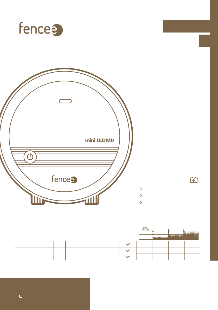
fencee mini DUO MD03
fencee mini DUO MD06
fencee mini DUO MD10
230V ~ /12 V
STORED
ENERGY
OUTPUT
ENERGY
OUTPUT
VOLTAGE
OUTPUT
VOLTAGE 500 Ω
SWITCHING
ON / OFF
fencee mini DUO MD03 0,5 J 0,3 J 9 000 V 3 000 V
fencee mini DUO MD06 0,9 J 0,6 J 9 500 V 3 500 V
fencee mini DUO MD10 1,4 J 1 J 10 000 V 4 000 V
12 km 5 km 3 km 0,5 km
21 km 7 km 5 km 1 km
30 km 12 km 7 km 2 km
Electric fencing

2
In Lanškroun July 14th, 2022
Ing. Jan Horák
Executive Head of the Company
Tel.: +420 730 893 828
info@fencee.eu
www.fencee.eu
DECLARATION OF CONFORMITY
ENERGIZERS FOR ELECTRIC FENCES
fencee mini DUO MD03, fencee mini DUO MD06
fencee mini DUO MD10
Test Report No.:
40 745
Manufacturer:
VNT electronics s.r.o.
Dvorská 605, 563 01 Lanškroun
IČO: 64793826
declares that the below listed products:
are in accordance with requirements of standards
and regulations relevant for given type of devices:
Products are safe under condition of their conventional use
in accordance with instructions for use. Declaration
of conformity is issued pursuant to these materials
Issued by accredited Státní zkušebnou strojů a.s.,
Třanovského 622/11, 163 00, Praha 6.
This declaration is issued at explicit responsibility of the manufacturer.
2014/35/EU
2014/30/EU

3
Thank you for purchasing the product of the company VNT electronics s.r.o.
The equipment conforms to safety regulations in accordance with
valid legislation as well as relevant EU (CE) regulations.
We also ask you to read these instructions for use before using the device
carefully and to keep it for possible application in the future.
Electric fence must be constructed so that persons are protected against
unintentional contact with pulses conductors under normal operating conditions.
From the point of view of legislation, especially the standard ČSN EN 60335-2-76 ed.2
(Electric appliances for domestics and similar purposes – Safety – Part 2-76: Special
requirement on energizers for electric fences) and norm 2014/35/EU - 2014/30/EU.
1. CONTENT
1Content . . . . . . . . . . . . . . . . . . . . . . . . . . . . . . . . . . . . . . . . . . . . . . . . . . . . . . . . . . . . . . . . . . . . . . . 3
2Important recommendations . . . . . . . . . . . . . . . . . . . . . . . . . . . . . . . . . . . . . . . . . . . . . . . . . . . . . . 4
3Package contents. . . . . . . . . . . . . . . . . . . . . . . . . . . . . . . . . . . . . . . . . . . . . . . . . . . . . . . . . . . . . . . . . . . . . 4
4Function electric fence . . . . . . . . . . . . . . . . . . . . . . . . . . . . . . . . . . . . . . . . . . . . . . . . . . . . . . 5
5Introduction . . . . . . . . . . . . . . . . . . . . . . . . . . . . . . . . . . . . . . . . . . . . . . . . . . . . . . . . . . . . . . . . . . . . . . . . . . . . . . . 6
6Product description . . . . . . . . . . . . . . . . . . . . . . . . . . . . . . . . . . . . . . . . . . . . . . . . . . . . . . . . . . . . . . . . . . . . . . 6
7Ready to use . . . . . . . . . . . . . . . . . . . . . . . . . . . . . . . . . . . . . . . . . . . . . . . . . . . . . . . . . . . . . . . . . . . . . . 7
8Control . . . . . . . . . . . . . . . . . . . . . . . . . . . . . . . . . . . . . . . . . . . . . . . . . . . . . . . . . . . . . . . . . . . . . . 10
9Explanation of LED indicating lights and bargraph indicator . . . . . . . . . . . . . . . . . . . . 10
10 Safety guidelines . . . . . . . . . . . . . . . . . . . . . . . . . . . . . . . . . . . . . . . . . . . . . . . . . . . . . . . 11
11 Troubleshooting . . . . . . . . . . . . . . . . . . . . . . . . . . . . . . . . . . . . . . . . . . . . . . . . . . . . . . . . . 14
12 Guarantee . . . . . . . . . . . . . . . . . . . . . . . . . . . . . . . . . . . . . . . . . . . . . . . . . . . . . . . . . . . . . . . . . . . . . . . . . . . 15
13 Technical parameters . . . . . . . . . . . . . . . . . . . . . . . . . . . . . . . . . . . . . . . . . . . . . . . . . . . . . . 15

4
We recommend that this manual is read thoroughly and fully
understood before using the device and that it is retained for
future reference!
2. IMPORTANT RECOMMENDATIONS
•
The energizer will provide better protection for your animals and land.
Local conditions and surroundings always aect the device function and for that reason the
manufacturer is not able to guarantee full protection against damage to the fence system.
• Use only the original adapter to supply the energizer – 14 V / 1 A. The supply voltage must
not exceed 16 V. 12 V controller must be used if the solar panel is used as the energizer must
not be connected directly to the panel.
• Switch o the energizer before carrying out any work on the electric fence system.
• Read thoroughly the Safety Guidelines paragraph.
• Strictly observe all safety guidelines during installation work.
• Do not connect the device on one fence system to another appliance.
Damage to all connected devices and appliances may occur in the event of lightning strike.
• The device may only be repaired by the manufacturer’s qualied personnel.
• Please dispose all waste in accordance with your country’s code of practice.
• Do not let the unconnected battery cable hang freely as the short circuit and the consequent
destruction of the energizer may take place.
3. PACKAGE CONTENTS
• Energizer fencee mini DUO MD
• Earthing cable
• Connecting cable to the fence system
• 14 V/1 A power supply adapter for mains connection
• Battery cable
• Warning sign
• 1 piece - installation self-tapping screws and rawlplugs
• User Manual

5
4. FUNCTION ELECTRIC FENCE
How the electric fence works?
Electric fence system consist from the energizer and fencing marked with posts and
conductors. The energizer creates regular high-voltage impulses that generate a voltage
between the conducting material and the ground. When an animal (or a person, vegetation
or similar) creates a connection between the ground and the conducting material, the circuit
is completed. Generated impulses are unpleasant, but not dangerous to people or animals as
they only act for a short period of time and results in the desired deterrent eect. The impulse
lasts for a matter of milliseconds. These fences serve not only to enclose an area, but also act
as a deterrent e.g. to protect against wild boars.
Benefits of electric fence systems:
• Electric fences are long-lasting, simple to put up and great value for money compared with
normal fences.
• It is easy to assembly and exible for using.
• Designed for guarding and protecting dierent animals.
• Compared to other fences, such as barbed wire, it does not cause any damage to the animals.
6High-voltage connecting cable
7Conductor
8Line connector
9Fixed post
10 Tensioner
11 Insulators
12 Flexible post
13 Warning sign
14 Gate
15 Insulator of gate
1Energizer
2ON/OFF button
3Earthing cable
4Anticorrosive earthing rod
5Lightning diverter
3
9
4
6
2
15
14
12
5
8
10
11
13
6
7
8
11
1

6
5. INTRODUCTION
fencee energizers mini DUO MD are suitable for short and vegetation unburdened fences.
Thanks to their power they can secure sucient tension along the entire length. An
integrated microprocessor operates the whole operation and he secures optimal power, due
to the condition of the fence system.
Combined energizers fencee mini DUO MD can be powered from mains 230 V, with use of
enclosed 14 V adapter or by suitable 12 V battery. Energizer can be runned only on one of the
listed power sources. Not on both at the same time.
During the operation of the fence, there is a continuous measurement of the fence load.
The output power of the fencee mini DUO MD is then automatically adjusted to maintain
the desired output voltage over the largest possible load range. This regulation signicantly
helps to save energy during using a quality fence with a low load. The LED indicator on the
front side of the energizer shows the operation of the source and also signals a possible fault
on the energizer.
The energizers fencee mini DUO MD oer a special Power save mode. You can switch the
energizer to a slower mode, the frequency of the pulses will be approximately twice as long,
and thanks to this you will signicantly save the battery. It is convenient to use for example,
when the animals are used to the energizer and respect it. Thanks to this mode, the energizer
can run on the battery for almost twice longer.
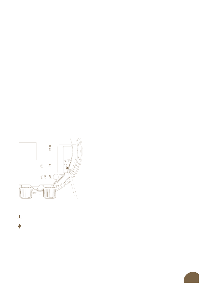
6. PRODUCT DESCRIPTION
Explanations of symbols shown on energizer
Earthing connection. Connect this connection to your earthing system.
Fence output with full voltage. Connect this connection to your fence system.
2
3
45
1
1Connector for connecting adapter ( 14 V /1A) or battery (12 V)
2LED control of connecting energizer and status indication
3ON / OFF switch button
4Earthing (black)
5Connection to fence system (red)

7
7. READY TO USE
Choose a place suitable for installation of energizer.
• Where you can achieve a good earthing.
• Which is distant enough from children and animals.
• Where energizer is well accessible.
• Where permanent water stream is avoided.
To mount energizer on wall, use attached screws, on which you can hang the energizer easily.
Assembly of energizer by using DIN rail
Energizer can be easily and practically mounted by using DIN rail and mounting bracket.
Set for assembly on DIN rail can be ordered as separate accessories.
3m
Energizer min. 20 cm
above the ground
MIN.
1m
Min. 10 metres from
next earthing point 3m
1. 2. 3.
8
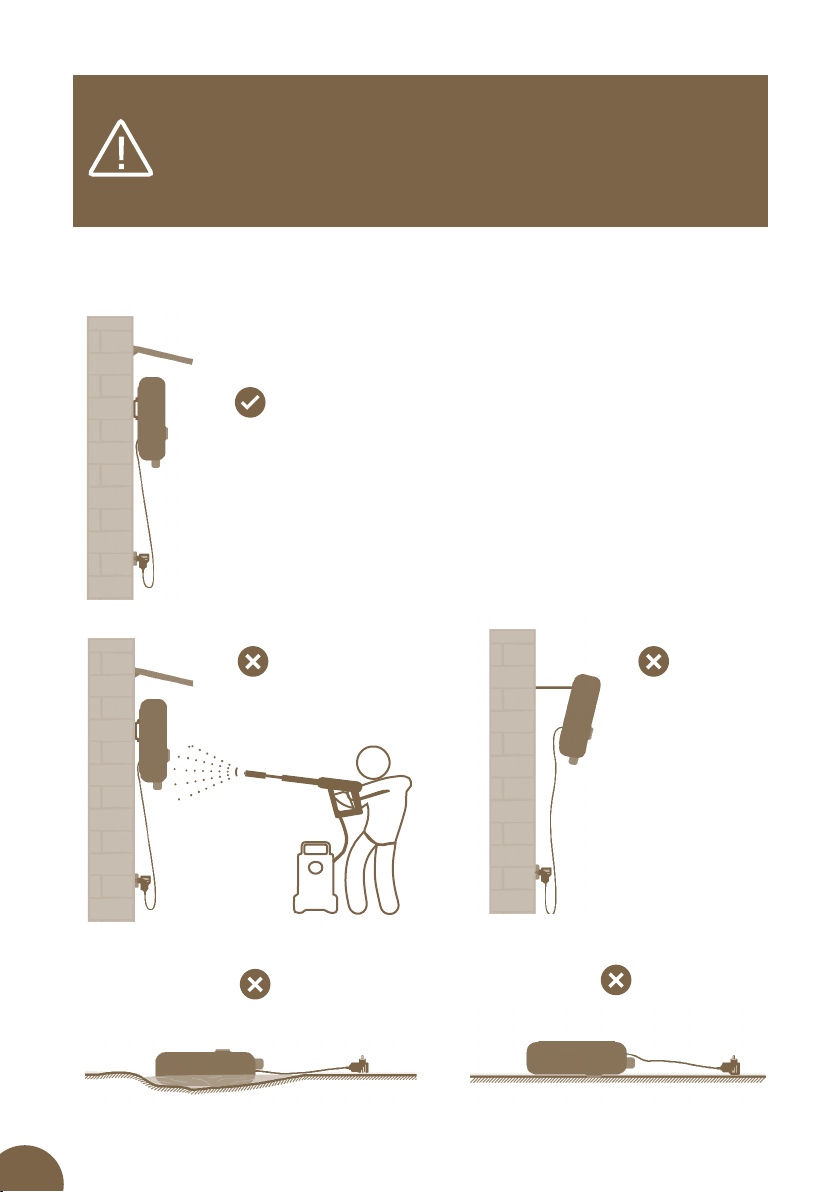
•Energizers must be installed in a dry place.
•Never put energizer on ground – in moist or wet environment.
•Fasten energizer by means of hanging screw or DIN rail with mounting bracket
in vertical position – at least 20 cm above ground.
•Never expose energizer to continuous water stream.
ON THE GROUND - IN A PUDDLE ON THE GROUND - UPSIDE DOWN
NEGATIVE
ANGLE
NEVER EXPOSE TO A
CONTINUOUS STREAM
OF WATER!
VERTICAL ON THE WALL
IDEALLY WITH A CANOPY
We recommend mounting on
DIN rail 80 mm (Art.No. 8043)
9
EARTHING
Correct earthing is very important because total function of the fence system is
dependent on it!
Beat earthing rod with corrosion protection into ground completely at place with maximum
and permanent humidity. On dry pieces of land or in case of soils with lower electric
conductivity, use one or several supplementary earthing rods (with length of minimum
of 1 m) and place them at distance of approximately 3 meters from each other.
Exceptions are fence system powered by battery energizer or working with low output.
Here minimum length of earthing rod of 50 cm is recommended.
Distance of at least 10 meters must be between earthing rod of the fence system and another
earthing system, for example earthing of a house, protective earthing of electric supply system
or earthing of violation alarm.
Do not connect the energizer to already existing earthing or to the the earthing
of another energizer. Each energizer must have its own earthing.
Connection of connectors
The mini DUO MD models have only one input connector to connect the power source.
Either for powering with an adapter from the mains or using a battery cable from 12 V battery.
Connection of the output terminals
Connect the black earthing clip with the earthing cable to the earthing rod.
Connect the red clip with the connecting cable to the fence.
Connector for connect
the adapter or battery.
10
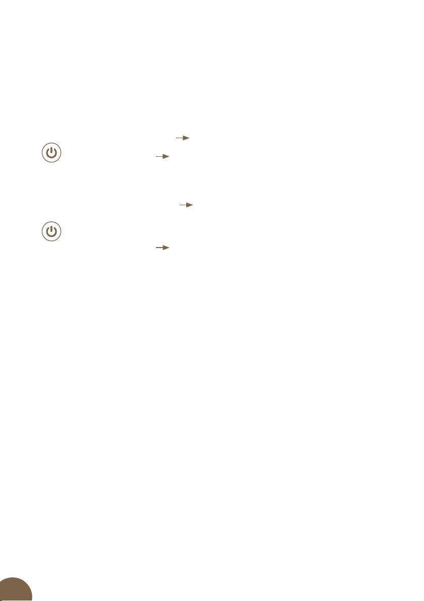
8. CONTROL
POWER SWITCHING ON/OFF SWITCH BUTTON
The large switch button is used for basic control. This button turns the energizer on and o
and it can be used to activate the Power save mode, i. e. to extend the interval between pulses.
After switching o and then switching on, the energizer remembers the last set power.
IN SWITCHEDOFF CONDITION OF THE ENERGIZER
long press of button (>2 s)
switching energizer on.
short press of button
no reaction.
IN SWITCHEDON CONDITION OF THE ENERGIZER
long press of button (>2 s)
manual switching between basic and Power
save mode (approximately 2x longer delay) – selectable by the user, for
example if it is necessary to save the battery
short press of button turning off the energizer.
9. EXPLANATION OF THE LED INDICATOR SIGNALS
LIGHT/FLASHING
FLASHING
It signals the operation and ashes in interval of the individual pulses.
RAPID DOUBLE FLASHING (red)
The battery voltage has dropped below 12 V.
RAPID SHORT FLASHING (red)
The energizer is switched o and the battery voltage is lower than 11,4 V.
COLOR
Blue
Operation in normal mode.
Purple
Power save mode, extended time between pulses.
Red
Indicates warning and error condition (for example battery voltage drop below 12 V)
or a fence voltage drop below 2.5 kV.
When the battery voltage drops below 11,6 V, a warning siren (beeping) is switched on. If the
voltage drops below 11,4 V, the fence system switched o. The Energizer will only ash rapidly
red and will not give an impulse. The reason is to protect the battery from deep discharge
(battery destruction).

11
10. SAFETY GUIDELINES
Install and operate the electric fence systems in such a way that they do not pose the risk of
electric shock to humans, animals or disturb the environment.
Avoid using the electric fence systems that could trap animals or people.
One electric fence system must not be powered by two or more energizers or by independent
power supply devices designated for electric fence systems of the same equipment.
When operating two or more dierent electric fence systems and if they are powered by
dierent energizers, the minimum distance between the electric fences must be 2.5 m.
Use electrically non-conductive material if this distance is required to be smaller.
Do not use barbed or razor wire or any other types of sharp-edged wire to install the
electric fence system.
Non-conductive additional fencing in which barbed or razor wire is used must be at least
150 mm from the electric fence system wire and must be earthed at regular intervals.
All electric fence system sections installed along the public roads must be marked with
warning signs attached to poles or fences at regular intervals and visible from the road.
Warning sign
• It is of yellow colour with minimum dimensions of 100 × 200 mm
• It is either standard warning sign or contains the following
Inscription on both sides: WARNING! ELECTRIC FENCE
• Letters must be at least 25 mm high and indelible
• One warning sign is included in the package contents
Power supply and connecting cables
• Cables that are rated for voltages higher than 1 kV and are located in buildings must be
eectively insulated from the building’s earthing features. This may be achieved by using
insulated high-voltage cables or by leaving appropriate distance between the cable and
the building frame. Do not use standard electrical cables
• Cables that are laid in the ground (soil) must be protected by solid insulator pipes or use
insulated high-voltage cables designed for this purpose. Make sure that the cables will
not be damaged by, for example animal hooves or tractor wheels, which can sink into the
ground. Do not use standard electrical cables.
• Cables must not be placed in pipes together with other circuit, communication or data cables.
Supply and connecting leads and electric line of fence system:
• Shall not cross above overhead power or communication lines. Crossings with overhead
power lines shall be avoided wherever possible. If such a crossing cannot be avoided it shall
be made underneath the power line and as nearly as possible at right angles to it.
• If are installed near an overhead power line, the clearances shall not be less than those
shown.

12
• If are installed near an overhead power line, their height above the ground shall not
exceed 3 m. This height applies to either side of the orthogonal projection of the outer
most conductors of the power line on the ground surface, for a distance of:
• 2 m for power lines operating at a nominal voltage not exceeding 1000 V
• 15 m for power lines operating at a nominal voltage exceeding 1000 V
• Being nearby telephone line or telephone cable, must be conducted at a distance of
minimum of 2 metres.
Electric animal fences intended for deterring birds household pet containment or training
animals such as cows need only be supplied from low output energizers to obtain
satisfactory and safe performance.
In electrical animal fences intended for deterring birds from roosting on buildings no fence
wire shall be grounded if the fence wires are not connected to metal parts. If one wire is
connected with a metal part (ie a gutter) or a metal structure of the building these metal
parts must be grounded. A warning sign shall be tted to every point where persons may
gain ready access to the conductors.
Where an electric animal fence crosses a public pathway, a non-electried gate shall be
incorporated in the electric animal fence at that point or a crossing by means of stiles shall
be provided. At any such crossing, the adjacent electried wires shall carry warning signs.
Avoid direct contact with fencing, especially with head, neck or upper part of body. Do not
creep through the fencing or over it. For passing the fence system, use a gate or another
point in installation designed for this purpose.
Power line voltage Clearance
≤ 1000 V 3 metres
> 1000 ≤ 33000 V 4 metres
> 33000 V 8 metres
Overvoltage protective equipment – lightning diverter
To prevent from damages caused by lightning, we recommend leading a circuit of fence
system near to building via overvoltage protective equipment – lightning diverter fastened
to outer masonry of the building by means of non-combustible materials before its
connecting to energizer. This applied also for combined energizers, if they are used
together with a network adapter.
Overvoltage caused by storm can cause insulation of
electric fence system. In such a case, network voltage
can get into electric fence system, and serious danger
to people or animals can occur.

13
Generally, we recommend connecting network powered electric fence system only to
such supply networks that are protected with earth-leakage circuit breaker with maximum
actuating current of 30 mA. In addition to that, correct installation of energizer with auxiliary
discharger and choking coil is necessary, as described within these instructions. It is suitable
to disconnect network supplied electric fence system from network as well as from fencing
(if possible) during storm.
If a network with earth-leakage circuit-breaker was not used for purposes of supplying
energizer, and the enrgizer was connected to the fence system or the network during storm,
it is necessary to check and test it before putting it into operation again. For this purpose,
connection to network with earth-leakage circuit-breaker must be available. For purposes
of testing, connect earthing output of energizer to protective conductor of the supply
network and connect pin to power socket protected with earth-leakage circuit-breaker
then. If energizer beats correctly and does not show any deviations from normal operation
subsequently, it can be connected to fence system again. If the earth-leakage circuit-breaker
however falls out when energizer is connected, you must not use it and it must be repaired
professionally.
If connecting lines of this energizer are damaged, they must be replaced by manufacturer
or authorized service or another qualied person so that possibility of danger is excluded.
Service and repairs of these energizers must be performed by authorized persons only!
Each user of electric fence system is responsible for its operation and should perform
regular checks of energizer and fence system at least once a day, depending on operating
conditions!
Procedure of checking:
• Visual control of energizer and fence system
• Measuring of minimum voltage of 2500 V in every place of the fence system
If installation is performed inside a building, energizer may not be operated in a room with
increased risk of re in any case (barn, shed, cattle shed). In addition to that, no combustible
materials may be stored near to fence system and connectors of energizer. Installation of
energizer must be made on a re-resistant surface.
For stable using, use only energizers designed for that purpose!
Do not connect battery or accumulator energizers to electric power network or devices being
connected to network voltage, except for sources determined to that by the manufacturer,
in any case. This energizer may not be used by persons (including children) who have limited
physical, perceptive or mental abilities or do not possess sucient experiences and knowledge,
when they are not under supervision or are not trained for operating energizer by persons
who are responsible for their safety. Children should be under supervision so that there is not
chance that they play with the energizer.
Ensure that all connected network supplied auxiliary circuits have at least the same protection
class as energizer.

14
11. TROUBLESHOOTING
In case the energizer is not working properly, try to solve it according to the following table.
Cause Fault removal
Energizer does not work?
There is no signalling on the LED indicator.
The energizer is either manuály switched o, then
switched on. If it cannot be switched on, then
disconnect it from the fence systém, plug it into the
mains using an adapter and then switch the energizer
again. If the blue or purple LED is on, then the device
is ne. I t is red, then the points see below. Otherwise,
the device is damaged (contact the seller) During using
battery and battery operated devices, observe the
correct connection of the poles.
Red ashes twice on the LED control. The battery voltage drops below 12 V – replace the
battery with a charged one or connect an adapter.
Red ashes twice on the LED control and the
warning siren sounds.
The battery voltage drops below 11,6 V - replace the
battery with a charged one or connect an adapter.
Red ashes rapid and short on the LED control. The voltage on the battery fell below 11,4 V and the
fence system was automatically switched o. This is to
protect the battery from deep discharge (destruction of
the battery). Replace the battery with a charged one or
connect an adapter – until the voltage on the battery
reaches at least 12,2 V, the red LED light will be on.
Lead-in or short circuit of supply lines of the fence
system.
Do not use conventional cables for supply lines.
Highvoltage cable is recommended.
Conductor has adverse properties (thin diameter,
high resistance).
Use high-quality conductor with low resistance and
larger diameter. Ensure high-quality correct connection
of conductors.
Low-quality earthing, too short earth rod,
corrosion, dry soil.
Add next rod, moisten.
Lead-in via growth near fence system. Remove the growth (mow it).
Conductor on ground (for example break,
insucient mechanical tension).
Repair fencing, use special connectors, stretch
conductor.
Too long fence system. Was correct accessories
used for given purpose?
Use accessories suitable for given length of fence
system and for animals – in case of need, consult
specialized salesman.
Insulator pierces, losses occur. Replace defective and weather-worn insulators.
Conductor is connected via knot, insucient
connection.
Use relevant special connectors for the conductor.

15
12. GUARANTEE
In addition to a guarantee requested by law, we provide you with a guarantee in accordance
with below listed conditions:
• Guarantee period begins on the day of its purchase. Guarantee claims are acknowledged
explicitly pursuant to submission of bill or cash voucher. Guarantee repair is free of charge,
or we reserve the right to deliver a device of the same value.
• Guarantee is valid in case of correct use in accordance with the instructions for use.
It expires in case of interferences by unauthorized persons and in case of using spare parts
of foreign origin.
• All deciencies resulting from material defects or manufacturing defects shall be removed
in manufacturer´s discretion by repairing or free-of-charge replacement of the energizer.
• In case of delivering spare parts or repairing, original guarantee period is not prolonged.
• Guarantee period and address of guarantee provider can be found in attached instructions
for use of given type of energizer.
• Accumulators or batteries of any type, damages due to overvoltage (caused by lightning
among others) and damages due to spill-over of accumulator acid are not included in the
guarantee.
This energizer is provided with guarantee period of 3 years according to our conditions
for guarantee! Safety instructions, earthing, putting into operation, care of batteries
and accumulator, conditions for guarantee and possible fault sources can be found in
attached instructions for use!
13. TECHNICAL PARAMETERS
mini DUO MD03 mini DUO MD06 mini DUO MD10
POWER SUPPLY
POWER CONSUMPTION
12 V / 230 V ~
20 – 40 mA
12 V / 230 V ~
40 – 60 mA
12 V / 230 V ~
80 – 100 mA
INPUT ENERGY 0,5 J 0,9 J 1,4 J
OUTPUT ENERGY 0,3 J 0,6 J 1 J
OUTPUT VOLTAGE 9000 V 9500 V 10000 V
OUTPUT VOLTAGE 500 Ω 3000 V 3500 V 4000 V
ON / OFF
LED ON / OFF
LED IMPULS
LED LOW BATTERY VOLTAGE
LED ERROR CHECK 2,5 KV
LED ERROR CHECK
LED POWER SAVE MODE
TIME DELAY
EARTHING 1 m 1× 1× 1×
EL. FENCE NETTING 1× 2× 3×
DIN RAIL
DIAMETER 150 mm
WEIGHT 742 g

16
Stamp and signature of seller:
VNT electronics s.r.o.
Dvorská 605, 563 01 Lanškroun
Czech Republic
info@fencee.eu
+420 730 893 828
24112022
PRINT
fencee.cz fenceeczech
Electric fencing
www.fencee.eu
www.fenceefarm.com
www.fenceecloud.com
This manual suits for next models
2
Table of contents
Other Fencee Power Supply manuals


Popular Power Supply manuals by other brands


Recom
Recom RACM18-ER/W Series Installation and operating instructions

SECO-LARM
SECO-LARM ENFORCER EVP-1SD2P4UL installation manual

SIGLENT
SIGLENT SPS5000X Series Service manual

Omron
Omron S8VK-G Series manual

CARLO GAVAZZI
CARLO GAVAZZI SPMA 151 Series installation instructions

Mobile Power
Mobile Power Power 600 2009 instruction manual


