Fencee Energy DUO RF EDX80 User manual
+420 730 893 828
1
www.fencee.eu
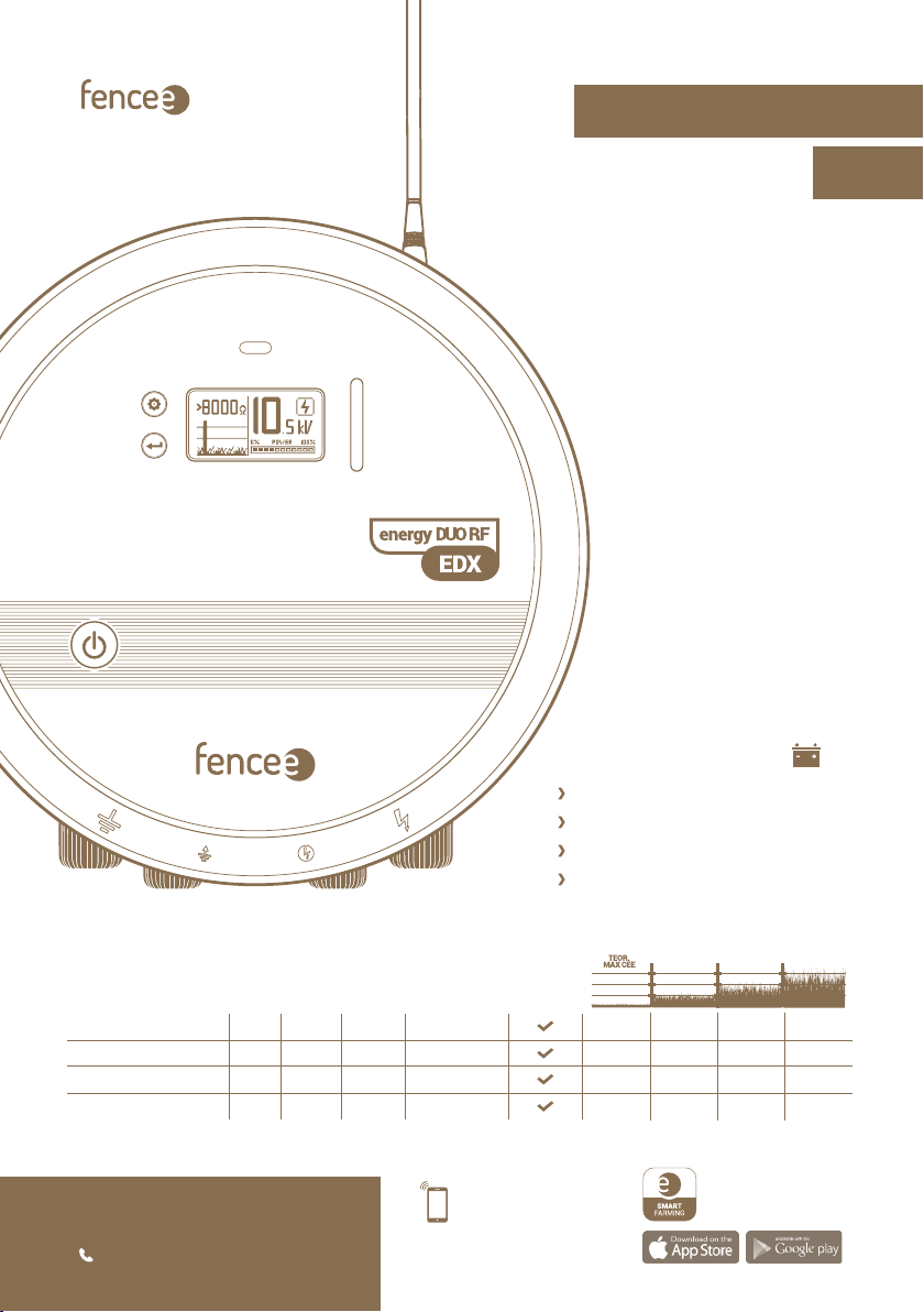
fencee energy DUO RF EDX80
fencee energy DUO RF EDX100
fencee energy DUO RF EDX120
fencee energy DUO RF EDX150
230V ~ /12 V
STORED
ENERGY
OUTPUT
ENERGY
OUTPUT
VOLTAGE
OUTPUT
VOLTAGE 500
SWITCHING
ON / OFF
fencee energy DUO RF EDX80 11 J 8 J 10 000 V 7000 V
fencee energy DUO RF EDX100 13 J 10 J 10 000 V 7000 V
fencee energy DUO RF EDX120 15 J 12 J 10 500 V 7500 V
fencee energy DUO RF EDX150 20 J 15 J 10 500 V 7500 V
230 km 80 km 17 km 8 km
300 km 90 km 22 km 10 km
320 km 100 km 25 km 13 km
350 km 120 km 28 km 16 km
Control and monitor
through mobile application
PHONE
CONTROL
Compatible
•FENCE WiFi GATEWAY GW100
•FENCE GATEWAY GW10
FREE APP
fencee Cloud
Electric fencing
EN
INSTRUCTIONS FOR USE

2
Manufacturer:
VNT electronics s.r.o.
Dvorská 605, 563 01 Lanškroun
Company ID-No.: 64793826
declares that the below listed products:
are in accordance with requirements of standards
and regulations relevant for given type of devices:
Products are safe under condition of their conventional use
in accordance with instructions for use. Declaration
of conformity is issued pursuant to these materials
Issued by accredited Státní zkušebna strojů a.s., Třanovského 622/11,
163 00, Praha 6. This declaration is issued at explicit responsibility
of the manufacturer.
In Lanškroun January 29th, 2021
Ing. Jan Horák
Executive Head of the Company
Phone: +420 730 893 828
info@fencee.eu
www.fencee.eu
DECLARATION OF CONFORMITY
ENERGIZERS FOR ELECTRIC FENCES
fencee energy DUORF EDX80, fencee energy DUO RF EDX100
fencee energy DUORF EDX120, fencee energy DUO RF EDX150
Test Report No.:
39 057
2014/35/EU
2014/30/EU

3
Thank you for purchasing the product
of the company VNT electronics s.r.o.
The equipment conforms to safety regulations in accordance with
valid legislation as well as relevant EU (CE) regulations.
We also ask you to read these instructions for use before using the device carefully
and to keep it for possible application in the future.
Electric fence must be constructed so that persons are protected against
unintentional contact with pulses conductors under normal operating conditions.
From the point of view of legislation, especially the standard 2014/35/EU - 2014/30/EU
(Low Voltage Directive - Electric appliances for domestics and similar purposes – Safety - Part
2-76: Special requirement on energizers for electric fences) relate to the fences.
R&TTE EN300-220 a EN 61000-6-3:2007 + A1:2011
1. CONTENT
1Content . . . . . . . . . . . . . . . . . . . . . . . . . . . . . . . . . . . . . . . . . . . . . . . . . . . . . . . . . . . . . . . . . . . . . . . 3
2Important recommendations . . . . . . . . . . . . . . . . . . . . . . . . . . . . . . . . . . . . . . . . . . . . . . . . . . . . . . . . . . . . 4
3Package contents . . . . . . . . . . . . . . . . . . . . . . . . . . . . . . . . . . . . . . . . . . . . . . . . . . . . . . . . . . . . . . . . . . . . . 4
4Function electric fence . . . . . . . . . . . . . . . . . . . . . . . . . . . . . . . . . . . . . . . . . . . . . . . . . . . . . . 5
5Introduction . . . . . . . . . . . . . . . . . . . . . . . . . . . . . . . . . . . . . . . . . . . . . . . . . . . . . . . . . . . . . . . . . . . . . . . . . . . . . . . 6
5.1 Remote control . . . . . . . . . . . . . . . . . . . . . . . . . . . . . . . . . . . . . . . . . . . . . . . . . . . . . . . . . . . . . 6
5.2 Enerizers EDX with power output higher than 5 J . . . . . . . . . . . . . . . . . . . . . . . . . . . 7
5.3 List of main advantages . . . . . . . . . . . . . . . . . . . . . . . . . . . . . . . . . . . . . . . . . . . . . . . . . . . . . . . . . . . . 8
6Product description . . . . . . . . . . . . . . . . . . . . . . . . . . . . . . . . . . . . . . . . . . . . . . . . . . . . . . . . . . . . . . . . . . . . . . 9
7Ready to use . . . . . . . . . . . . . . . . . . . . . . . . . . . . . . . . . . . . . . . . . . . . . . . . . . . . . . . . . . . . . . . . . . . . . . 10
8Control . . . . . . . . . . . . . . . . . . . . . . . . . . . . . . . . . . . . . . . . . . . . . . . . . . . . . . . . . . . . . . . . . . . . . . 14
9Explanation of LED indicating lights and bargraph indicator . . . . . . . . . . . . . . . . . . . . 15
10 Display . . . . . . . . . . . . . . . . . . . . . . . . . . . . . . . . . . . . . . . . . . . . . . . . . . . . . . . . . . . . . . . . . . . . . . 16
10.1 Basic screen . . . . . . . . . . . . . . . . . . . . . . . . . . . . . . . . . . . . . . . . . . . . . . . . . . . . . . . . . . . . . 16
10.2 Informative screen . . . . . . . . . . . . . . . . . . . . . . . . . . . . . . . . . . . . . . . . . . . . . . . . . . . . . . . . 18
10.3 Setting screen . . . . . . . . . . . . . . . . . . . . . . . . . . . . . . . . . . . . . . . . . . . . . . . . . . . . . . . . 19
11 Safety guidelines . . . . . . . . . . . . . . . . . . . . . . . . . . . . . . . . . . . . . . . . . . . . . . . . . . . . . . . 22
12 Troubleshooting . . . . . . . . . . . . . . . . . . . . . . . . . . . . . . . . . . . . . . . . . . . . . . . . . . . . . . . . . 25
13 Guarantee . . . . . . . . . . . . . . . . . . . . . . . . . . . . . . . . . . . . . . . . . . . . . . . . . . . . . . . . . . . . . . . . . . . . . . . . . . . 26
14 Technical parameters . . . . . . . . . . . . . . . . . . . . . . . . . . . . . . . . . . . . . . . . . . . . . . . . . . . . . . . . . . . . . . . . 27

4
We recommend that this manual is read thoroughly and fully
understood before using the device and that it is retained for
future reference!
2. IMPORTANT RECOMMENDATIONS
• The energizer will provide better protection for your animals and land. Local conditions and
surroundings always aect the device function and for that reason the manufacturer is not
able to guarantee full protection against damage to the fence system.
• Only use the original 14 V/2 A adapter to supply the energizer. The supply voltage must not
exceed 16 V. Controller must be used if the solar panel is used as the energizer must not be
connected directly to the panel.
• Switch o the energizer before carrying out any work on the electric fence system.
• Read thoroughly the Safety Guidelines paragraph.
• Strictly observe all safety guidelines during installation work.
• Do not connect the device on one fence system to another appliance. Damage to all connec-
ted devices and appliances may occur in the event of lightning strike.
• The device may only be repaired by the manufacturer’s qualied personnel.
• Please dispose all waste in accordance with your country’s code of practice.
• Do not let the unconnected battery cable hang freely as the short circuit and the consequent
destruction of the energizer may take place.
• The displayed output voltage tolerance is ±10%.
3. PACKAGE CONTENTS
• Energizer fencee energy DUO RF EDX
• Earthing cable
• Connecting cable to the fence system
• RF antenna
• 14 V/2 A power supply adapter for mains connection
• Battery cable
• fencee warning sign
• 2 installation self-tapping screws and rawlplugs
• User Manual
5
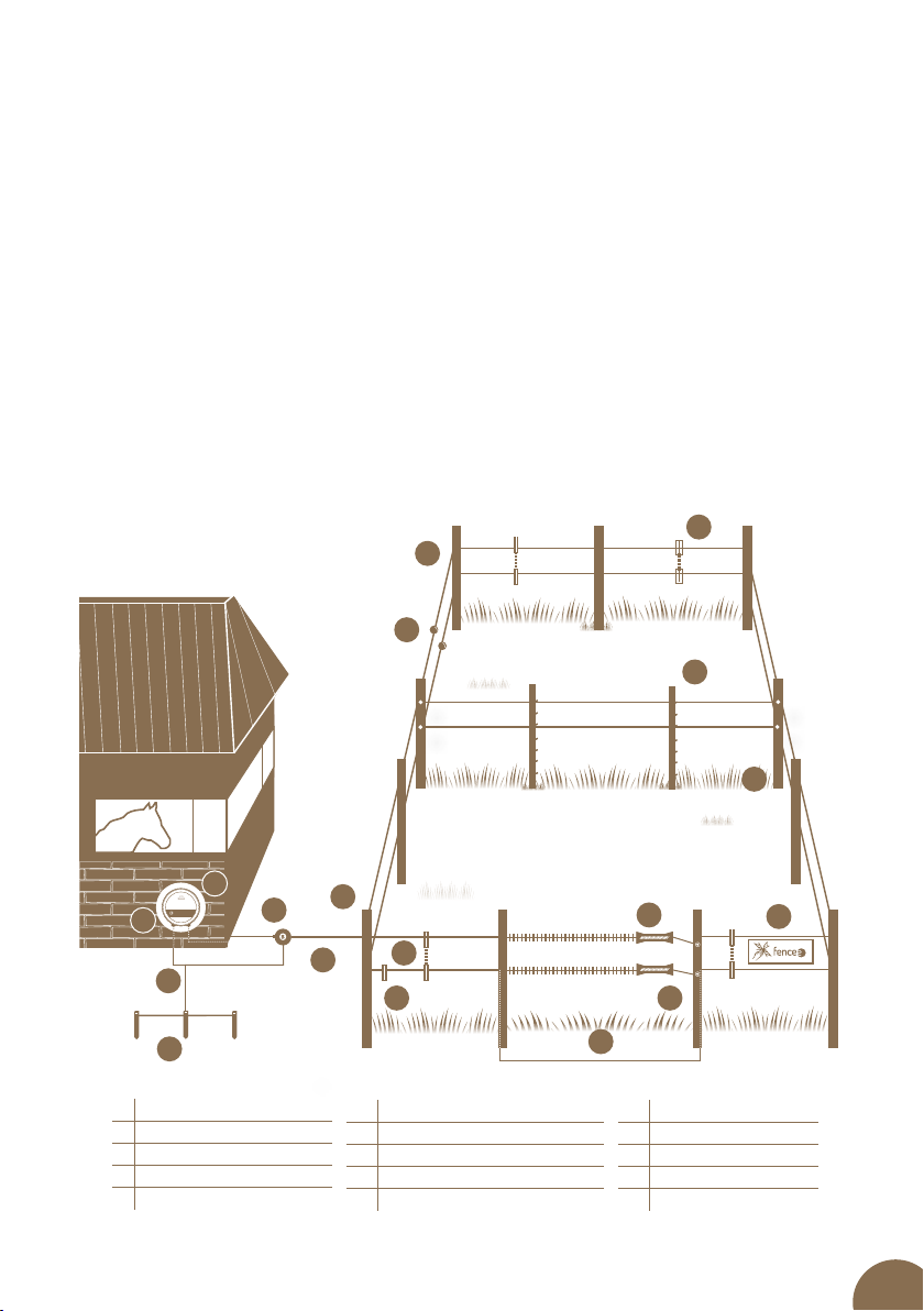
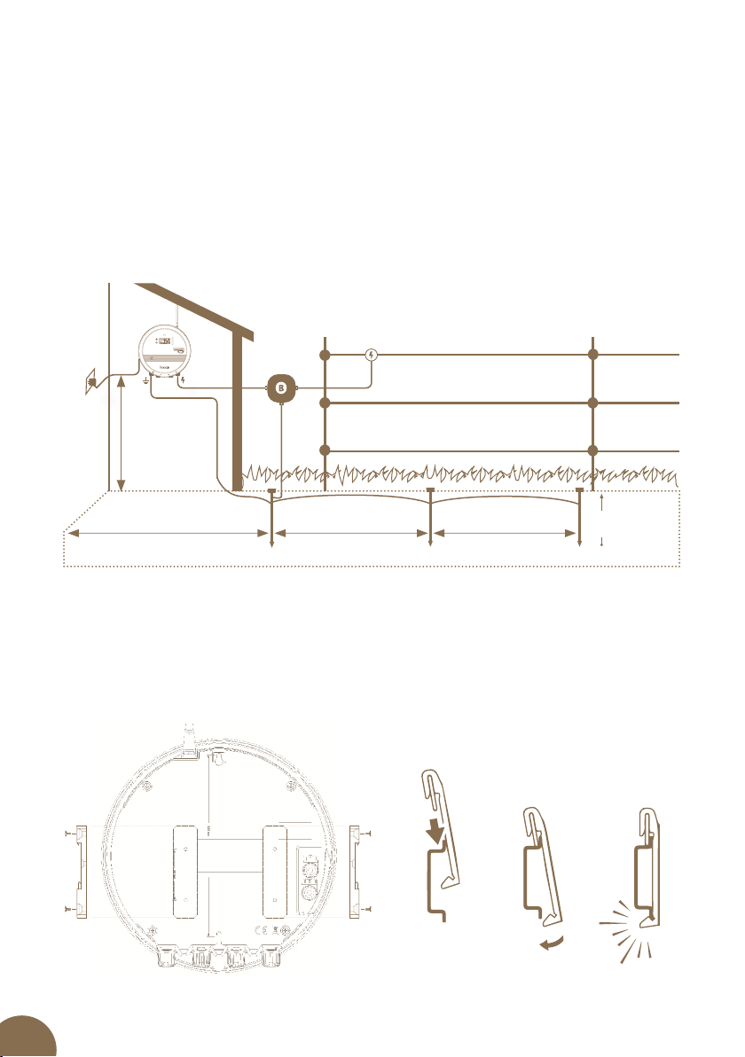
4. FUNCTION ELECTRIC FENCE
How the electric fence works
Electric fence system consist from the energizer and fencing marked with posts and
conductors. The energizer creates regular high-voltage impulses that generate a voltage
between the conducting material and the ground. When an animal (or a person, vegetation
or similar) creates a connection between the ground and the conducting material, the circuit
is completed. Generated impulses are unpleasant, but not dangerous to people or animals as
they only act for a short period of time and results in the desired deterrent eect. The impulse
lasts for a matter of milliseconds. These fences serve not only to enclose an area, but also act
as a deterrent e.g. to protect against wild boars.
Benefits of electric fence systems:
• Electric fences are long-lasting, simple to put up and great value for money compared with
normal fences.
• It is easy to assembly and exible for using.
• Designed for guarding and protecting dierent animals.
• Compared to other fences, such as barbed wire, it does not cause any damage to the animals.
3
9
4
6
2
15
14
12
5
8
10
11
13
6
7
8
11
1
6High-voltage connecting cable
7Conductor
8Line connector
9Fixed post
10 Tensioner
11 Insulators
12 Flexible post
13 Warning sign
14 Gate
15 Insulator of gate
1Energizer
2On/o button on energizer
3Earthing cable
4Anticorrosive earthing rod
5Lightning diverter
6
5. INTRODUCTION
Powerful energizers energy DUO RF EDX are suitable for long and densely overgrown fen-
ce system, where it is essential to ensure maximum eciency and reliability. Owing to their
performance, they are able to overcome even densely overgrown fence systems and provide
required voltage along the entire fence system length. The integrated microprocessor fully
controls the operation and ensures optimal performance taking into account the condition of
the fence system and the current situation.
Energizer energy DUO RF EDX may be either powered from 230 V mains using 14 V power
supply adapter (include in the package contents) or appropriate 12 V battery.
The fence load is continuously measured during the fence system operation. The energizers
energy DUO RF EDX power output is then automatically adjusted to keep the required out-
put voltage in the widest possible load range. This control signicantly aids in saving energy
when using quality fence system with a low load. It also optimises energy consumption to
maintain adequately high fence system voltage, which is, for example, overgrown with grass
(high load).
LED indicator lights and BARGRAPH on the front of the energizer show the power supply sta-
tus and fence system voltage and also signal any potential faults on the fence.
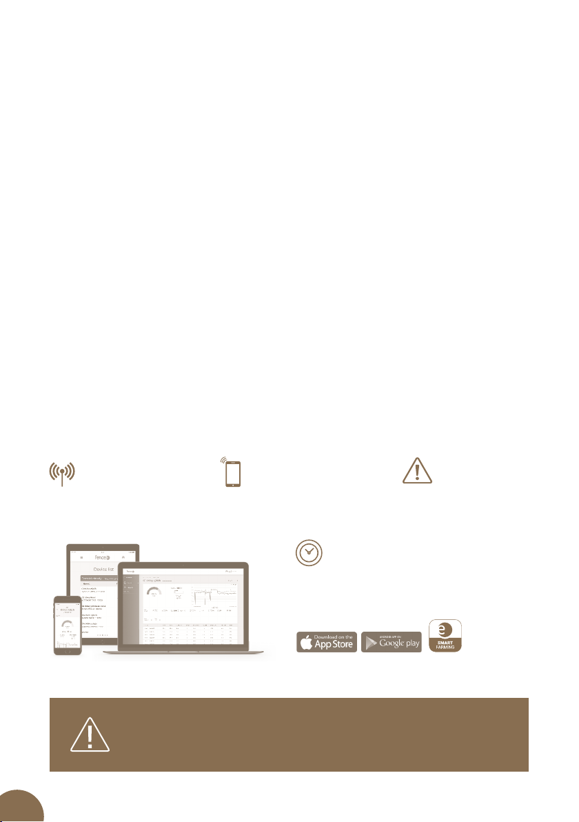
5.1 Remote control
Energizers energy energy DUO RF EDX may be remotely controlled using RF technology and
Cloud application; it is also essential to install FENCE WiFi GATEWAY GW100, which centrally
controls and monitors all connected devices. The EDX energizer is paired with the FENCE WiFi
GATEWAY GW100 thus the energizer may be remotely controlled using the fencee Cloud
application from mobile phone or via web interface.
UPTODATE
INFORMATION
Online up-to-date
information on all devices.
Control and monitor
using mobile application.
CONTROL
FROM PHONE
ALARM
SIGNALLING
Immediate warning sent
to the phone and e-mail
relating to the problem.
SAVING TIME
Using remote control means that walk around
the fence system is no longer required. All is
monitored and controlled from the phone, web
site or gateway.
Free app
fencee Cloud
Energizers fencee energy DUO RF EDX cannot be paired and
controlled by remote control, which is designed only for
energizers fencee power DUO RF PDX.

7
5.2 Energizers energy DUO RF EDX with power output higher than 5 J
Standard’s special requirements must be observed for energizers with power output higher
than 5 J, namely time cut-o limit when the power output is increased and thus ensuring
safety.
Products must be identied by mark.
fencee energizers have time cut-o limit of 50 seconds, which means that whilst the fence
system is under load and its resistance drops below 500 Ohm (overgrown grass, fallen branches,
etc.), the energizer will supply the maximum of 5 J for 50 s. If the fence system resistance does
not increase during this time (carrying out corrective measures), the energizer will gradually
increase the power output (e.g. EDX150 model up to 15 J).
Acoustic and visual warning when the fence system is suddenly under load is another feature.
If the fence resistance drops abruptly during one pulse from over than 1,000 Ohm to less than
400 Ohm (fallen branches, tangled animal or human, etc.), alarm is triggered after six pulses,
acoustic warning and red LED indicator light ashes. At the same time, the pulse period is
shortened to 3 s. The alarm is switched o after increasing the fence resistance to more than
600 Ohm or after the time limit of 10 min. Both functions are independent and separate.
Energizers energy DUO RF EDX may also be remotely controlled from the FENCE GATEWAY
GW10, which cannot be connected to Wi-Fi, consequently you will not be able to control using
mobile phone or via web interface, only from the gateway.

8
5.3 List of main advantages
LED Bargraph
Provides visual information on fence system status
Battery management
Battery status monitoring and management
LCD display
Large graphic LCD display that shows all important information
Reduced power
Yellow output for reduced power output
Control push buttons
Easy and simple operation
Measuring earthing
Green output is used for measuring the quality of earthing
Cloud connection
Using FENCE WiFi GATEWAY GW100
Power switching
Manual switching between the high and low power output; option for reducing
demand on the battery
Up-to-date information
Online up-to-date information on all devices
Control from phone
Control and monitor using the fencee Cloud mobile application
Alarm signalling
Immediate problem alert sent to the phone and e-mail
Combined power supply
Power supply is either from 230 V mains or standard 12 V battery, which may also be
used as the backup power supply
SIM card is not required
No additional equipment operating costs
9
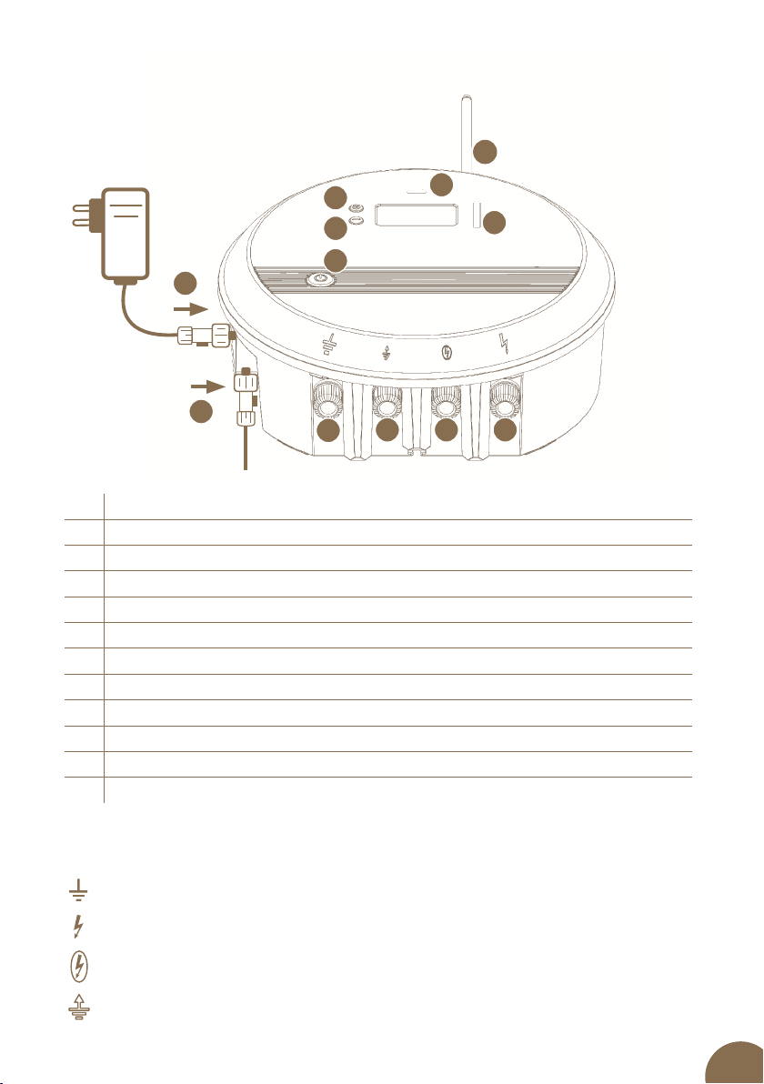
Meaning of displayed symbols
Earthing connection for connecting to your earthing system.
Full voltage fence system connection for connecting to your fence system.
1Waterproof connector for connecting 14 V/2 A adapter
2Waterproof connector for connecting 12 V battery
3SMA connector and RF antenna
4Energizer connection monitoring and status indication shown on LED display
5BARGRAPH shows fence system voltage
6Push button for selecting particular display
7Push button used for conrming / Changing values
8ON/OFF button
9Earthing (black)
10 Connection for measuring the quality of earthing (green)
11 Connection to fence system with reduced power (yellow)
12 Connection to fence system (red)
Reduced power fence system connection.
Connection for measuring the quality of earthing.
4
5
6
7
1
2
910
8
11 12
3
6. PRODUCT DESCRIPTION
10
7. READY TO USE
Choose a place suitable for installation of energizer.
• Where you can achieve a good earthing.
• Which is distant enough from children and animals.
• Where energizer is well accessible.
• Where permanent water stream is avoided.
To mount energizer on wall, use attached screws, on which you can hang the energizer easily.
1. 2. 3.
3m
Energizer min. 20 cm
above the ground
MIN.
1m
3m
Assembly of energizer by using DIN rail
Energizer can be easily and practically mounted by using DIN rail and mounting bracket.
Set for assembly on DIN rail can be ordered as separate accessories.
Min. 10 metres from
next earthing point

11
Earthing
Correct earthing is very important because total function of the fence system is
dependent on it!
Beat earthing rod with corrosion protection into ground completely at place with maximum
and permanent humidity. On dry pieces of land or in case of soils with lower electric
conductivity, use one or several supplementary earthing rods (with length of minimum of
1 m) and place them at distance of approximately 3 metres from each other.
Exceptions are fence system powered by battery energizer or working with low output. Here
minimum length of earthing rod of 50 cm is recommended.
Distance of at least 10 metres must be between earthing rod of fence system and another
earthing system, for example earthing of a house, protective earthing of electric supply
system or earthing of violation alarm.
Do not connect the energizer to already existing earthing.
Antenna installation
Screw the RF antenna onto the SMA connector.
•Energizers must be installed in a dry place.
•Never put energizer on ground – in moist or wet environment.
•Fasten energizer by means of hanging screw or DIN rail with mounting
bracket in vertical position – at least 20 cm above ground.
•Never expose energizer to continuous water stream.
12
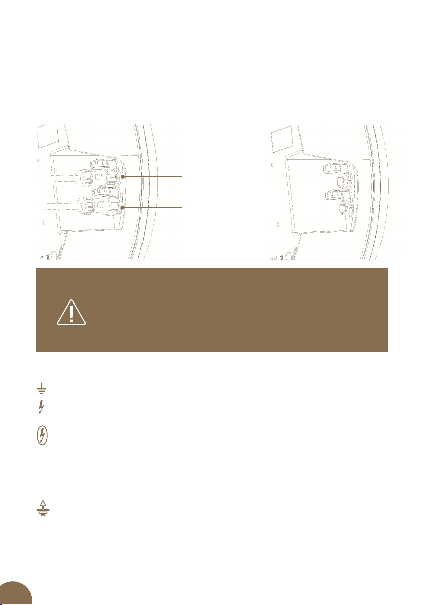
Connecting connectors
Models fencee energy DUO RF EDX have two waterproof input connectors; upper one
for adapter connection and lower one for battery connection. Connectors may be wrongly
connected thus always make sure that the correct connections taken place. This design has
preference for connecting to the mains voltage with the option of connecting to the battery,
as a backup power supply in the event of power failure. Running the energizer for a long time
just from the battery is not desirable due to the higher energy consumption and low capacity
of conventional batteries.
Connecting outputs
Connect the black earthing output to the earthing rod using earthing cable.
Connect the red output to the fence system using the connecting cable.
Yellow output is intended for connecting fence system where we always require reduced
energy in order that animals receive weaker, approximately half strength impulse; this
relates to fence system for younger and smaller animals (foals, calves). It is also connected
separately to the larger fence system lower wire, where vegetation is expected to be dense
with technical measures to prevent losses, namely voltage leakage to the ground as it is
usual in standard connections thus the energizer power output is not reduced. The other
wires connected to the red output are powered separately at full voltage.
Green output is intended for measuring the quality of earthing to nd out whether the
existing earthing is satisfactory or requires upgrading due to the location, e.g. adding
another earthing rod, irrigate it or repair connections. It is always required to install
measuring electrode located 10 m from the energizer earthing point. Use non-corroding
well conducting rod at least 20 cm long for the measuring electrode. Connect high voltage
cable to the green energizer connection.
If one of the connectors is not used then the connector cover
must be screwed in to keep the connector watertight.
If the the adapter and battery are connected to wrong co-
nnectors, charging and the low battery indication will not work
and the battery will not be discharging.
Upper connector
for ADAPTER
Lower connector
for BATTERY
13
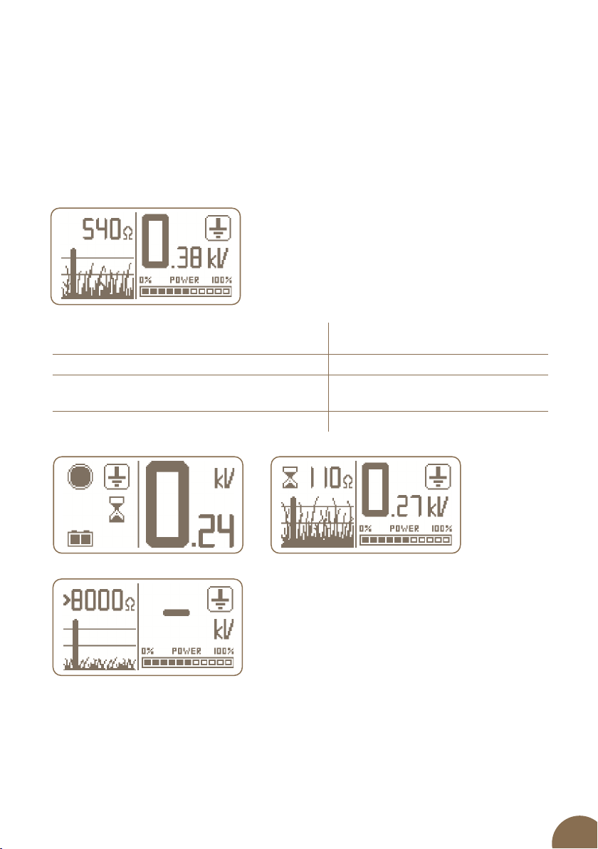
Ground voltage shown on
the energizer display Status
0 to 0,20 kV OK
0,20 to 0,50 kV Check earthing; add another earthing
rod as a precaution
> 0,5 kV Carry out repairs or add earthing rod
If a dash is displayed on the energizer display next to measuring the quality of earthing
symbol it indicates either that the measuring electrode is not connected to the green output
or that the fence system wire is not short-circuited (if fence system impedance is higher than
500 Ohm).
It is also important what fence system impedance the energizer measures. If the energizer
shows impedance of 500 Ohm or lower, i.e. long or overgrown fence system then there is no
need to install anything else and the earthing check works automatically. Check the ground
voltage on the energizer according to the below table.
If the fence system impedance is higher than 500 Ohm, i.e. quality fence not subjected to
load, then it is required to short-circuit the fence system to enable the measurement and thus
determine the quality of earthing. To carry out short-circuiting, the overhead fence system
wire is earthed at a location of at least 50 m from the energizer. Use good quality earthing rod,
hammer it into the ground and connect it to the wire, subsequently check the ground voltage
on the energizer according to the following table.

14
8. CONTROL
ON/OFF AND POWER OUTPUT SWITCHING PUSH BUTTON
As with DUO PD power models, large control push button is used for basic control.
The ON/OFF switch push button has extended functionality, which is used for switching
the energizer power output. After switching o and then switching on again, the energizer
remembers the last set power output.
ENERGIZER IS SWITCHED OFF; BY PRESSING PUSH BUTTON:
Long press (>2s)
Energizer is switched on
Short press
No response
ENERGIZER IS SWITCHED ON; BY PRESSING PUSH BUTTON:
Long press (>2 s) Manual switching between the high and low power
output (approximately 50%). User selectable; when, for example, it is used for
more sensitive animals or to reduce demand on battery, if required. The low power
output is always limited to the maximum of 5 J.
Short press
Energizer is put into the Standby Mode
ENERGIZER IS IN STANDBY MODE; BY PRESSING PUSH BUTTON:
Short press
Energizer is fully switched off
Long press (>2 s) Energizer is switched on
Long press (>5 s) Switches to the Pairing Mode (described in paragraph
relating to Pairing on Page 21)

15
–
–
–
–
LED
BARGRAPH INDICATOR
Indicating statuses are as follows:
LED control:
BURNING / BLINKING
• Blinking Operation on battery only
• Permanent burning – Operation with adapter
COLOR
• Blue Operation at higher output (100%)
• Purple Operation at lower output (c. 50%)
• Red It lights up when battery voltage drops below 12 V.
When battery voltage drops below 11,6 V, warning siren is started (beeping). When battery
voltage drops below 11,4 V, energizer is switched o. Reason is protection of battery from deep
discharge of the battery (battery destruction). If discharged battery and adapter are connected
simultaneously, red LED is burning, until battery is charged at 12 V at least.
BARGRAPH INDICATOR:
To indicate input voltage at fence system, energy DUO RF EDX models are equipped with
BARGRAPH indicator. It consists of six LEDs - 2x RED I2X YELLOW I2X GREEN – ordered
from left to right. BARGRAPH indicator always goes through LEDs from the rst red one up to
indicated position where it stops for a while.
A fast blinking blue indicates the pairing mode of the energizer.
RED YELLOW YELLOW GREEN GREEN
YELLOW YELLOW GREEN GREEN
YELLOW GREEN GREEN
GREEN GREEN
GREEN
RED
RED RED
RED RED YELLOW
RED RED YELLOW YELLOW
RED RED YELLOW YELLOW GREEN
RED RED YELLOW YELLOW GREEN GREEN
9. EXPLANATION OF LED INDICATING LIGHTS AND BARGRAPH INDICATOR
• Voltage < 3 kV - 1x RED
• Voltage 3-5 kV - 2x RED
• Voltage 5-6 kV - 1x YELLOW
• Voltage 6-7 kV - 2x YELLOW
• Voltage 7-8 kV - 1x GREEN
• Voltage > 8 kV - 2x GREEN
RED RED YELLOW YELLOW GREEN GREEN
16
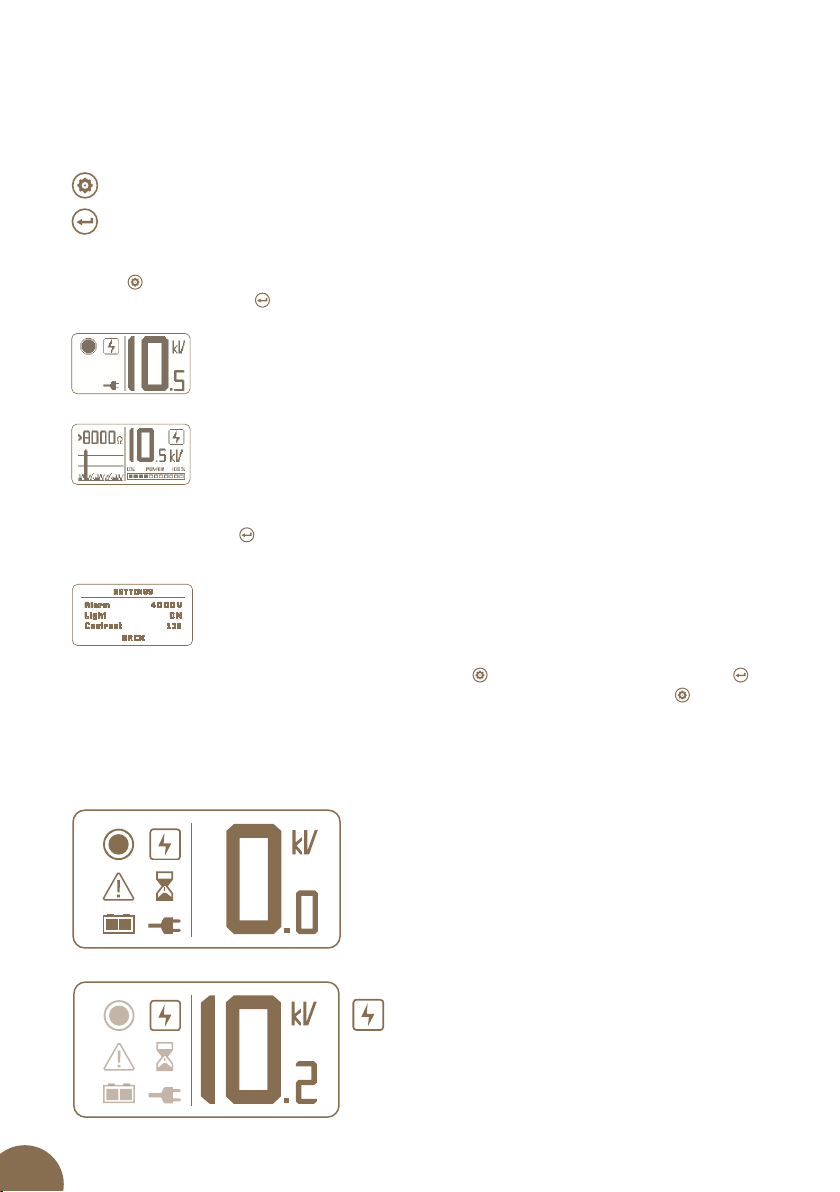
10. DISPLAY
The display shows information on two dierent screens, which can be cycled with the setup
button .
Use the confirm button to change or conrm the parameters on the screen.
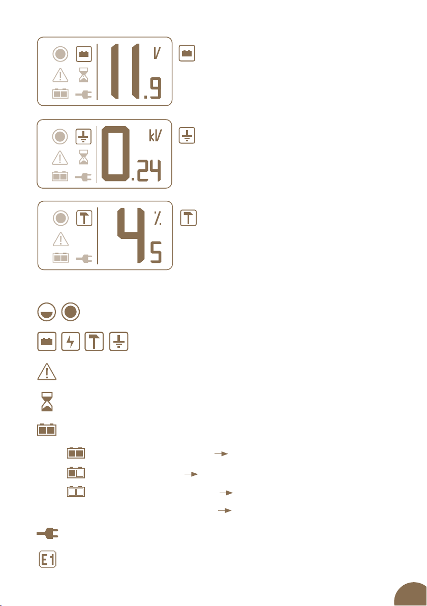
The first basic screen contains a large numeral of the selected parameter
on the right, and icons indicating the energizer status appear on the left.
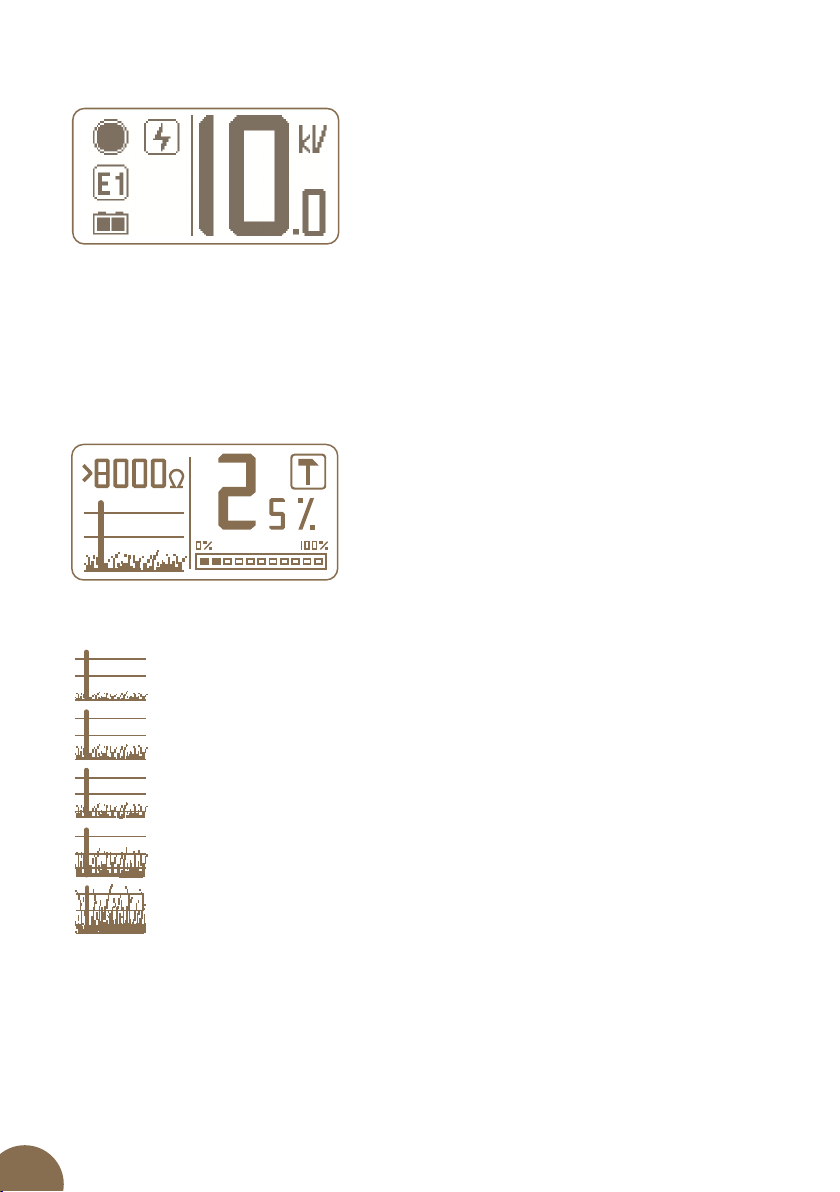
On the second informative screen is displayed the status of the fence on
the left, both numerically (resistance of the fence), but also graphically with
an icon of overgrown grass.
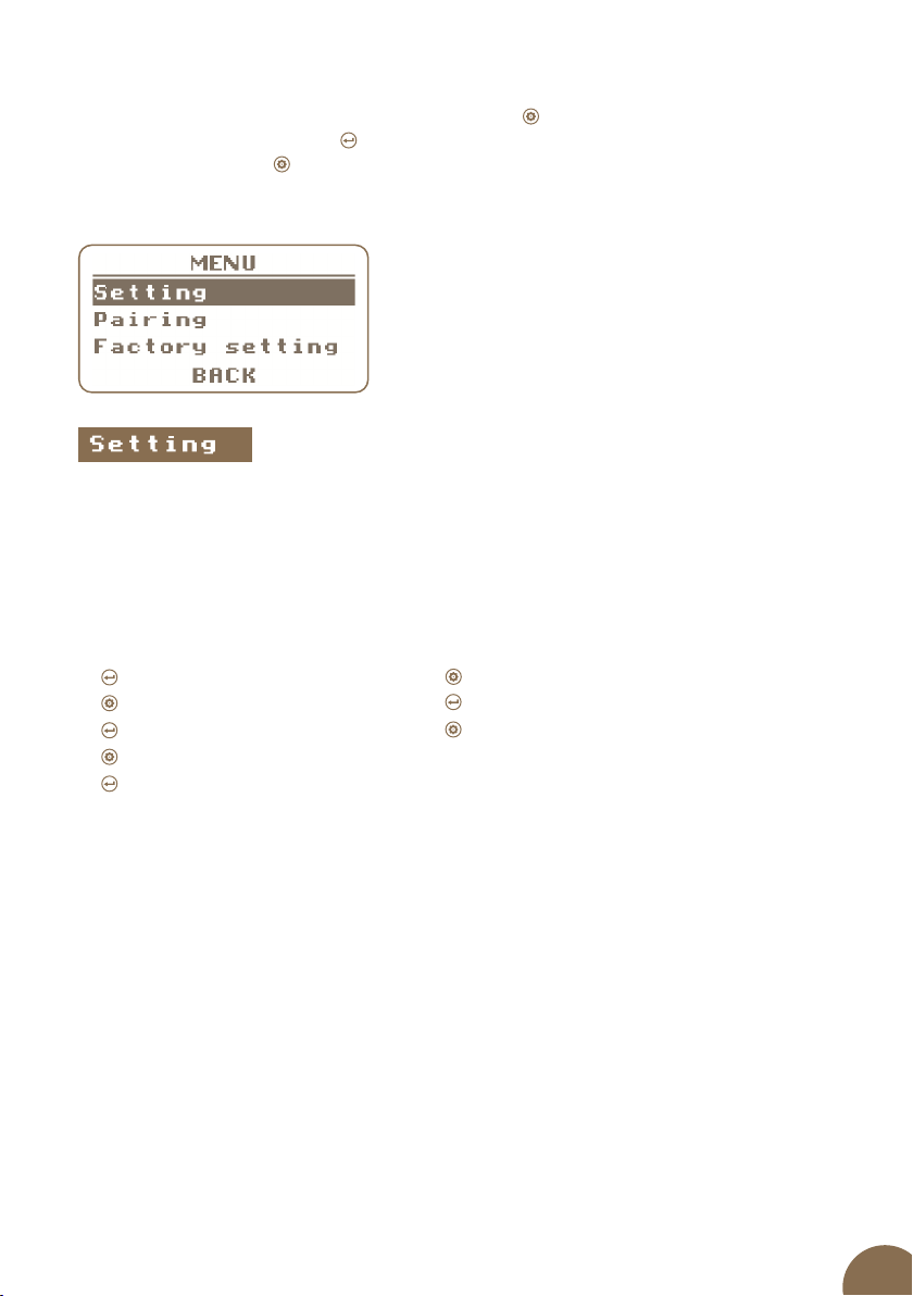
Setting screen
On the rst and second screens, you can select between the displayed parameters using the
confirmation button . There are three options that repeat in a circle - output voltage [kV],
battery voltage [V] and output energy [%].
For entry to setting screen hold for > 2 s Setup button . You can use the confirm button to
access the individual settings between which you move, using the setup button .
Output voltage
In the energy DUO RF EDX models, an information display and two buttons for the control
of this display have been added.
CONFIRM button
SETUP button
10.1 Basic screen
17
Battery voltage
Icons indicating the 50% / 100% mode.
Indicating the displayed parameter.
Triangle indicating a warning.
Hourglass indicates a time delay before ramping up the performance.
Icons on the display:
Output performance – Data indicating the ener-
gizer output needed in the present condition
of the fence, due to its loading and losses.
Measuring earthing
Error message.
Icon indicating the connection of a battery and its status.
Indicates connection to the grid.
Full battery / blue - violet led over 12 V
Half battery / red led 12 – 11,6 V
Empty battery / red led + siren 11,6 – 11,4 V
The energizer will shut down méně než 11,4 V
18
POWERPOWER
10.2 Informative screen
Error message:
Error message E1 - error in evaluation of output voltage - may appear on the basic screen. This
condition indicates that the fence system is not working properly. Energizer´s power is limited
to 5 J and the earthing measuring does not work. This condition can be caused by many die-
rent ones reasons. Therefore, in such a case, it is necessary to send the energizer to our Service
Department for a specialist inspection and repair.
>1000 ohm – a short pen with minimum greenery
1000 ohm – medium pen, with mild growth of vegetation
500 ohm – longer pen, mild growth of greenery
300 ohm – longer pen, medium growth of greenery or mild growth after rain
< 300 ohm – a pen with a dense growth of vegetation, with high power loss
On-screen icons indicating the load on the fence:
19
For entry to setting screen hold for > 2 s Setup button .
You can use the confirm button to access the individual settings between which you move,
using the setup button .
10.3 Setting screen
• Alarm - The voltage setting at which the alarm is triggered can be set in the range of
0 - 8000 V, when 0 kV the voltage alarm is o.
• Light - Setting the backlight time. Here you can set the values of 1 minute, 5 minutes
and continuous light (ON).
• Contrast - Setting the display contrast in the range 90 - 150.
The following items are available:
Back
This serves to leave the settings menu.
Select the BACK item
Conrm your choice
You can toggle among screens
1.
2.
Enter the screen
Select an item
Conrm the selection
Adjust the values
Conrm the values
1.
2.
3.
4.
5.
Entering the screen Leaving the screen
20
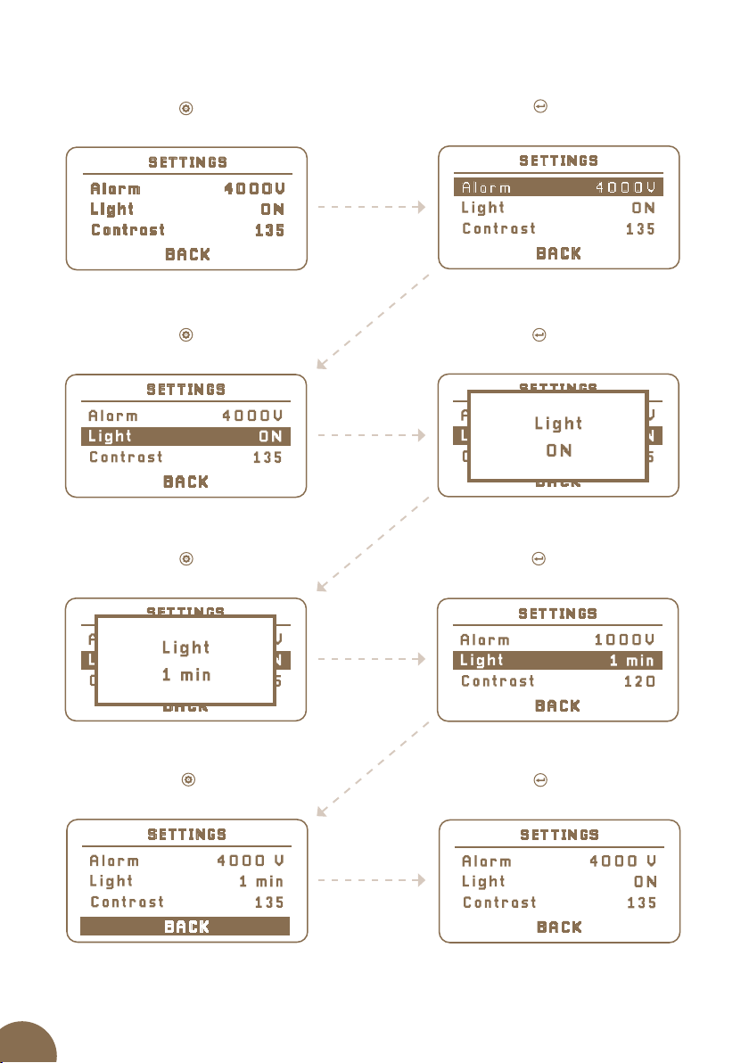
Use the settings button
to go to the back item
The “back” item
Use the enter button to leave
the settings menu
Leaving the settings menu
Example of setting the lighting time at 1 min.
Use the settings button
to enter the settings screen
Settings screen
Use the enter button
to enter the settings
Entering the settings menu
Use the settings button
to select an item
Selection of a required item
Use the enter button
to select adjustment of an item
Adjustment of an item
Changing the value
Use the enter button
to conrm the given value
Changed value
Use the settings button
to change the value
This manual suits for next models
3
Table of contents
Other Fencee Power Supply manuals


