Fencee power DUO PD10 User manual
STORED
ENERGY
OUTPUT
ENERGY
OUTPUT
VOLTAGE
OUTPUT
VOLTAGE 500 Ω
SWITCHING
ON/OFF
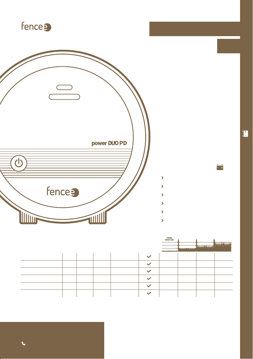
fencee p o w e r DUO P D 10 1,4 J 1 J 9000 V 5000 V
fencee p o w e r DUO P D 20 3 J 2 J 12 000 V 6000 V
fencee p o w e r DUO P D 30 4,5 J 3 J 11 200 V 6400 V
fencee p o w e r DUO P D 40 5,7 J 4 J 10 000 V 5500 V
fencee p o w e r DUO P D 50 7,5 J 5 J 11 000 V 6600 V
fencee p o w e r DUO P D 70 10 J 7 J 10 500 V 7500 V
35 km 8 km 2 km 1,5 km
60 km 15 km 3 km 1,5 km
100 km 23 km 5 km 2 km
120 km 30 km 8 km 3 km
140 km 40 km 10 km 4 km
180 km 70 km 17 km 8 km
fencee p o w e r DUO P D10
fencee p o w e r DUO P D20
fencee p o w e r DUO P D30
fencee p o w e r DUO P D40
fencee p o w e r DUO P D50
fencee p o w e r DUO P D70
230V ~ /12 V
Safe Animal Management | Power supply - 230 V~/ 12 V
Electric fencing
EN
INSTRUCTIONS FOR USE
+420 730 893 828
www.fencee.eu

2
In Lanškroun February 12th. 2018
Ing. Jan Horák
Executive Head of the Company
Phone: +420 730 893 828
info@fencee.eu
www.fencee.eu
DECLARATION OF CONFORMITY
ENERGIZERS FOR ELECTRIC FENCES
fencee power DUO PD10, fencee power DUO PD20
fencee power DUO PD30, fencee power DUO PD40
fencee power DUO PD50
Test Report No.:
37 748
Manufacturer:
VNT electronics s.r.o.
Dvorská 605, 563 01 Lanškroun
Company ID-No.: 64793826
declares that the below listed products:
are in accordance with requirements of standards
and regulations relevant for given type of devices:
Products are safe under condition of their conventional use
in accordance with instructions for use. Declaration
of conformity is issued pursuant to these materials:
Issued by accredited Státní zkušebnou strojů a.s.,
Třanovského 622/11, 163 00, Praha 6.
This declaration is issued at explicit responsibility of the manufacturer.
2014/35/EU
2014/30/EU

3
In Lanškroun August 28th. 2018
Ing. Jan Horák
Executive Head of the Company
Phone: +420 730 893 828
info@fencee.eu
www.fencee.eu
DECLARATION OF CONFORMITY
ENERGIZER FOR ELECTRIC FENCES
fencee power DUO RF PD70
Test Report No.:
37 904
Manufacturer:
VNT electronics s.r.o.
Dvorská 605, 563 01 Lanškroun
Company ID-No.: 64793826
declares that the below listed products:
are in accordance with requirements of standards
and regulations relevant for given type of devices:
Products are safe under condition of their conventional use
in accordance with instructions for use. Declaration
of conformity is issued pursuant to these materials:
Issued by accredited Státní zkušebnou strojů a.s.,
Třanovského 622/11, 163 00, Praha 6.
This declaration is issued at explicit responsibility of the manufacturer.
2014/35/EU
2014/30/EU

4
1. CONTENT
1Content ......................................................................... 4
2Important recommendations .................................................. 5
3Package contents .............................................................. 5
4Function electric fence .......................................................... 6
5Introduction .................................................................... 7
5.1 Enerizers PD with power output higher than 5 J ............................. 7
5.2 List of main advantages ..................................................... 7
6Product description ............................................................. 8
7Ready to use .................................................................... 9
8Control ....................................................................... 12
9Explanation of LED indicating lights and bargraph indicator .................. 12
10 Safety guidelines .............................................................. 13
11 Troubleshooting .............................................................. 16
12 Guarantee ..................................................................... 17
13 Technical parameters ......................................................... 18
Thank you for purchasing the product
of the company VNT electronics s.r.o.
The equipment conforms to safety regulations in accordance with
valid legislation as well as relevant EU (CE) regulations.
We also ask you to read these instructions for use before using the device carefully
and to keep it for possible application in the future.
Electric fence must be constructed so that persons are protected against
unintentional contact with pulses conductors under normal operating conditions.
From the point of view of legislation, especially the standard 2014/35/EU - 2014/30/EU
(Low Voltage Directive - Electric appliances for domestics and similar purposes – Safety - Part
2-76: Special requirement on energizers for electric fences) relate to the fences.

5
3. PACKAGE CONTENTS
•Energizer fencee power DUO PD
•Earthing cable 150 cm
•Connecting cable to the fence system 100 cm
•14 V / 1 A power supply adapter for mains connection
•Battery cable 170 cm
•fencee warning sign – Warning! Electric fence!
•2 installation self-tapping screws and rawlplugs
•User Manual
We recommend that this manual is read thoroughly and fully
understood before using the device and that it is retained for
future reference!
2. IMPORTANT RECOMMENDATIONS
•The energizer will provide better protection for your animals and land. Local conditions and
surroundings always aect the device function and for that reason the manufacturer is not
able to guarantee full protection against damage to the fence system.
•Use only the original adapter to supply the energizer – 14 V / 1 A. The supply voltage must
not exceed 16 V. 12 V controller must be used if the solar panel is used as the energizer must
not be connected directly to the panel.
•Switch o the energizer before carrying out any work on the electric fence system.
•Read thoroughly the Safety Guidelines paragraph.
•Strictly observe all safety guidelines during installation work.
•Do not connect the device on one fence system to another appliance. Damage to all connec-
ted devices and appliances may occur in the event of lightning strike.
•The device may only be repaired by the manufacturer’s qualied personnel.
•Please dispose all waste in accordance with your country’s code of practice.
•Do not let the unconnected battery cable hang freely as the short circuit and the consequent
destruction of the energizer may take place.

6
4. FUNCTION ELECTRIC FENCE
How the electric fence works
Electric fence system consist from the energizer and fencing marked with posts and conductors.
The energizer creates regular high-voltage impulses that generate a voltage between the con-
ducting material and the ground. When an animal (or a person, vegetation or similar) creates
a connection between the ground and the conducting material, the circuit is completed.
Generated impulses are unpleasant, but not dangerous to people or animals as they only
act for a short period of time and results in the desired deterrent eect. The impulse lasts for
a matter of milliseconds. These fences serve not only to enclose an area, but also act as a dete-
rrent e.g. to protect against wild boars.
Benefits of electric fence systems:
•Electric fences are long-lasting, simple to put up and great value for money compared with
normal fences.
•It is easy to assembly and exible for using
•Designed for guarding and protecting dierent animals.
•Compared to other fences, such as barbed wire, it does not cause any damage to the animals.
6High-voltage connecting cable
7Conductor
8Line connector
9Fixed post
10 Tensioner
11 Insulators
12 Flexible post
13 Warning sign
14 Gate
15 Insulator of gate
1Energizer
2ON/OFF button on energizer
3Earthing cable
4Anticorrosive earthing rod
5Lightning diverter
3
9
4
6
2
15
14
12
5
8
10
11
13
6
7
8
11
1

7
5. INTRODUCTION
Energizers power DUO PD may be either powered from 230 V mains using 14 V power supply
adapter (include in the package contents) or appropriate 12 V battery.
The integrated microprocessor fully controls the operation and ensures optimal performance
taking into account the condition of the fence system and the current situation.
The fence load is continuously measured during the fence systems operation. The energizers
power output is then automatically adjusted to keep the required output voltage in the widest
possible load range. This control signicantly aids in saving energy when using quality fence
system with a low load. It also optimises energy consumption to maintain adequately high
fence system voltage, which is, for example, overgrown with grass (high load).
LED indicator lights and BARGRAF on the front of the energizer show the power supply status
and fence system voltage and also signal any potential faults on the fence.
Special transformer ST
extra high voltage with long term protection
Smart Control technology ensures
microprocessor-controlled operation and optimal performance
3 years warranty
Czech product
5.2 List of main advantages
5.1 Energizers PD with power output higher than 5 J
Standard’s special requirements must be observed for energizers with power output higher
than 5 J, namely time cut-o limit when the power output is increased and thus ensuring
safety.
Products must be identied by mark.
fencee energizers have time cut-o limit of 50 seconds, which means that whilst the fence
system is under load and its resistance drops below 500 Ohm (overgrown grass, fallen branches,
etc.), the energizer will supply the maximum of 5 J for 50 s. If the fence system resistance does
not increase during this time (carrying out corrective measures), the energizer will gradually
increase the power output.
Acoustic and visual warning when the fence system is suddenly under load is another feature.
If the fence resistance drops abruptly during one pulse from over than 1,000 Ohm to less than
400 Ohm (fallen branches, tangled animal or human, etc.), alarm is triggered after six pulses,
acoustic warning and red LED indicator light ashes. At the same time, the pulse period is
shortened to 3 s. The alarm is switched o after increasing the fence resistance to more than
600 Ohm or after the time limit of 10 min. Both functions are independent and separate.
8
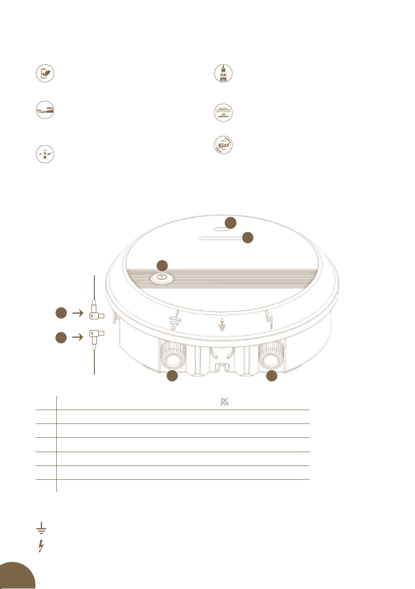
1Connector for connecting adapter ( 14 V /1 A)
2Connector for connecting battery (12 V)
3LED control of connecting energizer and status indication
4BARGRAPH Indicator – indication of voltage on fence system
5ON/OFF switch button
6Earthing (black)
7Connection to fence system (red)
6. PRODUCT DESCRIPTION
3
4
5
67
1
2
Combined models power DUO PD:
Combined power supply
Power supply is either from 230 V mains or
standard 12 V battery, which may also be
used as the backup power supply.
Time delay 50 s
Increase power to maximum power for
safety reasons.
LED Bargraph
Provides visual information on fence
system status.
Battery management
Battery status monitoring and management.
Award Zlatý Klas 2018
energizer power DUO PD50
Power switching
Manual switching between the high and
low power output; option for reducing
demand on the battery.
Meaning of displayed symbols
Earthing connection for connecting to your earthing system.
Full voltage fence system connection for connecting to your fence system.

9
3m
Energizer min. 20 cm
above the ground
MIN.
1m
Min. 10 metres from
next earthing point 3m
1. 2. 3.
Assembly of energizer by using DIN rail
Energizer can be easily and practically mounted by using DIN rail and mounting bracket.
Set for assembly on DIN rail can be ordered as separate accessories.
7. READY TO USE
Choose a place suitable for installation of energizer:
•Where you can achieve a good earthing.
•Which is distant enough from children and animals
•Where energizer is well accessible.
•Where permanent water stream is avoided.
To mount energizer on wall, use attached screws, on which you can hang the energizer easily.

10
Earthing
Correct earthing is very important because total function of the fence system is depen-
dent on it!
Beat earthing rod with corrosion protection into ground completely at place with maximum
and permanent humidity. On dry pieces of land or in case of soils with lower electric condu-
ctivity, use one or several supplementary earthing rods (with length of minimum of 1 m) and
place them at distance of approximately 3 metres from each other.
Exceptions are fence system powered by battery energizer or working with low output. Here
minimum length of earthing rod of 50 cm is recommended.
Distance of at least 10 metres must be between earthing rod of fence system and another
earthing system, for example earthing of a house, protective earthing of electric supply system
or earthing of violation alarm.
Do not connect the energizer to already existing earthing.
• Energizers must be installed in a dry place.
• Never put energizer on ground – in moist or wet environment.
• Fasten energizer by means of hanging screw or DIN rail with mounting
bracket in vertical position – at least 20 cm above ground.
• Never expose energizer to continuous water stream.
ON THE GROUND – IN A PUDDLE ON THE GROUND – UPSIDE DOWN
NEGATIVE
ANGLE
NEVER EXPOSE TO
A CONTINUOUS
STREAM OF WATER!
VERTICAL ON THE
WALL IDEALLY
WITH A CANOPY
We recommend
mounting on DIN rail
80 mm (Art.Nr. 8043)

11
Connecting connectors
Models fencee power DUO PD have two waterproof input connectors; upper one for adapter
connection and lower one for battery connection. Connectors may be wrongly connected
thus always make sure that the correct connections taken place. This design has preference
for connecting to the mains voltage with the option of connecting to the battery, as a backup
power supply in the event of power failure. Running the energizer for a long time just from
the battery is not desirable due to the higher energy consumption and low capacity of
conventional batteries.
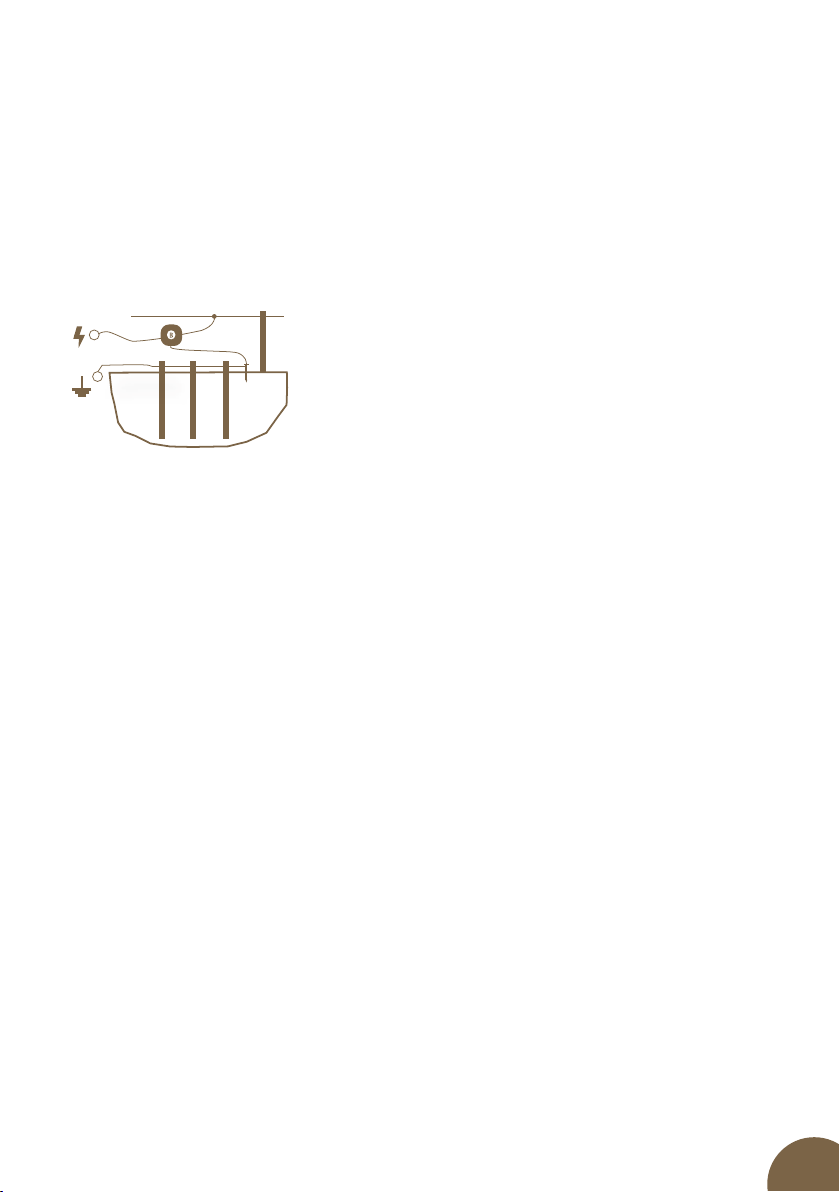
Connecting output terminals
Connect the black earthing output to the earthing rod using earthing cable.
Connect the red output to the fence system using the connecting cable.
If the adapter and battery are connected to wrong connectors,
charging and the low battery indication will not work and the
battery will not be discharging.
Preview of connector wiring.
Positive polarity
14 V / 1 A
Upper connector
for ADAPTER
Lower connector
for BATTERY

12
8. CONTROL
IN SWITCHEDOFF CONDITION OF THE ENERGIZER
Compared to POWER models, the ON/OFF switch button has extended functionality here. Af-
ter rst switch-on of energizer, blue LED is burning or blinking indicating operation at higher
output. After each other switch-on, the energizer remembers selected mode.
IN SWITCHEDOFF CONDITION OF THE ENERGIZER
Long press (>2 s)
Energizer is switched on.
Short press No response.
ENERGIZER IS SWITCHED ON; BY PRESSING PUSH BUTTON:
Long press (>2 s)
Manual switching between the high and low power out-
put (approximately 50 %).
User selectable; when, for example, it is used for more
sensitive animals or to reduce demand on battery, if required. The low power output is
always limited to the maximum of 5 J.
Short press Energizer is fully switched off.
9. EXPLANATION OF LED INDICATING LIGHTS AND BARGRAPH INDICATOR
LED control:
BURNING / BLINKING
•blinking operation on battery only
•permanent burning – operation with adapter
COLOR
•blue operation at higher output (100%)
•purple operation at lower output (c. 50%)
•red it lights up when battery voltage drops below 12 V.
When battery voltage drops below 11,6 V, warning siren is started (beeping). When battery
voltage drops below 11,4 V, energizer is switched o. Reason is protection of battery from
deep discharge of the battery (battery destruction). If discharged battery and adapter are
connected simultaneously, red LED is burning, until battery is charged at 12 V at least.
BARGRAPH INDICATOR:
To indicate input voltage at fence system, power DUO PD models are equipped with
BARGRAPH indicator. It consists of six LEDs - 2× RED I2×YELLOW I2×GREEN – ordered
from left to right. BARGRAPH indicator always goes through LEDs from the rst red one up to
indicated position where it stops for a while.
–
–
–
–

13
Indicating statuses are as follows:
RED YELLOW YELLOW GREEN GREEN
YELLOW YELLOW GREEN GREEN
YELLOW GREEN GREEN
GREEN GREEN
GREEN
RED
RED RED
RED RED YELLOW
RED RED YELLOW YELLOW
RED RED YELLOW YELLOW GREEN
RED RED YELLOW YELLOW GREEN GREEN
•voltage < 3 kV - 1×RED
•voltage 3–5 kV - 2×RED
•voltage 5–6 kV - 1×YELLOW
•voltage 6–7 kV - 2×YELLOW
•voltage 7–8 kV - 1×GREEN
•voltage > 8 kV - 2×GREEN
LED
BARGRAPH INDICATOR
RED RED YELLOW YELLOW GREEN GREEN
10. SAFETY GUIDELINES
Install and operate the electric fence systems in such a way that they do not pose the risk of
electric shock to humans, animals or disturb the environment.
Avoid using the electric fence systems that could trap animals or people.
One electric fence system must not be powered by two or more energizers or by independent
power supply devices designated for electric fence systems of the same equipment.
When operating two or more dierent electric fence systems and if they are powered by
dierent energizers, the minimum distance between the electric fences must be 2,5m. Use
electrically non-conductive material if this distance is required to be smaller.
Do not use barbed or razor wire or any other types of sharp-edged wire to install the electric
fence system.
Non-conductive additional fencing in which barbed or razor wire is used must be at least
150mm from the electric fence system wire and must be earthed at regular intervals.
All electric fence system sections installed along the public roads must be marked with
warning signs attached to poles or fences at regular intervals and visible from the road.

14
Power supply and connecting cables
•Cables that are rated for voltages higher than 1 kV and are located in buildings must be
eectively insulated from the building’s earthing features. This may be achieved by using
insulated high-voltage cables or by leaving appropriate distance between the cable and the
building frame. Do not use standard electrical cables
•Cables that are laid in the ground (soil) must be protected by solid insulator pipes or use
insulated high-voltage cables designed for this purpose. Make sure that the cables will
not be damaged by, for example animal hooves or tractor wheels, which can sink into the
ground. Do not use standard electrical cables.
•Cables must not be placed in pipes together with other circuit, communication or data cables.
Supply and connecting leads and electric line of fence system:
•Shall not cross above overhead power or communication lines. Crossings with overhead
power lines shall be avoided wherever possible. If such a crossing cannot be avoided it shall
be made underneath the power line and as nearly as possible at right angles to it.
•If are installed near an overhead power line, the clearances shall not be less than those shown.
•If are installed near an overhead power line, their height above the ground shall not exceed
3 m. This height applies to either side of the orthogonal projection of the outer most condu-
ctors of the power line on the ground surface, for a distance of:
• 2 m for power lines operating at a nominal voltage not exceeding 1000 V
• 15 m for power lines operating at a nominal voltage exceeding 1000 V
•Being nearby telephone line or telephone cable, must be conducted at a distance of mini-
mum of 2 metres.
Electric animal fences intended for deterring birds household pet containment or training
animals such as cows need only be supplied from low output energizers to obtain satisfactory
and safe performance.
In electrical animal fences intended for deterring birds from roosting on buildings no fence
wire shall be grounded if the fence wires are not connected to metal parts. If one wire is
connected with a metal part (ie a gutter) or a metal structure of the building these metal parts
must be grounded. A warning sign shall be tted to every point where persons may gain ready
access to the conductors.
Where an electric animal fence crosses a public pathway, a non-electried gate shall be
incorporated in the electric animal fence at that point or a crossing by means of stiles shall be
provided. At any such crossing, the adjacent electried wires shall carry warning signs.
Power line voltage Clearance
≤ 1000 V 3 metres
> 1000 ≤ 33000 V 4 metres
> 33000 V 8 metres
Warning sign
•It is of yellow colour with minimum dimensions of 100 × 200 mm
•It is either standard warning sign or contains the following
Inscription on both sides: ˝WARNING! ELECTRIC FENCE˝
•Letters must be at least 25 mm high and indelible
•One warning sign is included in the package contents
15
Overvoltage protective equipment – lightning diverter
To prevent from damages caused by lightning, we recommend leading a circuit of fence sys-
tem near to building via overvoltage protective equipment – lightning diverter fastened to
outer masonry of the building by means of non-combustible materials before its connec-
ting to energizer. This applied also for combined energizers, if they are used together with
a network adapter.
Overvoltage caused by storm can cause insulation of
electric fence system. In such a case, network voltage
can get into electric fence system, and serious danger to
people or animals can occur.
Avoid direct contact with fencing, especially with head, neck or upper part of body. Do not
creep through the fencing or over it. For passing the fence system, use a gate or another point
in installation designed for this purpose.
Generally, we recommend connecting network powered electric fence system only to such
supply networks that are protected with earth-leakage circuit breaker with maximum actua-
ting current of 30 mA. In addition to that, correct installation of energizer with auxiliary dis-
charger and choking coil is necessary, as described within these instructions. It is suitable to
disconnect network supplied electric fence system from network as well as from fencing (if
possible) during storm.
If a network with earth-leakage circuit-breaker was not used for purposes of supplying ener-
gizer, and the enrgizer was connected to the fence system or the network during storm, it
is necessary to check and test it before putting it into operation again. For this purpose, co-
nnection to network with earth-leakage circuit-breaker must be available. For purposes of
testing, connect earthing output of energizer to protective conductor of the supply network
and connect pin to power socket protected with earth-leakage circuit-breaker then. If ener-
gizer beats correctly and does not show any deviations from normal operation subsequently,
it can be connected to fence system again. If the earth-leakage circuit-breaker however falls
out when energizer is connected, you must not use it and it must be repaired professionally
If connecting lines of this energizer are damaged, they must be replaced by manufacturer or
authorized service or another qualied person so that possibility of danger is excluded. Servi-
ce and repairs of these energizers must be performed by authorized persons only! Each user
of electric fence system is responsible for its operation and should perform regular checks of
energizer and fence system at least once a day, depending on operating conditions!
Procedure of checking:
• Visual control of energizer and fence system
• Measuring of minimum voltage of 2500 V in every place of the fence system
If installation is performed inside a building, energizer may not be operated in a room with
increased risk of re in any case (barn, shed, cattle shed). In addition to that, no combustible
materials may be stored near to fence system and connectors of energizer. Installation of ener-
gizer must be made on a re-resistant surface.
For stable using, use only energizers designed for that purpose!

16
11. TROUBLESHOOTING
In case that electric fence system does not give pulse or voltage is lower than 3 kV and red
diode is blinking on BARGRAPH indicator, it is necessary to check below listed causes
Cause Fault removal
Energizer does not work? Disconnect the device from the fence system and switch
it on again! If blue or violet LED is burning and yellow
or green LED is ashing on BARGRAPH indicator, then
the device works properly. Otherwise, the device is
damaged (contact your salesman). When using battery
and accumulator devices, observe correct wiring of poles.
Red LED light is blinking Battery voltage decreased below 12V - replace the battery
with a suciently charged one or connect adapter.
Red LED light is blinking and warning siren
sounds (beeping)
Battery voltage decreased below 11,6 V - replace the
battery with a suciently charged one or connect adapter.
No LED signal is burning Energizer is switched o manually or battery voltage
decreased below 11,4 V and energizer was switched o
automatically. Reason is protection of battery from its
deep discharge (and battery destruction). Replace the
battery with a suciently charged one or connect adapter
– until battery voltage reaches at least 12 V, red LED will
be burning.
Lead-in or short circuit of supply lines of the
fence system
Do not use conventional cables for supply lines. High-
voltage cable is recommended.
Conductor has adverse properties (thin
diameter, high resistance)
Use high-quality conductor with low resistance and
larger diameter. Ensure high-quality correct connection
of conductors.
Low-quality earthing, too short earth rod,
corrosion, dry soil
Add next rod, moisten.
Lead-in via growth near fence system Remove the growth (mow it).
Conductor on ground (for example break,
insufficient mechanical tension)
Repair fencing, use special connectors, stretch conductor.
Too long fence system. Was correct
accessories used for given purpose?
Use accessories suitable for given length of fence system
and for animals – in case of need, consult specialized
salesman.
Insulator pierces, losses occur Replace defective and weather-worn insulators.
Conductor is connected via knot, insufficient
connection
Use relevant special connectors for the conductor.
Do not connect battery or accumulator energizers to electric power network or devices being
connected to network voltage, except for sources determined to that by the manufacturer, in
any case.This energizer may not be used by persons (including children) who have limited physi-
cal, perceptive or mental abilities or do not possess sucient experiences and knowledge, when
they are not under supervision or are not trained for operating energizer by persons who are
responsible for their safety. Children should be under supervision so that there is not chance that
they play with the energizer.
Ensure that all connected network supplied auxiliary circuits have at least the same protection
class as energizer.

17
12. GUARANTEE
In addition to a guarantee requested by law, we provide you with a guarantee in accordance with
below listed conditions:
•Guarantee period begins on the day of its purchase. Guarantee claims are acknowledged
explicitly pursuant to submission of bill or cash voucher. Guarantee repair is free of charge,
or we reserve the right to deliver a device of the same value.
•Guarantee is valid in case of correct use in accordance with the instructions for use. It expires
in case of interferences by unauthorized persons and in case of using spare parts of foreign
origin.
•All deciencies resulting from material defects or manufacturing defects shall be removed in
manufacturer´s discretion by repairing or free-of-charge replacement of the energizer.
•In case of delivering spare parts or repairing, original guarantee period is not prolonged.
•Guarantee period and address of guarantee provider can be found in attached instructions
for use of given type of energizer.
•Accumulators or batteries of any type, damages due to overvoltage (caused by lightning
among others) and damages due to spill-over of accumulator acid are not included in the
guarantee.
This energizer is provided with guarantee period of 3 years according to our conditions
for guarantee! Safety instructions, earthing, putting into operation, care of batteries
and accumulator, conditions for guarantee and possible fault sources can be found in
attached instructions for use!

18
pow er DUO PD1 0 pow er DUO PD2 0 pow er DUO PD3 0
POWER SUPPLY
POWER CONSUMPTION
230 V ~
3 W
12 V
40–100 mA
230 V ~
5 W
12 V
40–140 mA
230 V ~
5 W
12 V
80–240 mA
INPUT ENERGY 1,4 J 3 J 4,5 J
OUTPUT ENERGY 1 J 2 J 3 J
OUTPUT VOLTAGE 9000 V 12 000 V 11 200 V
OUTPUT VOLTAGE 500 Ω 5000 V 6000 V 6400 V
ON/OFF
LED ON/OFF
LED IMPULS
LED LOW BATTERY VOLTAGE
LED POWER LOWER 50%
LED ERROR CHECK
LED IMPULS BARGRAF
TEOR. MAX CEE 35 km 60 km 100 km
LOW VEGETATION 8 km 15 km 23 km
MEDIUM VEGETATION 2 km 3 km 5 km
HIGH VEGETATION 1,5 km 1,5 km 2 km
GROUNDING 1 m 1× 2× 2×
EL. FENCE NETTING 3× 5× 6×
WEIGHT 1512 g 1534 g 1540 g
DIAMETER 210 mm
DEPTH 66 mm
13. TECHNICAL PARAMETERS

19
pow er DUO PD4 0 pow er DUO PD5 0 pow er DUO PD7 0
POWER SUPPLY
POWER CONSUMPTION
230 V ~
9 W
12 V
80–320 mA
230 V ~
9 W
12 V
100–420 mA
230 V ~
12 W
12 V
300–750 mA
INPUT ENERGY 5,7 J 7,5 J 10 J
OUTPUT ENERGY 4 J 5 J 7 J
OUTPUT VOLTAGE 10 000 V 11 000 V 10 500 V
OUTPUT VOLTAGE 500 Ω 5500 V 6600 V 7500 V
ON/OFF
LED ON/OFF
LED IMPULS
LED LOW BATTERY VOLTAGE
LED POWER LOWER 50%
LED ERROR CHECK
LED IMPULS BARGRAF
TEOR. MAX CEE 120 km 140 km 180 km
LOW VEGETATION 30 km 40 km 70 km
MEDIUM VEGETATION 8 km 10 km 17 km
HIGH VEGETATION 3 km 4 km 8 km
GROUNDING 1 m 3× 3× 3×
EL. FENCE NETTING 6× 8× 14×
WEIGHT 1540 g 1557 g 1659 g
DIAMETER 210 mm
DEPTH 66 mm

23062023
VNT electronics s.r.o.
Dvorská 605, 563 01 Lanškroun
Czech Republic
info@fencee.eu
+420 730 893 828
Customer Service: +420 730 893 827
fencee.cz fenceeczech
Electric fencing
www.fencee.eu
www.fenceefarm.com
Stamp and signature of seller:
This manual suits for next models
5
Table of contents
Other Fencee Power Supply manuals


Popular Power Supply manuals by other brands


Phoenix Contact
Phoenix Contact QUINT-PS-100-240AC/24DC/2.5 manual

Altronix
Altronix AL125220 Series installation guide

Tactical Power Products
Tactical Power Products 13.5Vdc 10A Power Series installation manual

Manson Engineering Industrial
Manson Engineering Industrial NEP-8323 quick start guide

Altronix
Altronix Tango1B installation guide

Chroma
Chroma 63610-80-20 Operation & programming manual