EPS PSB 10000 4U User manual
EPSEPS
StromversorgungStromversorgung
Operating Guide
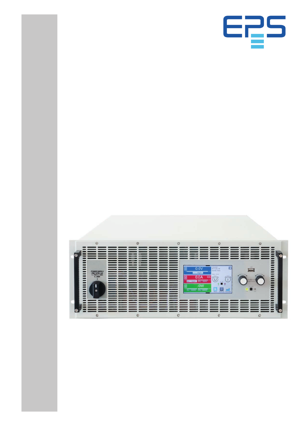
PSB 10000 4U
Bidirectional DC Power Supply

© EPS Stromversorgung in 2022, this information is subject to change without notice 230000800_manual_psb_10000_4u_30kw_en_04
TABLE OF CONTENTS
1. General
1.1 About this document 5
1.1.1 Retention and use 5
1.1.2 Copyright 5
1.1.3 Validity 5
1.1.4 Symbols and warnings in this document 5
1.2 Warranty 5
1.3 Limitation of liability 5
1.4 Disposal of equipment 6
1.5 Product key 6
1.6 Intended usage 7
1.6.1 Symbols and warnings on the device 7
1.7 Safety 8
1.7.1 Safety notices 8
1.7.2 Responsibility of the operator 9
1.7.3 Requirements to the user 9
1.7.4 Responsibility of the user 9
1.7.5 Alarm signals 10
1.7.6 Functionality test 10
1.8 Technical Data 11
1.8.1 Approved operating conditions 11
1.8.2 General technical data 11
1.8.3 Specific technical data 12
1.8.4 Views 16
1.8.5 Control elements 21
1.9 Construction and function 22
1.9.1 General description 22
1.9.2 Block diagram 22
1.9.3 Scope of delivery 23
1.9.4 Accessories 23
1.9.5 Options 23
1.9.6 The control panel (HMI) 24
1.9.7 USB port (rear side) 27
1.9.8 Interface module slot 27
1.9.9 Analog interface 28
1.9.10 “Share BUS” connector 28
1.9.11 “Sense” connector (remote sensing) 28
1.9.12 Master-Slave bus 29
1.9.13 Ethernet port 29
1.9.14 Water cooling 29
2. Installation & commissioning
2.1 Transport and storage 30
2.1.1 Transport 30
2.1.2 Packaging 30
2.1.3 Storage 30
2.2 Unpacking and visual check 30
2.3 Installation 30
2.3.1 Safety procedures before installation and use30
2.3.2 Preparation 30
2.3.3 Installing the device 32
2.3.4 Connection to water supply (WC models) 33
2.3.5 Connection to AC supply 35
2.3.6 Connection to DC loads or DC sources 37
2.3.7 Grounding of the DC terminal 38
2.3.8 Connection of remote sensing 39
2.3.9 Installation of an interface module 40
2.3.10 Connection of the analog interface 41
2.3.11 Connection of the Share bus 41
2.3.12 Connection of the USB port (rear side) 41
2.3.13 Initial commission 41
2.3.14 Commission after a firmware update or a long
period of non-use 41
3. Operation and application
3.1 Terms 42
3.2 Important notes 42
3.2.1 Personal safety 42
3.2.2 General 42
3.3 Operating modes 42
3.3.1 Voltage regulation / Constant voltage 42
3.3.2 Current regulation / constant current / current
limiting 43
3.3.3 Power regulation / constant power / power
limiting 44
3.3.4 Internal resistance regulation (source mode) 44
3.3.5 Resistance regulation / constant resistance
(sink mode) 45
3.3.6 Sink-source mode switching 45
3.3.7 Dynamic characteristics and stability criteria 45
3.4 Alarm conditions 46
3.4.1 Power Fail 46
3.4.2 Overtemperature 46
3.4.3 Overvoltage protection 46
3.4.4 Overcurrent protection 46
3.4.5 Overpower protection 46
3.4.6 Safety OVP 47
3.4.7 Share bus fail 47
3.5 Manual operation 48
3.5.1 Switching on the device 48
3.5.2 Switching the device off 48
3.5.3 Configuration via the menu 48
3.5.4 Adjustment limits 57
3.5.5 Changing the operating mode 57
3.5.6 Manual adjustment of set values 58

© EPS Stromversorgung in 2022, this information is subject to change without notice 330000800_manual_psb_10000_4u_30kw_en_04
3.5.7 Switching the DC terminal on or off 59
3.5.8 Recording to USB stick (logging) 59
3.5.9 The quick menu 60
3.5.10 The graph 61
3.6 Remote control 62
3.6.1 General 62
3.6.2 Control locations 62
3.6.3 Remote control via a digital interface 62
3.6.4 Remote control via the analog interface 64
3.7 Alarms and monitoring 69
3.7.1 Definition of terms 69
3.7.2 Device alarm and event handling 69
3.8 Locking the control panel (HMI) 72
3.9 Locking the adjustment limits and user pro-
files 72
3.10 Loading and saving user profiles 73
3.11 The function generator 74
3.11.1 Introduction 74
3.11.2 General 74
3.11.3 Method of operation 75
3.11.4 Manual operation 76
3.11.5 Sine wave function 77
3.11.6 Triangular function 77
3.11.7 Rectangular function 78
3.11.8 Trapezoidal function 79
3.11.9 DIN 40839 function 79
3.11.10 Arbitrary function 80
3.11.11 Ramp function 84
3.11.12 IU table function (XY table) 85
3.11.13 Simple PV (photovoltaics) function 86
3.11.14 FC table function (fuel cell) 88
3.11.15 Extended PV function according to EN 5053089
3.11.16 Battery test function 95
3.11.17 MPP tracking function 98
3.11.18 Remote control of the function generator 100
3.12 Other applications 101
3.12.1 Parallel operation in master-slave (MS) 101
3.12.2 Series connection 105
3.12.3 SEMI F47 105
4. Service and maintenance
4.1 Maintenance / cleaning 106
4.1.1 Battery replacement 106
4.2 Fault finding / diagnosis / repair 106
4.2.1 Firmware updates 106
4.2.2 Trouble-shooting device problems 107
5. Contact and support
5.1 General 108
5.2 Contact options 108
The part of this document that deals with the handling of features on the control panel is only valid for devices
with firmwares “KE: 3.02”. “HMI: 3.02” and “DR: 1.0.2.20” or higher.

© EPS Stromversorgung in 2022, this information is subject to change without notice 430000800_manual_psb_10000_4u_30kw_en_04

© EPS Stromversorgung in 2022, this information is subject to change without notice 530000800_manual_psb_10000_4u_30kw_en_04
1. General
1.1 About this document
1.1.1 Retention and use
This document is to be kept in the vicinity of the equipment for future reference and explanation of the operation of the de-
vice. This document is to be delivered and kept with the equipment in case of change of location and/or user.
The most recent issue of this document can be found online, on our website.
1.1.2 Copyright
Modication and partial or complete usage of this PDF document for other purposes as intended are forbidden and breach
may lead to legal process.
1.1.3 Validity
This manual is valid for the following equipment and its variants:
Model Model Model Model
PSB 10010-1000 4U PSB 10200-420 4U PSB 10750-120 4U PSB 11500-60 4U
PSB 10060-1000 4U PSB 10360-240 4U PSB 10920-125 4U PSB 12000-40 4U
PSB 10080-1000 4U PSB 10500-180 4U PSB 11000-80 4U
1.1.4 Symbols and warnings in this document
Warning and safety notices as well as general notices in this document are shown in a box with a symbol as follows. The
symbols are also valid, where placed, also to mark specic spots on the device:
Symbol for a life threatening danger (electric shock hazard)
Symbol for risk (of damage to the equipment). If placed on the device it requests the user to read the
operating guide prior to start operation.
Symbol for general safety notices (instructions and damage protection bans) or important information
for operation
Symbol for general notices
1.2 Warranty
EPS Stromversorgung guarantees the functional competence of the applied technology and the stated performance param-
eters. The warranty period begins with the delivery of free from defects equipment.
Terms of guarantee are included in the general terms and conditions (TOS) of EPS Stromversorgung.
1.3 Limitation of liability
All statements and instructions in this manual are based on current norms and regulations, up-to-date technology and our
long term knowledge and experience. The manufacturer accepts no liability for losses due to:
• Usage for purposes other than designed
• Use by untrained personnel
• Rebuilding by the customer
• Technical changes
• Use of not authorized spare parts
The actual delivered device(s) may differ from the explanations and diagrams given here due to latest technical changes or
due to customized models with the inclusion of additionally ordered options.
© EPS Stromversorgung in 2022, this information is subject to change without notice 630000800_manual_psb_10000_4u_30kw_en_04
1.4 Disposal of equipment
A piece of equipment which is intended for disposal must, according to European laws and regulations (ElektroG, WEEE) be
returned to the manufacturer for scrapping, unless the person operating the piece of equipment or another, delegated person
is conducting the disposal. Our equipment falls under these regulations and is accordingly marked with the following symbol:
The device contains a Lithium battery cell. Disposal of that battery follows the above stated rule or spe-
cic local regulations.
1.5 Product key
Decoding of the product description on the label, using an example:
PSB 10080 -1000 4U xxx
Options and special versions:
WC = Water cooling installed
US208V = Special model for 208 V AC grid
Construction (only stated on type label):
4U = 19" frame with 4 height units
Maximum current of the device in Ampere
Maximum voltage of the device in Volt (“10080” = 80 V)
Series: 10 = Series 10000
Type identication:
PSB = Power Supply Bidirectional

© EPS Stromversorgung in 2022, this information is subject to change without notice 730000800_manual_psb_10000_4u_30kw_en_04
1.6 Intended usage
The equipment is intended to be used only as a variable voltage and current source or only as a variable current sink. Fur-
thermore it’s only intended to be used installed and operated in suitable equipment (19” rack or similar), together with a rigid,
non-retractable AC supply connection.
Typical application for a voltage source is DC power supply to any relevant user, including when used as battery charger to
test charge various battery types, and for current sinks the replacement of an ohmic resistor by an adjustable electronic DC
load in order to load relevant voltage and current sources of any type.
Additionally to the functionality of the equipment as source or sink of electrical energy on the DC side, all models in this series
are also so-called recuperating devices and thus not just drain energy on the AC side, but also source energy when being
sinks on the DC side. This is where the term “bidirectional” comes from. In sink mode the devices become energy recoverers,
but are not dened or considered as energy generation equipment.
• Claims of any sort due to damage caused by non-intended usage will not be accepted
• All damage caused by non-intended usage is solely the responsibility of the operator
1.6.1 Symbols and warnings on the device
Decal Explanation
DANGER
RISK OF ELECTRIC
SHOCK
Disconnect all sources of
supply prior to servicing.
!This warning is primarily related to the reconguration of the device on the DC termi-
nal which, for safety reasons, requires to also cut the device from AC (external main
switch). The same applies to disconnection and reconnection of the AC terminal.
Capacitors on DC, stor-
ing voltage! Discharge
for 10 sec then ground
before working.
DANGER
!Even after disconnection of the DC terminal from an external source there can still be
dangerous voltage potential present between the DC terminal poles and/or between
DC and the enclosure. For safety reasons the DC terminal must be short-circuited
after the capacitors have been discharged and it must also be grounded, i. e. con-
nected to PE.
WARNING
ELECTRICAL
HAZARDS
Authorized personnel
only.
!There can always be a voltage potential on metallic, openly touchable parts on
electrical devices, though the voltage level may not be hazardous. Caution is still
advisable, as these potential can still cause mild electrical shocks or sparking.
WARNING
Read and understand the operat-
ing guide before using this device.
Non-adherence of the instructions
in the operating guide can result
in serious injury or death.
!This is valid for any use of the device.
© EPS Stromversorgung in 2022, this information is subject to change without notice 830000800_manual_psb_10000_4u_30kw_en_04
1.7 Safety
1.7.1 Safety notices
Mortal danger - Hazardous voltage
• Electrical equipment operation means that some parts accessible on the outside of the device can be
under high voltage. Therefore all parts under voltage must be covered during operation! This basically
applies to all models, except for the 10 V and 60 V models according to SELV.
• The DC terminal is isolated from the AC input and not connected to ground internally. Hence there can
be dangerous potential between the DC poles and PE, for instance caused by a connected external
source application. Due to charged capacitors this could even be true if the DC output or the device
are already switched off.
• Do not insert any object, particularly metallic, through the ventilator slots!
• For every reconguration on the AC or DC connectors, specically those which can have a dangerous
voltage potential, the device must be cut completely from the AC supply (main switch on the distant
end of the AC cable); it doesn’t suce to only use the power switch on the front
• Always follow 5 safety rules when working with electric devices:
• Disconnect completely
• Secure against reconnection
• Verify that the system is dead
• Carry out earthing and short-circuiting
• Provide protection from adjacent live parts
• Avoid any use of liquids near the equipment. Protect the device from wet, damp and condensation.
• Do not connect external power sources with reversed polarity to the DC terminal! The equipment will be
damaged, even when completely powered off.
• Never connect external power sources to the DC terminal that can generate a higher voltage than the
rated voltage of the device!
• Never insert a network cable which is connected to Ethernet or its components into the master-slave
sockets on the rear side of the device!
• The equipment must only be used as intended
• The equipment is only approved for use within the connection limits stated on the product label.
• ESD regulations must be applied when plugging interface cards or modules into the relative slot
• Interface cards or modules may only be attached or removed after the device is switched off. It’s not
necessary to open the device.
• Always congure the various protecting features against overcurrent, overvoltage etc. for sensitive loads
to what the target application requires!
• When operating the device as electronic load: always make sure that the energy recovery can feed back
the inverted energy and that it does not switch to isolated operation. For situations of isolated operation
a supervision device (grid protection) has to be installed
• It’s not allowed to run the device on AC sources such as generators or UPS equipment. It must only be
connected to a power grid!
• When controlling the device manually on the HMI while it’s connected to any controlling unit (PLC, PC
etc.) via any analog or digital interface, that controlling unit could take over remote control anytime; for
safety reasons it’s recommended to block remote control by activating the so-called local mode (also
see
“3.5. Manual operation”
and
“3.5.3. Conguration via the menu”
)
© EPS Stromversorgung in 2022, this information is subject to change without notice 930000800_manual_psb_10000_4u_30kw_en_04
1.7.2 Responsibility of the operator
Operator is any natural or legal person who uses the equipment or delegates the usage to a third party, and is responsible
during its usage for the safety of the user, other personnel or third parties.
The equipment is in industrial operation. Therefore the operators are governed by the legal safety regulations. Alongside the
warning and safety notices in this manual the relevant safety, accident prevention and environmental regulations must also
be applied. In particular the operator has to
• be acquainted with the relevant job safety requirements
• identify other possible dangers arising from the specic usage conditions at the work station via a risk assessment
• introduce the necessary steps in the operating procedures for the local conditions
• regularly control that the operating procedures are current
• update the operating procedures where necessary to reect changes in regulation, standards or operating conditions.
• dene clearly and unambiguously the responsibilities for operation, maintenance and cleaning of the equipment.
• ensure that all employees who use the equipment have read and understood the manual. Furthermore the users are to be
regularly schooled in working with the equipment and the possible dangers.
• provide all personnel who work with the equipment with the designated and recommended safety equipment
Furthermore, the operator is responsible for ensuring that the device is at all times technically t for use.
1.7.3 Requirements to the user
Any activity with equipment of this type may only be performed by persons who are able to work correctly and reliably and
satisfy the requirements of the job.
• Persons whose reaction capability is negatively inuenced by e.g. drugs, alcohol or medication may not operate the equipment.
• Age or job related regulations valid at the operating site must always be applied.
Danger for unqualied users
Improper operation can cause person or object damage. Only persons who have the necessary train-
ing, knowledge and experience may use the equipment.
The group of people allowed to operate the equipment is additionally limited to:
Delegated persons: these are persons who have been properly and demonstrably instructed in their tasks and the attendant
dangers.
Qualied persons: these are persons who are able through training, knowledge and experience as well as knowledge of the
specic details to carry out all the required tasks, identify dangers and avoid personal and other risks.
1.7.4 Responsibility of the user
The equipment is in industrial operation. Therefore the operators are governed by the legal safety regulations. Alongside the
warning and safety notices in this manual the relevant safety, accident prevention and environmental regulations must also
be applied. In particular the users of the equipment:
• must be informed of the relevant job safety requirements
• must work to the dened responsibilities for operation, maintenance and cleaning of the equipment
• before starting work must have read and understood the operating manual
© EPS Stromversorgung in 2022, this information is subject to change without notice 1030000800_manual_psb_10000_4u_30kw_en_04
1.7.5 Alarm signals
The equipment offers various possibilities for signaling alarm conditions, however, not for danger situations. The signals
may be optical (on the display as text or via LED), acoustic (piezo buzzer) or electronic (pin/status output of an analog inter-
face). All alarms will cause the device to switch off the DC terminal. For details about the different alarms refer to section
“3.4. Alarm conditions”
.
The meaning of the signals is as follows:
Signal OT
(OverTemperature)
• Overheating of the device
• DC terminal will be switched off
• Non-critical
Signal OVP / SOVP
(OverVoltage)
• Overvoltage shutdown of the DC terminal due to high voltage entering the device or generated by
the device itself due to a defect
• Critical! The device and/or the load could be damaged
Signal OCP
(OverCurrent)
• Shutdown of the DC terminal due to excess of the preset limit
• Non-critical, protects the load or source from excessive current consumption
Signal OPP
(OverPower)
• Shutdown of the DC terminal due to excess of the preset limit
• Non-critical, protects the load or source from excessive power consumption
Signal PF
(Power Fail)
• DC terminal shutdown due to AC undervoltage or defect in the AC section
• Critical on overvoltage! AC section could be damaged
Signal MSP
(Master-Slave Pro-
tection)
• DC terminal shutdown due to communication problems on the master-slave bus
• Non-critical
Signal SF
(Share Bus Fail)
• DC terminal shutdown due to signal distortion on the Share bus
• Non-critical
1.7.6 Functionality test
The operator of the device must decide when to check the device for correct functionality, by whom and how often. The
when could either be before every use or after it has been relocated or recongured or perhaps in a dened interval.
Should the set values not be adjustable as instructed below it could simply be due to adjustment limits
interfering. See “3.5.4. Adjustment limits”. When reaching a limit when adjusting value, the device would
indicate in the display.
The test procedure would always be like this:
1. Disconnect all cables (DC, Sense, Share bus, analog interface, USB), except for AC
2. Connect a suitable voltage meter to the DC terminal
3. Switch the device on, adjust a voltage of 10% UNom while the current and power set values all should be at maximum,
switch the DC output on and measure the voltage with the multimeter and compare. Also check what the actual volt-
age on the display shows.
4. Repeat the same thing at 100% UNom.
5. Switch the DC output off and bridge the DC terminal with a cable or copper rails of suitable current capability of at least
INom. If available, put a current measuring device (transducer, current probe).
6. Adjust the current for source mode to 10% INom, switch the DC output on and measure the current with the external
measuring device,if available and compare the measured current to the actual and set value of current on the display
or at least compare the actual current on display with the set value.
7. Repeat the same thing at 100% INom.
Only if the current and voltage are supplied by the device as adjustable in the range of 0-100% FS, the device can be consid-
ered as correctly operational.

© EPS Stromversorgung in 2022, this information is subject to change without notice 1130000800_manual_psb_10000_4u_30kw_en_04
1.8 Technical Data
1.8.1 Approved operating conditions
1. 8 .1.1 Ambiance
The allowed ambient temperature range for operation is 0 °C (32 °F) to 50 °C (122 °F). During storage or transport, the al-
lowed range extends to -20 °C (-4 °F) to 70 °C (158 °F). In case water condensation occurred due to transport, the device
must be acclimatized prior to operation for at least 2 hours, ideally in a place with good air circulation.
The device is intended to be operation in dry rooms. It must not be exposed or operated to extreme dust, high air humidity,
danger of explosion and aggressive chemicals polluting the air. The operating position isn’t arbitrary (see
“2.3.3. Installing
the device”
),but in any case it requires a sucient air circulation. The device is allowed to be operated in altitude up to 2000
m (approx. 6,560 ft) above sea level. Technical specications (here: ratings), when given with tolerance, are valid for a unit
warmed up for at least 30 minutes and for an ambient temperature of 23 °C (73 °F). Specications without tolerance are
typical values from an average device.
1.8.1.2 Cooling
Power dissipated inside the device heats up air circulating through the device. With the air-cooled versions a fan at the end
of an air ow channel,in which a cooling block is placed, pulls the air through the device. Entry is on the front, exhaust at the
back. Depending on the internal temperature, the fan speed is automatically regulated up or down, whereas a certain mini-
mum speed is maintained because some internal components even heat up when the device is idle.
Dust in the air can obstruct the air ow with time, thus it’s important to keep the air ow unimpeded at least outside of the
device be leaving sucient room behind it. Since it’s usually installed inside cabinets, the cabinet doors are required to be
meshed.
At the same time, the ambient temperature should be kept at low levels, perhaps by external means such as an air condition.
Should the device heat up internally and the cooling block temperature exceed 80 °C (160 °F), the device will protect itself
from overheating by automatically switching off the power stage. It could then only continue to operate and switch the power
stage on again after cooling down for some time.
For the water-cooled versions, water is the main cooling agent, owing through the internal cooling blocks. The air inside the
almost hermetically body circulates, engaged by fans, to cool the remaining components not sitting on the cooling blocks,
but heat up over time.
1.8.2 General technical data
Display: Color TFT touch screen with gorilla glass, 5”, 800pt x 480pt, capacitive
Controls: 2 rotary knobs with pushbutton function, 1 pushbutton

© EPS Stromversorgung in 2022, this information is subject to change without notice 1230000800_manual_psb_10000_4u_30kw_en_04
1.8.3 Specic technical data
General speci cations
AC input
Voltage, Phases Range 1: 208 V,
±
10%, 3ph AC (with DC output power derating to 18 kW)
Range 2: 380 - 480 V, ±10%, 3ph AC
Frequency 45 - 65 Hz
Power factor ca. 0.99
Leakage current <10 mA
Inrush current / Phase current ≤56 A
Overvoltage category 2
DC output static
Load regulation CV ≤0.05% FS (0 - 100% load, constant output voltage and constant temperature)
Line regulation CV ≤0.01% FS (208 V - 480 V AC +10% supply voltage, constant load and constant temperature)
Stability CV ≤0.02% FS (during 8 h of operation, after 30 minutes warm-up, at constant output voltage, load and temperature)
Temperature coeffi cient CV ≤30ppm/°C (after 30 minutes of warm-up)
Compensation (remote sense) ≤5% UNominal
Load regulation CC ≤0.1% FS (0 - 100% load, constant output voltage and constant temperature)
Line regulation CC ≤0.01% FS (208 V - 480 V AC +10% supply voltage, constant load and constant temperature)
Stability CC ≤0.02% FS (during 8 h of operation, after 30 minutes warm-up, at constant output voltage, load and temperature)
Temperature coeffi cient CC ≤50ppm/°C (after 30 minutes of warm-up)
Load regulation CP
≤0.3% FS
(0 - 100% load, constant output voltage and constant temperature)
Load regulation CR ≤0.3% FS + 0.1% FS current (0 - 100% load, constant output voltage and constant temperature)
Protective functions
OVP Overvoltage protection, adjustable 0 - 110% UNominal
OCP Overcurrent protection, adjustable 0 - 110% INominal
OPP Overpower protection, adjustable 0 - 110% PNominal
OT Overtemperature protection (DC output shuts down in case of insuffi cient cooling)
DC output dynamic
Rise time 10 - 90% CV ≤10 ms
Fall time 90 - 10% CV ≤10 ms
Rise time 10 - 90% CC ≤2 ms
Fall time 90 - 10% CC ≤2 ms
Display accuracy
Voltage ≤0.05% FS
Current ≤0.1% FS
Insulation
AC input to DC output 3750 Vrms (1 minute, creepage distance >8 mm) *1
AC input to case (PE) 2500 Vrms
DC output to case (PE) Depending on the model, see model tables
DC uutput to interfaces 1000 V DC (models up to 360 V rating), 1500 V DC (models from 500 V rating)
Interfaces digital
Built-in, galvanically isolated USB, Ethernet (100 MBit) for communication, 1x USB host for data acquisition
Optional, galvanically isolated CAN, CANopen, RS232, ModBus TCP, Profi net, Profi bus, EtherCAT, Ethernet
Interfaces analog
Built-in, galvanically isolated 15 pole D-Sub
Signal range 0 - 10 V or 0 - 5 V (switchable)
Inputs U, I, P, R, remote control on/off, DC output on/off, resistance mode on/off
Outputs Monitor U and I, alarms, reference voltage, DC output status, CV/CC regulation mode
Accuracy U / I / P / R 0 - 10 V: ≤0.2%, 0 - 5 V: ≤0.4%
*1 Models up to 80 V DC rating have reinforced insulation while all other models from 200 V DC rating have basic insulation

© EPS Stromversorgung in 2022, this information is subject to change without notice 1330000800_manual_psb_10000_4u_30kw_en_04
General speci cations
Device con guration
Parallel operation Up to 64 units of any power class in series 10000, with master-slave bus and Share bus
Safety and EMC
Safety
EN 61010-1
IEC 61010-1
UL 61010-1
CSA C22.2 No 61010-1
BS EN 61010-1
EMC
EN 55011, class B
CISPR 11, class B
FCC 47 CFR part 15B, unintentional radiator, class B
EN 61326-1 include tests according to:
- EN 61000-4-2
- EN 61000-4-3
- EN 61000-4-4
- EN 61000-4-5
- EN 61000-4-6
Safety protection class 1
Ingress Protection IP20
Environmental conditions
Operating temperature 0 - 50 °C (32 - 122 °F)
Storage temperature -20 - 70 °C (-4 - 158 °F)
Humidity ≤80% relative humidity, non-condensing
Altitude ≤2000 m (≤6,600 ft)
Pollution degree 2
Mechanical construction
Cooling Forced air fl ow from front to rear (temperature controlled fans), optional water cooling
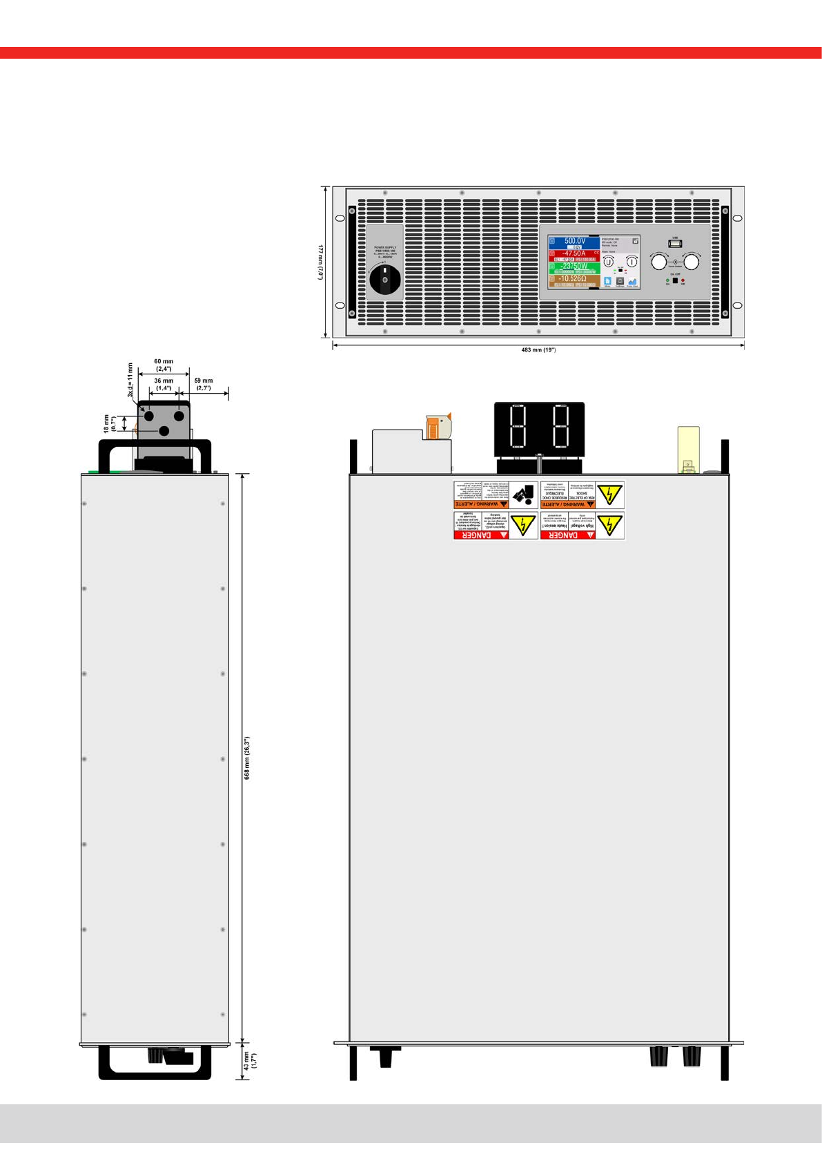
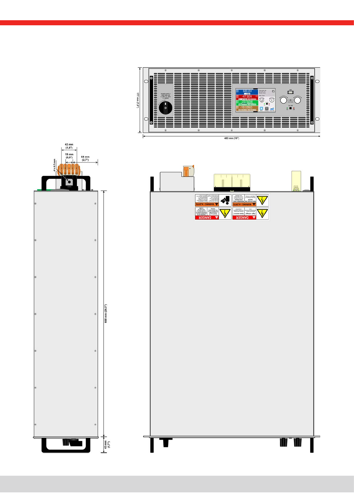
Dimensions (W x H x D) Enclosure: 19“ x 4U x 668 mm (26.3 in)
Total: 19“ x 4U x min. 785 mm (31 in)
Weight 50 kg (110 lb)
Weight with water cooling 56 kg (126 lb)

© EPS Stromversorgung in 2022, this information is subject to change without notice 1430000800_manual_psb_10000_4u_30kw_en_04
Technical speci cations PSB 10010-1000 PSB 10060-1000 PSB 10080-1000 PSB 10200-420
DC output
Voltage range 0 - 10 V 0 - 60 V 0 - 80 V 0 - 200 V
Ripple in CV (rms) ≤25 mV (BW 300 kHz) ≤25 mV (BW 300 kHz) ≤25 mV (BW 300 kHz) ≤40 mV (BW 300 kHz)
Ripple in CV (pp) ≤320 mV (BW 20 MHz) ≤320 mV (BW 20 MHz) ≤320 mV (BW 20 MHz) ≤300 mV (BW 20 MHz)
UMin for IMax (sink) 0.62 V 0.62 V 0.62 V 1.8 V
Current range 0 - 1000 A 0 - 1000 A 0 - 1000 A 0 - 420 A
Power range 0 - 10000 W 0 - 30000 W 0 - 30000 W 0 - 30000 W
Resistance range 0.003 Ω - 5 Ω 0.003 Ω - 5 Ω 0.003 Ω - 5 Ω 0.0165 Ω - 25 Ω
Output capacitance 25380 μF 25380 μF 25380 μF 5400 μF
Effi ciency sink/source (up to) 93.8% *1 95.1% *1 95.5% *1 95.3% *1
Insulation
Negative DC pole <-> PE ±600 V DC ±600 V DC ±600 V DC ±1000 V DC
Positive DC pole <-> PE +600 V DC +600 V DC +600 V DC +1000 V DC
Article numbers
Standard 30000810 30000800 30000801 30000802
Standard + Water Cooling 30000830 30000820 30000821 30000822
Technical speci cations PSB 10360-240 PSB 10500-180 PSB 10750-120 PSB 10920-125
DC output
Voltage range 0 - 360 V 0 - 500 V 0 - 750 V 0 - 920 V
Ripple in CV (rms) ≤55 mV (BW 300 kHz) ≤70 mV (BW 300 kHz) ≤200 mV (BW 300 kHz) ≤250 mV (BW 300 kHz)
Ripple in CV (pp) ≤320 mV (BW 20 MHz) ≤350 mV (BW 20 MHz) ≤800 mV (BW 20 MHz) ≤1200 mV (BW 20 MHz)
UMin for IMax (sink) 2.5 V 1.1 V 1.2 V 2 V
Current range 0 - 240 A 0 - 180 A 0 - 120 A 0 - 125 A
Power range 0 - 30000 W 0 - 30000 W 0 - 30000 W 0 - 30000 W
Resistance range 0.05 Ω - 90 Ω 0.08 Ω - 170 Ω 0.2 Ω - 370 Ω 0.25 Ω - 550 Ω
Output capacitance 1800 μF 675 μF 450 μF 100 μF
Effi ciency sink/source (up to) 95.8% *1 96.5% *1 96.5% *1 96.5% *1
Insulation
Negative DC pole <-> PE ±1000 V DC ±1500 V DC ±1500 V DC ±1500 V DC
Positive DC pole <-> PE +1000 V DC +2000 V DC +2000 V DC +2000 V DC
Article numbers
Standard 30000803 30000804 30000805 30000809
Standard + Water Cooling 30000823 30000824 30000825 30000829
*1 At 100% power and 100% output voltage
*1 At 100% power and 100% output voltage

© EPS Stromversorgung in 2022, this information is subject to change without notice 1530000800_manual_psb_10000_4u_30kw_en_04
Technical speci cations PSB 11000-80 PSB 11500-60 PSB 12000-40
DC output
Voltage range 0 - 1000 V 0 - 1500 V 0 - 2000 V
Ripple in CV (rms) ≤300 mV (BW 300 kHz) ≤400 mV (BW 300 kHz) ≤500 mV (BW 300 kHz)
Ripple in CV (pp) ≤1600 mV (BW 20 MHz) ≤2400 mV (BW 20 MHz) ≤00 mV (BW 20 MHz)
UMin for IMax (sink) 3.4 V 3.2 V 3.7 V
Current range 0 - 80 A 0 - 60 A 0 - 40 A
Power range 0 - 30000 W 0 - 30000 W 0 - 30000 W
Resistance range 0.4 Ω - 650 Ω 0.8 Ω - 1500 Ω 1.7 Ω - 2700 Ω
Output capacitance 200 μF 75 μF 50 μF
Effi ciency sink/source (up to) 95.8% *1 96.5% *1 96.5% *1
Insulation
Negative DC pole <-> PE ±1500 V DC ±1500 V DC ±1500 V DC
Positive DC pole <-> PE +2000 V DC +2000 V DC +2000 V DC
Article numbers
Standard 30000806 30000807 30000808
Standard + Water Cooling 30000826 30000827 30000828
*1 At 100% power and 100% output voltage
© EPS Stromversorgung in 2022, this information is subject to change without notice 1630000800_manual_psb_10000_4u_30kw_en_04
1.8.4 Views
1.8.4.1 Technical drawings PSB 10000 4U ≤200 V

© EPS Stromversorgung in 2022, this information is subject to change without notice 1730000800_manual_psb_10000_4u_30kw_en_04
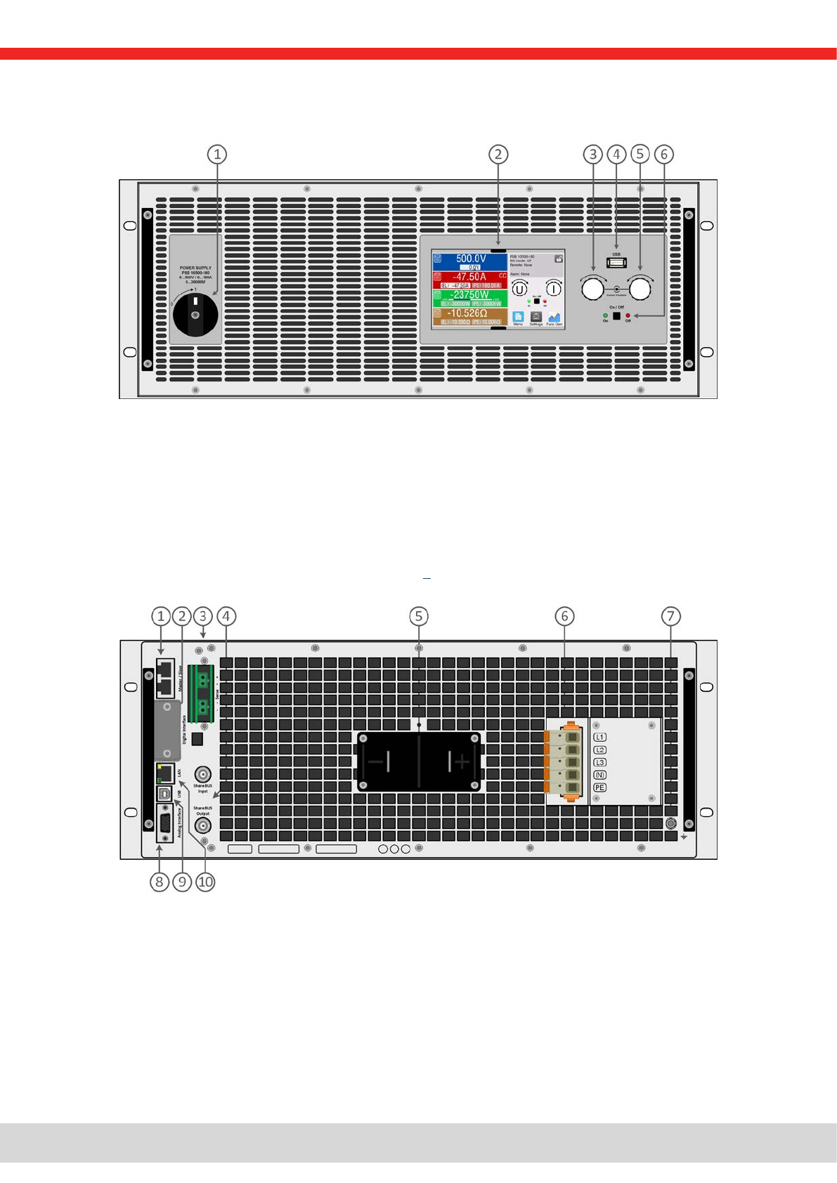
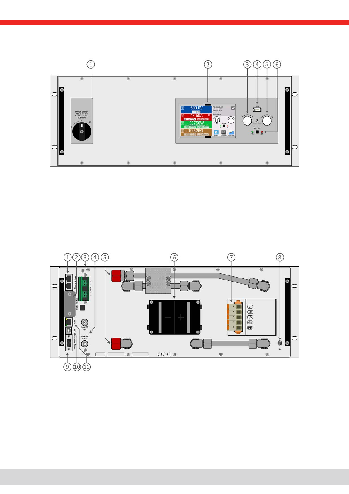
1.8.4.2 Front panel description PSB 10000 4U
1.8.4.3 Rear panel description PSB 10000 4U <200 V
1. Power switch
2. TFT control interface, interactive operation and display
3. Rotary knob with push-button action, for settings and control
4. USB host, uses USB sticks for data logging and sequencing
5. Rotary knob with push-button action, for settings and control
6. On / Off push-button with LED status display
1. Master-Slave bus connectors to set up a system for parallel connection
2. Slot for interfaces
3. Remote sense connectors
4. Share bus connectors to set up a system for parallel connection
5. DC output terminal (copper blades)
6. AC input terminal
7. Grounding connection screw (PE)
8. Connector (DB15 female) for isolated analog programming, monitoring and other functions
9. USB interface
10. Ethernet interface
© EPS Stromversorgung in 2022, this information is subject to change without notice 1830000800_manual_psb_10000_4u_30kw_en_04
1.8.4.4 Technical drawings PSB 10000 4U ≥360 V
© EPS Stromversorgung in 2022, this information is subject to change without notice 1930000800_manual_psb_10000_4u_30kw_en_04
1.8.4.5 Front panel description PSB 10000 4U
1.8.4.6 Rear panel description PSB 10000 4U >360 V
1. Power switch
2. TFT control interface, interactive operation and display
3. Rotary knob with push-button action, for settings and control
4. USB host, uses USB sticks for data logging and sequencing
5. Rotary knob with push-button action, for settings and control
6. On / Off push-button with LED status display
1. Master-Slave bus connectors to set up a system for parallel connection
2. Slot for interfaces
3. Remote sense connectors
4. Share bus connectors to set up a system for parallel connection
5. DC output terminal (copper blades)
6. AC input terminal
7. Grounding connection screw (PE)
8. Connector (DB15 female) for isolated analog programming, monitoring and other functions
9. USB interface
10. Ethernet interface
© EPS Stromversorgung in 2022, this information is subject to change without notice 2030000800_manual_psb_10000_4u_30kw_en_04
1.8.4.7 Front panel description PSB 10000 4U with Water Cooling option
1.8.4.8 Rear panel description PSB 10000 4U with Water Cooling option
1. Power switch
2. TFT control interface, interactive operation and display
3. Rotary knob with push-button action, for settings and control
4. USB host, uses USB sticks for data logging and sequencing
5. Rotary knob with push-button action, for settings and control
6. On / Off push-button with LED status display
1. Master-Slave bus connectors to set up a system for parallel connection
2. Slot for interfaces
3. Remote sense connectors
4. Share bus connectors to set up a system for parallel connection
5. Inlets and outlets for water-cooling
6. DC output terminal (copper blades)
7. AC input terminal
8. Grounding connection screw (PE)
9. Connector (DB15 female) for isolated analog programming, monitoring and other functions
10. USB interface
11. Ethernet interface
Table of contents
Other EPS Power Supply manuals

EPS
EPS PSI 10000 4U User manual

EPS
EPS PSI 9000 T Series User manual

EPS
EPS BC 800 R Series User manual

EPS
EPS PSI 10000 4U User manual

EPS
EPS PS 8016-20 DT User manual

EPS
EPS PSI 800 R Series User manual

EPS
EPS PS 880-170 R User manual

EPS
EPS NEXUS User manual

EPS
EPS EPS/HC 40030-60 User manual

EPS
EPS PSI 9000 2U Series User manual


Popular Power Supply manuals by other brands


Keithley
Keithley 2302 instruction manual

SilverStone
SilverStone ST400 STRIDER user guide

Optimal Power
Optimal Power OPR Power Series manual

National Instruments
National Instruments NI PXIe-4113 CALIBRATION PROCEDURE

Kikusui
Kikusui PLZ2405WB Operation manual

Festo
Festo VMPAF-FB-SP Series Assembly instructions


