FENDT Vario 800 Series User manual

Workshop Service Manual
FENDT 800 Vario S4
FENDT 822 Vario S4
839 .. 1001-
FENDT 824 Vario S4
840 .. 1001-
FENDT 826 Vario S4
841 .. 1001-
FENDT 828 Vario S4
842 .. 1001-
Marktoberdorf
AGCO GmbH - Johann-Georg-Fendt-Str. 4 - D-87616 Marktoberdorf
FENDT is a worldwide brand of AGCO
© AGCO 2017
September 2017
X990.005.530.013
5205
English

Subject to changes and additions
IMPORTANT:
This document is valid from the chassis number noted. The last valid chassis number could not be
determined at the time of creation. Use AGCONET or contact FENDT technical service to make sure
whether a current wiring diagram set is available with an updated chassis number range.
Due to further developments to the vehicle, the content of this document is subject to change.
The relevant accident prevention regulations must be observed, as must as any generally acknowledged
safety, industrial medicine and traffic regulations. The manufacturer does not accept liability for damage
resulting from unauthorized modifications to the machine.
Property of AGCO GmbH.
Any disclosure to third parties—either in return for payment or free of charge—is prohibited.
GUID-A9F19094-7C5D-44B1-84C7-6D95E6AC44E4 [V2]
.
FENDT 800 Vario S4
X990.005.530.013
Find manuals at https://best-manuals.com

FENDT 800 Vario S4
1 Overall system/tractor ....................................................1-1
1.1 General ........................................................... 1-3
1.1.1 Notes on documentation ...........................................1-3
1.1.2 Safety instructions and measures .....................................1-4
1.1.3 Importance of and position of the safety decals .......................... 1-7
1.1.4 Note on hydraulics ...............................................1-18
1.1.5 Assignment table FENDT T types to the EU Type Approval Number ...........1-18
1.1.6 Support points for jack and support stands .............................1-19
1.1.7 Location of the identification plates ..................................1-20
1.1.8 Biodegradable hydraulic oil .........................................1-23
1.1.9 Tightening torque for screws with a galvanized surface ....................1-24
1.1.10 Tightening torque for screws and bolts with VDA coating .................1-25
1.2 Technical specification ............................................1-27
1.2.1 Technical data: 0000 general .......................................1-27
1.2.2 Technical data: 1000 - Transmission ..................................1-28
1.2.3 Technical data: 2000 - Diesel engine ..................................1-34
1.2.4 Technical data: 3000 front axle ......................................1-42
1.2.5 Technical data: 5500 air conditioning system/8100 cab/8600 EPC control valve ...1-44
1.2.6 Technical data: 8800 compressed air system / 9000 electrical system / 9200 front
power lift ..........................................................1-45
1.2.7 Technical data: 9600 hydraulic equipment ..............................1-46
1.3 Fault code tables 800 / 900 Vario S4 .................................2-1
1.3.1 Fault code tables ............................................2-3
1.3.1.1 Confirming, calling up, deleting fault codes .......................2-3
1.3.1.2 Fault code 00.0.00 .........................................2-5
1.3.1.3 Fault code 01.0.00 .........................................2-8
1.3.1.4 Fault code 02.1.00 ........................................2-14
1.3.1.5 Error code 03.1.00 ........................................2-16
1.3.1.6 Fault code 04.1.00 ........................................2-18
1.3.1.7 Fault code 05.1.00 ........................................2-31
1.3.1.8 Fault code 06.1.00 ........................................2-36
1.3.1.9 Fault code 07.1.00 ........................................2-41
1.3.1.10 Fault code 08.1.00 .......................................2-43
1.3.1.11 Fault code 09.1.00 .......................................2-49
1.3.1.12 Fault code 0A.1.00 .......................................2-54
1.3.1.13 Fault code 0B.1.00 .......................................2-73
1.3.1.14 Fault code 0D.1.00 .......................................2-76
1.3.1.15 Fault code 0E.1.00 .......................................2-79
1.3.1.16 Error code 0F.1.00 .......................................2-84
1.3.1.17 Fault code 10.1.00 .......................................2-88
1.3.1.18 Fault code 12.1.00 .......................................2-89
1.3.1.19 Fault code 15.1.00 .......................................2-97
1.3.1.20 Fault code 17.1.00 .......................................2-98
1.3.1.21 Fault code 18.01.00 ......................................2-99
1.3.1.22 Fault code 1D.1.00 ......................................2-102
1.3.1.23 Fault code 1F.1.00 ......................................2-115
1.3.1.24 Fault code 20.1.00 ......................................2-116
1.3.1.25 Calibration fault codes ....................................2-121
1.4 Component position .............................................1-131
1.4.1 Electrical/electronic components - A .................................1-131
Table of contents
FENDT 800 Vario S4
X990.005.530.013
Find manuals at https://best-manuals.com

1.4.2 Electrical/electronic components - B .................................1-137
1.4.3 Electrical/electronic components - E .................................1-149
1.4.4 Electrical/electronic components - F .................................1-160
1.4.5 Electrical/electronic components - G .................................1-160
1.4.6 Electrical/electronic components - H .................................1-161
1.4.7 Electrical/electronic components – K .................................1-162
1.4.8 Electrical/electronic components - M ................................1-165
1.4.9 Electrical/electronic components - R .................................1-168
1.4.10 Electrical/electronic components - S ................................1-170
1.4.11 Electrical/electronic components – U ...............................1-177
1.4.12 Electrical/electronic components - X (001–1000) .......................1-178
1.4.13 Electrical/electronic components - X (1001–2000) ......................1-184
1.4.14 Electrical/electronic components - X (2001–4000) ......................1-190
1.4.15 Electrical/electronic components - X (4001–6000) ......................1-193
1.4.16 Electrical/electronic components - Y ................................1-225
1.4.17 Hydraulic components ..........................................1-233
1.5 Calibrations ......................................................1-266
1.5.1 Adjustments — General ..........................................1-266
1.5.1.1 Calibration notes .........................................1-266
1.5.2 Adjustments — Gearbox .........................................1-266
1.5.2.1 Calibration 4001 clutch pedal ................................1-266
1.5.2.2 Calibration 4002: Hand throttle ..............................1-269
1.5.2.3 Calibration 4003: Travel range selector .........................1-272
1.5.2.4 Calibration 4005 driving pedal ...............................1-276
1.5.2.5 Calibration 4007: Transmission ratio characteristic ................1-278
1.5.2.6 Calibration 4009: Turbo-clutch function ........................1-282
1.5.2.7 Calibration 4010 driving pedal resolution .......................1-286
1.5.3 Adjustments — Sensors and functions ...............................1-289
1.5.3.1 Calibration 1001 crossgate lever .............................1-289
1.5.3.2 Calibration 1003/1004/1005/1006 Linear modules .................1-295
1.5.3.3 Calibration 2401 steering angle sensor .........................1-299
1.5.3.4 Calibration 2401 - checking the calibration accuracy ...............1-303
1.5.3.5 Calibration 2403: Steering valve, when required. ..................1-305
1.5.3.6 Calibration 6034: Rear PTO clutch ............................1-309
1.5.3.7 Calibration 7034 front PTO clutch ............................1-312
1.5.3.8 Calibration 7666: Front axle suspension ........................1-315
1.5.3.9 Calibration 8001 rear EPC - depth control .......................1-318
1.5.3.10 Calibration 8002: Rear EPC - position control ...................1-321
1.5.3.11 Calibration 9001 front EPC - depth control .....................1-325
1.5.3.12 Calibration 9002 front EPC - position control ....................1-328
1.5.3.13 Heating valve calibration - automatic air-conditioning system ........1-331
1.5.3.14 Speed display calibration ..................................1-333
3 Gearbox ................................................................. 3-1
3.1 Gearbox control ................................................... 3-3
3.1.1 Transmission control system functional sequence .........................3-3
3.1.2 Gearbox hydraulics wiring diagram — 842.100.000.002 .....................3-7
3.1.3 Transmission function diagram ......................................3-10
3.1.4 Position of transmission components .................................3-16
3.1.5 Hydraulic pressure measuring points on transmission and comfort controls .....3-23
3.1.6 Measuring transmission pressure ....................................3-26
3.1.7 Transmission pressure measurement (fax template) ......................3-26
3.1.8 Transmission comfort control functions pressure measurement report: Fax
template. ..........................................................3-28
3.1.9 Test the clutch/turbo-clutch valve ....................................3-29
3.2 Differential unit ...................................................3-32
3.2.1 Dismantling differential ...........................................3-32
Table of contents
FENDT 800 Vario S4
X990.005.530.013
Find manuals at https://best-manuals.com

3.2.2 Assemble the differential ..........................................3-37
3.2.3 Dismantling the pinion shaft ........................................3-43
3.2.4 Adjusting and fitting the pinion shaft ..................................3-47
3.2.5 Install differential and set backlash ...................................3-55
3.3 Final drive axle ....................................................3-61
3.3.1 Remove final drive axle ...........................................3-61
3.3.2 Install final drive axle .............................................3-65
3.3.3 Dismantling and reassembling final drive axle ...........................3-69
3.3.4 Technical drawing of drive axle with TPMS .............................3-84
3.4 Brake system .....................................................3-86
3.4.1 Warning ......................................................3-86
3.4.2 Hydraulic brake system: single-circuit brake, 1 pedal ......................3-87
3.4.3 Hydraulic brake system: single-circuit brake, 2 pedals .....................3-90
3.4.4 Hydraulic brake system: dual-circuit, 1 pedal ............................3-93
3.4.5 Connection assignment on the brake valve block for the trailer spool valve ......3-96
3.4.6 Hand brake emergency release .....................................3-99
3.4.7 Check hydraulic brake system .....................................3-100
3.4.8 Technical drawing of rear wheel brake ...............................3-103
3.4.9 Component location - Brake .......................................3-104
3.4.10 Dismantle rear wheel brake ......................................3-108
3.4.11 Install rear wheel brake .........................................3-110
3.4.12 Bleed the hydraulic brake system ..................................3-114
3.4.13 Adjust the S105/106 brake switch .................................3-116
3.4.14 Check the pilot control for the pneumatic trailer brake ...................3-118
3.5 Vario insert ......................................................3-119
3.5.1 Remove the Vario insert ..........................................3-119
3.5.2 Fit the Vario insert ..............................................3-129
3.5.3 Top up the transmission oil .......................................3-139
3.5.4 Remove actuator shaft ...........................................3-140
3.5.5 Fit actuator shaft ...............................................3-142
3.5.6 Remove connecting rod ..........................................3-146
3.5.7 Fit coupling rod ................................................3-148
3.5.8 Dismantle control housing ........................................3-151
3.5.9 Fit control housing ..............................................3-153
3.5.10 Install B014 hydrostatic collecting shaft sensor ........................3-155
3.5.11 Install B015 bevel pinion sensor ...................................3-158
3.6 Cardan brake ....................................................3-161
3.6.1 Technical drawing of Cardan shaft brake ..............................3-161
3.6.2 Remove cardan shaft brake .......................................3-163
3.6.3 Installing cardan shaft brake .......................................3-167
3.7 Front PTO .......................................................3-178
3.7.1 Front PTO valve block ...........................................3-178
3.7.2 Front PTO transmission ..........................................3-179
3.7.3 Front PTO drive ................................................3-180
3.7.4 Remove front PTO clutch .........................................3-182
3.7.5 Fit the front PTO clutch ..........................................3-190
3.7.6 Remove front PTO pump .........................................3-197
3.7.7 Install front PTO pump ...........................................3-199
3.7.8 Remove front PTO stub shaft ......................................3-201
3.7.9 Install front PTO stub shaft .......................................3-203
3.8 Rear PTO ........................................................3-204
3.8.1 Technical drawing of rear PTO .....................................3-204
3.8.2 Remove of rear PTO clutch .......................................3-207
3.8.3 Install rear PTO clutch ...........................................3-215
3.8.4 Remove and dismantle rear PTO transmission .........................3-224
3.8.5 Install rear PTO transmission ......................................3-229
3.9 Front wheel drive ................................................3-235
Table of contents
FENDT 800 Vario S4
X990.005.530.013
Find manuals at https://best-manuals.com

3.9.1 Technical drawing: Front-wheel drive shaft ............................3-235
3.9.2 Removing and dismantling the front wheel drive clutch ...................3-237
3.9.3 Fit the front wheel drive clutch .....................................3-241
3.10 Hydrodamp .....................................................3-249
3.10.1 Remove the hydrodamp .........................................3-249
3.10.2 Fit the hydrodamp .............................................3-251
4 Engine ...................................................................4-1
4.1 Engine ............................................................ 4-3
4.1.1 Faults on the Common Rail diesel engine (without fault code) ................4-3
4.1.2 Special tools for diesel engines (Deutz) .................................4-7
4.1.3 Fax template for determining the specific engine lubricating oil consumption ....4-33
4.1.4 Determining engine power - comparison of standards and directives ..........4-37
4.1.5 Calculating the fuel consumption of a diesel engine .......................4-38
4.1.6 PTO power measurement .........................................4-46
4.1.7 General description of the common rail system ..........................4-48
4.1.8 Emergency operation (emergency function) ............................4-51
4.1.9 Deutz TCD/TTCD diesel engines: Automatic system calibration ..............4-52
4.1.10 A099 - engine control unit ........................................4-71
4.1.11 B055 - foot throttle sensor ........................................4-75
4.1.12 B085 camshaft speed sensor ......................................4-76
4.1.13 B086 rail pressure sensor .........................................4-78
4.1.14 B087 fuel low pressure sensor .....................................4-80
4.1.15 B088 - sensor, crankshaft speed ....................................4-81
4.1.16 B089 engine temperature sensor (Deutz) .............................4-82
4.1.17 B090 oil pressure sensor .........................................4-83
4.1.18 B091 - water in fuel sensor .......................................4-83
4.1.19 B092 charge air pressure/temperature sensor ..........................4-85
4.1.20 Starter control .................................................4-86
4.2 Cylinder head .....................................................4-88
4.2.1 Adjust the valves ................................................4-88
4.2.2 Remove and install the injector and injector sleeve .......................4-98
4.3 Cooling system ..................................................4-125
4.3.1 Coolant circuit TTCD 6.1 .........................................4-125
4.4 Fuel system ......................................................4-127
4.4.1 Fuel system ..................................................4-127
4.4.2 Pressure checking (Deutz TCD 4.1/6.1/7.8) common rail system "High-pressure
system 1600/2000 bar operating pressure", test injector, Y091 dispensing unit, test high-
pressure pump .....................................................4-128
4.4.3 Water sedimentor (pre-filter) ......................................4-192
4.4.4 Fuel pump ....................................................4-193
4.4.5 Y091 - dispensing unit (fuel) .......................................4-193
4.4.6 High-pressure pump (PF 45) .......................................4-197
4.4.7 High-pressure accumulator: Common rail .............................4-198
4.4.8 Design and function of the high-pressure relief valve .....................4-199
4.4.9 Y095 to Y101 - Injectors 1 to 6 .....................................4-200
4.4.10 Measuring fuel return pressure ....................................4-204
4.4.11 Measuring low fuel pressure .....................................4-211
4.4.12 Measuring low fuel pressure at the Y091 dispensing unit .................4-215
4.4.13 Removing and installing the high-pressure limiting valve and rail pressure sensor 4-217
4.4.14 Bleeding air from the fuel system .................................4-220
4.5 Exhaust gas system ..............................................4-222
4.5.1 Charge air system and exhaust gas after-treatment ......................4-222
4.5.2 CSF particulate filter for reducing soot particles .........................4-228
4.5.3 SCR catalytic converter ..........................................4-233
4.5.4 Components of the exhaust after-treatment system .....................4-238
Table of contents
FENDT 800 Vario S4
X990.005.530.013
Find manuals at https://best-manuals.com

4.5.5 Fault analysis on A084 supply module / Y120 "AdBlue" (read faults / flush / check
SCR system) ......................................................4-243
4.5.6 AdBlue dosing system diagnostics using the FENDIAS diagnostics program
(Deutz-Serdia) ......................................................4-281
4.5.7 AdBlue dosing system: AdBlue consumption and fuel consumption ..........4-300
5 Overall system/front axle ................................................. 5-1
5.1 Suspension ........................................................5-3
5.1.1 Functional plans .................................................5-3
5.1.2 Disassemble and reassemble suspension cylinder .......................5-10
5.2 Cardan shaft ......................................................5-12
5.2.1 Technical drawing: Front-wheel drive shaft .............................5-12
6 Steering ................................................................. 6-1
6.1 Steering ...........................................................6-3
6.1.1 Steering hydraulics ...............................................6-3
6.1.2 Steering hydraulics ...............................................6-4
6.1.3 Steering monitoring ...............................................6-8
6.1.4 Remove the steering servo unit. .....................................6-10
6.1.5 Install the steering servo unit .......................................6-13
6.1.6 Remove the RÜFA steering servo unit ................................6-16
7 Vehicle layout ............................................................7-1
7.1 Layout ............................................................ 7-3
7.1.1 Remove, install and repair turntable from operator's seat (Rüfa) ...............7-3
8 Overall system/air conditioning system ....................................8-1
8.1 Air-conditioning system ............................................8-3
8.1.1 Diagram: Automatic air conditioning system .............................8-3
8.1.2 Air conditioning unit service hatch ....................................8-6
8.1.3 Removing the air conditioning unit (HVAC) ..............................8-8
8.1.4 Installing the air conditioning unit (HVAC) ..............................8-13
8.1.5 Removing the air box (B071, M015, M016) .............................8-18
8.1.6 Installing the air box ..............................................8-20
8.1.7 Assembly and disassembly of the dryer module for the air conditioning condenser
..................................................................8-23
9 Cab ......................................................................9-1
9.1 Cab ...............................................................9-3
9.1.1 Reverse drive control function and operation ............................ 9-3
9.1.2 Remove the cab .................................................9-7
9.1.3 Attaching the cab ...............................................9-15
9.1.4 Glue in the front windscreen .......................................9-22
9.1.5 Tightening torques of the door furniture ...............................9-28
10 Power lift/EPC electro-hydraulic control ..................................10-1
10.1 Power lift/EPC electro-hydraulic control ...........................10-3
10.1.1 Slip control system operation and function ............................10-3
10.1.2 Functional description of B031/B032 - draft sensing pin left/right ............10-4
10.1.3 EPC valves ...................................................10-8
10.1.4 Functional plans ...............................................10-13
10.1.5 Lower link stabilizer functional plan .................................10-25
10.1.6 Remove the rear EPC valve ......................................10-26
10.1.7 Fit the rear EPC valve ...........................................10-29
10.1.8 Dismantle the rear pressure relief valve DW Y062 ......................10-34
10.1.9 Assemble the rear pressure relief valve DW Y062 ......................10-35
Table of contents
FENDT 800 Vario S4
X990.005.530.013
Find manuals at https://best-manuals.com

10.2 Power lift control ...............................................10-36
10.2.1 Technical drawing of the hydr. lower linkage support ....................10-36
10.2.2 Remove the lower linkage stabilizer solenoid valve Y082/Y083 .............10-40
10.2.3 Install the Y082/Y083 lower link stabilizer solenoid valves ................10-41
11 Overall system/compressed air system ..................................11-1
11.1 Compressed air system ...........................................11-3
11.1.1 Compressed air system (area: trailer brake) ............................11-3
11.1.2 Compressed air system diagram – 842.880.000.001_b ..................11-10
11.1.3 Compressed air system diagram - 842.880.000.002 .....................11-13
11.1.4 Tightening torques for compressed-air connection system ................11-15
11.1.5 "VarioGrip" tire pressure monitoring system, function and layout ............11-17
12 Electrical system .......................................................12-1
12.1 Electrical system .................................................12-5
12.1.1 Circuit diagrams for A050 - basic control ECU ..........................12-5
12.2 Measure and test - A components ................................12-12
12.2.1 A007 - instrument panel .........................................12-12
12.2.2 A009 - actuator unit ............................................12-24
12.2.3 Installing A009 actuator unit ......................................12-32
12.2.4 A011 - radar sensor ............................................12-38
12.2.5 A013 - circuit board, microfuses ...................................12-41
12.2.6 A036 - "dashboard" control panel ...................................12-47
12.2.7 A038 - relay; +supply; K BUS .....................................12-51
12.2.8 A038 - head light, side light, direction indicator ........................12-62
12.2.9 A038 - horn, rotating beacon, wide vehicle marker ......................12-68
12.2.10 A038 - work lights ............................................12-70
12.2.11 A038 - interior lighting .........................................12-73
12.2.12 A038 - mirror heating, rear window heating, windscreen heating; windscreen
wipers ...........................................................12-75
12.2.13 A038 - automatic air conditioning system (heating, air conditioning, ventilation) 12-79
12.2.14 A038 - sockets ...............................................12-85
12.2.15 A038 - Starter and tank pump ....................................12-94
12.2.16 A038 - reverse drive control (Rüfa) ................................12-97
12.2.17 A038 Work light activation .....................................12-103
12.2.18 Test A038 with 160-pin adapter box ..............................12-111
12.2.19 A050 - basic control unit ECU ...................................12-114
12.2.20 A050 - CAN BUS (K BUS, G BUS, V BUS, ISO BUS) ...................12-118
12.2.21 Test A050 with 160-pin adapter box ..............................12-126
12.2.22 A077 - immobilizer ECU: Functional description ......................12-128
12.2.23 A077 - immobilizer ECU .......................................12-129
12.2.24 A082 - nitrogen oxide NOx sensor 1, upstream of SCR (Not G3) ..........12-131
12.2.25 A083 - nitrogen oxide NOx sensor 2, downstream of SCR (Not G3) ........12-132
12.2.26 A084 - AdBlue module (Not G3) .................................12-133
12.2.27 A087 - tire pressure monitoring system (TPMS) ......................12-135
12.2.28 A099 - ECU engine control unit (EDC 17) ...........................12-137
12.2.29 Test A099 with 160-pin adapter box ..............................12-143
12.2.30 A100 - MFA, multifunction armrest ...............................12-145
12.2.31 Test A100 with 160-pin adapter box ..............................12-152
12.2.32 A133 - air intake throttle ECU ...................................12-154
12.2.33 A134 - exhaust gas recirculation ECU .............................12-155
12.2.34 A136 - wastegate ECU ........................................12-157
12.2.35 A177 - AGCO Connectivity Module (ACM) ..........................12-158
12.3 Measure and test - B components ...............................12-160
12.3.1 B002 - front PTO speed sensor ...................................12-160
12.3.2 B003 - front axle suspension position sensor .........................12-161
12.3.3 B004 - vacuum switch (air filter) ..................................12-162
Table of contents
FENDT 800 Vario S4
X990.005.530.013
Find manuals at https://best-manuals.com

12.3.4 B007 - fuel level sensor ........................................12-164
12.3.5 B008 - High pressure sensor 1 ...................................12-166
12.3.6 B009 - discharge temperature sensor ..............................12-168
12.3.7 B013 - hydraulic oil temperature sensor ............................12-169
12.3.8 B014 - Collecting shaft speed sensor ..............................12-171
12.3.9 B015 - bevel pinion sensor ......................................12-172
12.3.10 B016 - travel speed range detection sensor .........................12-174
12.3.11 B017 - clutch pedal sensor .....................................12-175
12.3.12 B020 - rear PTO (stub shaft) speed sensor ..........................12-176
12.3.13 B021 - rear PTO clutch speed sensor .............................12-177
12.3.14 B031 - right draft sensing pin ...................................12-179
12.3.15 B032 left-hand draft sensing pin sensor ............................12-180
12.3.16 B039 - high pressure sensor 2 ..................................12-182
12.3.17 B040 - Front power lift position sensor ............................12-184
12.3.18 B055 - foot throttle sensor .....................................12-185
12.3.19 B060 compressed air supply sensor ..............................12-186
12.3.20 B071 - output temperature sensor ...............................12-188
12.3.21 B073 - Solar thermal radiation sensor .............................12-189
12.3.22 B074 - interior temperature sensor ...............................12-191
12.3.23 B076 - exterior temperature sensor ...............................12-193
12.3.24 B081 - steering wheel sensor (360°) ..............................12-195
12.3.25 B084 - hydraulic oil level sensor .................................12-197
12.3.26 B085 - camshaft speed sensor ..................................12-199
12.3.27 B086 - rail pressure sensor .....................................12-202
12.3.28 B087 - low fuel pressure sensor .................................12-205
12.3.29 B088 - sensor, crankshaft speed .................................12-207
12.3.30 B089 - engine temperature sensor (Deutz) ..........................12-210
12.3.31 B090 - oil pressure sensor .....................................12-213
12.3.32 B091 - water in fuel sensor .....................................12-215
12.3.33 B092 - boost pressure/charge air temperature sensor .................12-216
12.3.34 B097 - brake pressure sensor ...................................12-219
12.3.35 B102 - AdBlue temperature and level sensor ........................12-222
12.3.36 B105 - Exhaust gas temperature sensor upstream of SCR (Not G3) .......12-225
12.3.37 B145 - rear power lift position sensor .............................12-227
12.3.38 B168 - steering angle sensor ...................................12-228
12.3.39 B187 - evaporator temperature sensor ............................12-229
12.3.40 B191 - Exhaust gas pressure sensor upstream of turbo ................12-231
12.3.41 B192 - CSF differential pressure sensor (Not G3) .....................12-232
12.3.42 B193 - exhaust temperature upstream of CSF sensor (Not G3) ...........12-234
12.3.43 B194 - pressure downstream of CSF sensor (Not G3) .................12-236
12.3.44 B217 - temperature sensor downstream of venturi (Not G3) .............12-237
12.3.45 B218 - venturi differential pressure sensor (Not G3) ...................12-239
12.3.46 B283 - Supply pressure monitoring sensor 2 ........................12-240
12.3.47 B284 - Supply pressure monitoring sensor 1 ........................12-242
12.3.48 B290 - Brake pedal lock sensor ..................................12-244
12.4 Measure and test - CAN bus ....................................12-246
12.4.1 Measure the CAN bus .........................................12-246
12.5 Measure and test - E components ...............................12-249
12.5.1 E050 to E280 - work lights ......................................12-249
12.5.2 E063 - air-dryer heater element (temperature-controlled) ................12-249
12.5.3 E216 - AdBlue heater suction and return line and E217 - AdBlue heater pressure
line .............................................................12-251
12.6 Measure and test - G components ...............................12-253
12.6.1 G001 - battery ...............................................12-253
12.6.2 G002/G004 - right/left alternators .................................12-254
12.7 Measure and test - H components ...............................12-257
12.7.1 H011 - horn .................................................12-257
Table of contents
FENDT 800 Vario S4
X990.005.530.013
Find manuals at https://best-manuals.com

12.8 Measure and test - K components ...............................12-258
12.8.1 K063 - Grid heater flange relay ...................................12-258
12.8.2 K065 - starter relay ............................................12-259
12.8.3 K083 - AdBlue relay ...........................................12-259
12.8.4 K090 - AdBlue module heater relay ................................12-260
12.8.5 K091 - AdBlue heating relay for suction and return line ..................12-261
12.8.6 K092 - AdBlue heating relay for pressure line .........................12-261
12.9 Measure and test - M components ..............................12-262
12.9.1 M001 - starter ...............................................12-262
12.9.2 M003/M005 - front/rear screen washer pumps .......................12-266
12.9.3 M004 - rear wiper motor .......................................12-267
12.9.4 M015/M016 - actuator motor for ventilation air flap ....................12-269
12.9.5 M017 - primary fan ...........................................12-271
12.9.6 M046/M047 - headlight actuator motor (headlight adjustment) ............12-273
12.9.7 M048 - main fan .............................................12-275
12.9.8 M049 - heater valve ...........................................12-277
12.9.9 M054 - cooling water pump .....................................12-278
12.9.10 M055 - front wiper motor ......................................12-279
12.10 Measure and test - S components ..............................12-281
12.10.1 S017 - filter contamination switch ................................12-281
12.10.2 S019 - left external rear PTO button ..............................12-282
12.10.3 S020 - right external rear PTO button .............................12-283
12.10.4 S021/S022 - external front power lift button ........................12-285
12.10.5 S025 - variable displacement pump pressure monitoring switch ..........12-286
12.10.6 S027/S028/S029/S030 - external (rear power lift) buttons ...............12-287
12.10.7 S034 - coolant level switch .....................................12-289
12.10.8 S035 High & low-pressure switch for air conditioning system ............12-290
12.10.9 S045 reverse drive switch .....................................12-291
12.10.10 S047 - engine brake switch ....................................12-293
12.10.11 S053 - driver seat switch .....................................12-293
12.10.12 S067/S068 - external valve button ...............................12-295
12.10.13 S074 - starter lockout switch ..................................12-296
12.10.14 S075 - Wheel driven steering pump flow monitor switch ..............12-298
12.10.15 S080 - hand brake switch .....................................12-299
12.10.16 S085 - reverse drive (RÜFA) actuation switch .......................12-300
12.10.17 S105/S106 - left/right brake switches ............................12-301
12.10.18 S119 - hydraulic oil filter contamination switch ......................12-302
12.10.19 S134 - auxiliary pump pressure monitor switch .....................12-303
12.10.20 S157 - forward/reverse shuttle switch ............................12-304
12.10.21 S174/175 - right-hand external valve actuation button .................12-305
12.11 Measure and test - X components ..............................12-308
12.11.1 X007 - "black" implement socket .................................12-308
12.11.2 X008 - counter input (onboard computer) "blue" ......................12-310
12.11.3 X015 - external control, rear EPC (external position sensor) .............12-313
12.11.4 X015 external control (Area: 3rd and 4th hydraulic circuit) ...............12-315
12.11.5 X015 - external control socket (area: automatic steering axle mode) .......12-316
12.11.6 X017 - front socket (with front power lift only) .......................12-322
12.11.7 X018 - trailer socket ..........................................12-323
12.11.8 X028 - cab ISO socket ........................................12-324
12.11.9 X400 ISO BUS PCB (implement socket) ...........................12-325
12.11.10 X1048 ABS socket (anti-lock system on trailer) ......................12-335
12.12 Measure and test - Y components ..............................12-337
12.12.1 Y002 - travel speed range I solenoid valve ..........................12-337
12.12.2 Y003 - travel speed range II solenoid valve .........................12-338
12.12.3 Y004 clutch/turbo-clutch solenoid valve ............................12-340
12.12.4 Y005 - Speed limiter solenoid valve ...............................12-341
12.12.5 Y008 - rear PTO (clutch) solenoid valve ............................12-343
Table of contents
FENDT 800 Vario S4
X990.005.530.013
Find manuals at https://best-manuals.com

12.12.6 Y009 - 4WD solenoid valve .....................................12-344
12.12.7 Y010 - differential lock solenoid valve .............................12-346
12.12.8 Y011 - front PTO (clutch) solenoid valve ...........................12-347
12.12.9 Y012 - suspension loading/oil preheating solenoid valve ................12-349
12.12.10 Y013 - Suspension lowering solenoid valve ........................12-350
12.12.11 Y021 - raise solenoid valve (standard front power lift) .................12-352
12.12.12 Y021 - front pressure compensator lock valve ......................12-353
12.12.13 Y022 - standard front power lift lowering solenoid valve ...............12-355
12.12.14 Y026/Y027 - rear PTO stage I/II selection solenoid valve ...............12-356
12.12.15 Y032 - control pressure solenoid valve ............................12-358
12.12.16 Y055 - rear pressure compensator lock valve .......................12-359
12.12.17 Y060 - hydraulic oil preheater solenoid valve .......................12-361
12.12.18 Y062 - rear field pressure control solenoid valve .....................12-362
12.12.19 Y063 - wobble stabilizer solenoid valve ...........................12-364
12.12.20 Y065 - Suspension raising solenoid valve ..........................12-365
12.12.21 Y067 - Suspension locking solenoid valve .........................12-367
12.12.22 Y082/Y083 - lock and release lower link stabilizer solenoid valve .........12-368
12.12.23 Y084 - power beyond solenoid valve .............................12-370
12.12.24 Y091 - fuel dispensing unit ....................................12-371
12.12.25 Y092/Y093 - reverse drive (RÜFA) rotation solenoid valves .............12-372
12.12.26 Y095 to Y098, Y100, Y101 - injectors 1 to 6 ........................12-374
12.12.27 Y120 - AdBlue metering valve ..................................12-378
12.12.28 Y168 - front ground pressure control solenoid valve ..................12-380
12.12.29 Y169 - AdBlue tank heater solenoid valve .........................12-382
12.12.30 Y170 - engine brake solenoid valve ..............................12-384
12.12.31 Y176-Y185 ................................................12-385
12.12.32 Y209 - reversible fan (Hägele) ..................................12-387
12.12.33 Y222 - Visco fan (Viscotronic) ..................................12-391
12.12.34 Y241 - Air dryer solenoid valve .................................12-393
13 Hydraulic pump installation .............................................13-1
13.1 Hydraulic pump installation .......................................13-3
13.1.1 Fit wheel-driven emergency steering pump ............................13-3
14 Hydraulic pipes .........................................................14-1
14.1 Hydraulic trailer brake ............................................14-3
14.1.1 Function of the hydraulic trailer brake (French and Italian versions) ...........14-3
14.2 Reverse operation ...............................................14-27
14.2.1 Technical drawing of the turntable (reverse drive) ......................14-27
14.2.2 Seal the turntable .............................................14-33
15 Overall system/hydraulic equipment .....................................15-1
15.1 Hydraulic equipment .............................................15-3
15.1.1 Pressure control — PR (LS pump) ..................................15-3
15.1.2 Pressure measuring points overview ................................15-6
15.1.3 External pressure rise (Power Beyond) ...............................15-7
15.1.4 Test report, fax template .........................................15-8
15.1.5 SB 33 EHS 1 RD spool valves .....................................15-11
15.1.6 Central control block ...........................................15-12
16 Electronics .............................................................16-1
16.1 Electronics ......................................................16-3
16.1.1 Fendt 800 Vario Tier IIIb electronics concept ...........................16-3
16.1.2 Functional description of the A050 basic control ECU ....................16-9
17 Service .................................................................17-1
17.1 Special tools .....................................................17-3
Table of contents
FENDT 800 Vario S4
X990.005.530.013

17.1.1 Special tools ..................................................17-3
17.2 FENDIAS ........................................................17-4
17.2.1 EOL programming ..............................................17-4
17.2.2 Programming the immobilizer - introduction ..........................17-10
17.2.3 Teaching in the vehicle key ......................................17-12
17.2.4 Create activation package .......................................17-16
17.2.5 Apply activation package ........................................17-19
17.2.6 Replace components ...........................................17-22
Table of contents
FENDT 800 Vario S4
X990.005.530.013

1. Overall system/tractor
1.1 General ................................................................1-3
1.1.1 Notes on documentation ................................................1-3
1.1.2 Safety instructions and measures ..........................................1-4
1.1.3 Importance of and position of the safety decals ...............................1-7
1.1.4 Note on hydraulics ....................................................1-18
1.1.5 Assignment table FENDT T types to the EU Type Approval Number ................1-18
1.1.6 Support points for jack and support stands ..................................1-19
1.1.7 Location of the identification plates .......................................1-20
1.1.8 Biodegradable hydraulic oil ..............................................1-23
1.1.9 Tightening torque for screws with a galvanized surface .........................1-24
1.1.10 Tightening torque for screws and bolts with VDA coating ...................... 1-25
1.2 Technical specification .................................................1-27
1.2.1 Technical data: 0000 general ............................................1-27
1.2.2 Technical data: 1000 - Transmission .......................................1-28
1.2.3 Technical data: 2000 - Diesel engine .......................................1-34
1.2.4 Technical data: 3000 front axle ...........................................1-42
1.2.5 Technical data: 5500 air conditioning system/8100 cab/8600 EPC control valve ........1-44
1.2.6 Technical data: 8800 compressed air system / 9000 electrical system / 9200 front power
lift ....................................................................1-45
1.2.7 Technical data: 9600 hydraulic equipment ...................................1-46
1.3 Fault code tables 800 / 900 Vario S4 ......................................2-1
1.3.1 Fault code tables .................................................2-3
1.3.1.1 Confirming, calling up, deleting fault codes ............................2-3
1.3.1.2 Fault code 00.0.00 ..............................................2-5
1.3.1.3 Fault code 01.0.00 ..............................................2-8
1.3.1.4 Fault code 02.1.00 .............................................2-14
1.3.1.5 Error code 03.1.00 .............................................2-16
1.3.1.6 Fault code 04.1.00 .............................................2-18
1.3.1.7 Fault code 05.1.00 .............................................2-31
1.3.1.8 Fault code 06.1.00 .............................................2-36
1.3.1.9 Fault code 07.1.00 .............................................2-41
1.3.1.10 Fault code 08.1.00 ............................................2-43
1.3.1.11 Fault code 09.1.00 ............................................2-49
1.3.1.12 Fault code 0A.1.00 ............................................2-54
1.3.1.13 Fault code 0B.1.00 ............................................2-73
1.3.1.14 Fault code 0D.1.00 ............................................2-76
1.3.1.15 Fault code 0E.1.00 ............................................2-79
1.3.1.16 Error code 0F.1.00 ............................................2-84
1.3.1.17 Fault code 10.1.00 ............................................2-88
1.3.1.18 Fault code 12.1.00 ............................................2-89
1.3.1.19 Fault code 15.1.00 ............................................2-97
1.3.1.20 Fault code 17.1.00 ............................................2-98
1.3.1.21 Fault code 18.01.00 ...........................................2-99
1.3.1.22 Fault code 1D.1.00 ...........................................2-102
1.3.1.23 Fault code 1F.1.00 ...........................................2-115
1.3.1.24 Fault code 20.1.00 ...........................................2-116
1.3.1.25 Calibration fault codes .........................................2-121
1.4 Component position ..................................................1-131
1.4.1 Electrical/electronic components - A ......................................1-131
Table of contents
FENDT 800 Vario S4 1-1
X990.005.530.013

1.4.2 Electrical/electronic components - B ......................................1-137
1.4.3 Electrical/electronic components - E ......................................1-149
1.4.4 Electrical/electronic components - F ......................................1-160
1.4.5 Electrical/electronic components - G ......................................1-160
1.4.6 Electrical/electronic components - H ......................................1-161
1.4.7 Electrical/electronic components – K ......................................1-162
1.4.8 Electrical/electronic components - M .....................................1-165
1.4.9 Electrical/electronic components - R ......................................1-168
1.4.10 Electrical/electronic components - S .....................................1-170
1.4.11 Electrical/electronic components – U ....................................1-177
1.4.12 Electrical/electronic components - X (001–1000) ............................1-178
1.4.13 Electrical/electronic components - X (1001–2000) ...........................1-184
1.4.14 Electrical/electronic components - X (2001–4000) ...........................1-190
1.4.15 Electrical/electronic components - X (4001–6000) ...........................1-193
1.4.16 Electrical/electronic components - Y .....................................1-225
1.4.17 Hydraulic components ...............................................1-233
1.5 Calibrations ...........................................................1-266
1.5.1 Adjustments — General ...............................................1-266
1.5.1.1 Calibration notes ..............................................1-266
1.5.2 Adjustments — Gearbox ..............................................1-266
1.5.2.1 Calibration 4001 clutch pedal .....................................1-266
1.5.2.2 Calibration 4002: Hand throttle ...................................1-269
1.5.2.3 Calibration 4003: Travel range selector ..............................1-272
1.5.2.4 Calibration 4005 driving pedal ....................................1-276
1.5.2.5 Calibration 4007: Transmission ratio characteristic .....................1-278
1.5.2.6 Calibration 4009: Turbo-clutch function .............................1-282
1.5.2.7 Calibration 4010 driving pedal resolution ............................1-286
1.5.3 Adjustments — Sensors and functions ....................................1-289
1.5.3.1 Calibration 1001 crossgate lever ..................................1-289
1.5.3.2 Calibration 1003/1004/1005/1006 Linear modules ......................1-295
1.5.3.3 Calibration 2401 steering angle sensor ..............................1-299
1.5.3.4 Calibration 2401 - checking the calibration accuracy ....................1-303
1.5.3.5 Calibration 2403: Steering valve, when required. .......................1-305
1.5.3.6 Calibration 6034: Rear PTO clutch .................................1-309
1.5.3.7 Calibration 7034 front PTO clutch .................................1-312
1.5.3.8 Calibration 7666: Front axle suspension .............................1-315
1.5.3.9 Calibration 8001 rear EPC - depth control ............................1-318
1.5.3.10 Calibration 8002: Rear EPC - position control ........................1-321
1.5.3.11 Calibration 9001 front EPC - depth control ..........................1-325
1.5.3.12 Calibration 9002 front EPC - position control .........................1-328
1.5.3.13 Heating valve calibration - automatic air-conditioning system .............1-331
1.5.3.14 Speed display calibration .......................................1-333
Table of contents
1-2 FENDT 800 Vario S4
X990.005.530.013

1.1 General
1.1.1 Notes on documentation
To ensure that the information is structured in a user-friendly manner, the service documentation is divided
into the operator's manual and the workshop manual.
The operator's manual includes a general description as well as instructions for all necessary maintenance
work.
Knowledge of the owner's manual is essential to understand the workshop manual. This is particularly
important for safety instructions. The workshop manual describes repairs to assemblies and components
that will require more effort and suitably qualified specialists to carry out.
Note
This workshop manual provides notes for trained technicians to maintain our tractors. Read and observe
the information in this documentation. This will help you prevent accidents and safeguard the
manufacturer's warranty.
The respective accident prevention rules as well as other generally recognized safety and occupational
health rules must be observed.
The tractor is built solely for the purpose defined by the implement manufacturer. Any other type of use is
considered unauthorized. The manufacturer bears no liability for any damage resulting from improper use.
The user bears this risk alone. Intended use includes maintaining operating, service and maintenance
conditions as specified by the manufacturer.
Operation, maintenance and repair of the tractor may only be carried out by people who are familiar with
this equipment and aware of the associated dangers. Ensure that this documentation is available to and
understood by everyone involved in operation, maintenance and repair. Not observing this documentation
can lead to faults, damage and personal injury, for which the manufacturer assumes no liability. The
prerequisite for the tractor being correctly serviced and maintained is the perfect condition and availability
of all necessary equipment, standard tools and general workshop equipment as well as special tools.
Special tools must only be used where absolutely necessary. The tools are displayed where they need to
be used in each case.
The machine must be maintained according to its proper use. Always replace parts with genuine FENDT
spare parts! When ordering parts, please provide the chassis number as per the most up-to-date spare
parts documentation.
Only parts approved by the manufacturer for that specific purpose may be used for any alterations. The
manufacturer will not accept liability for any damage resulting from unauthorized modifications to the
tractor. Non-compliance invalidates the warranty!
Workshops should also refer to documentation on maintenance work and technical data. Once
maintenance is complete, take a test drive to ensure the vehicle's correct operation and road safety.
We reserve the right to make design changes in light of technical developments.
Notes on repairs
The assembly/disassembly instructions shown correspond to the design status at the time the workshop
manual was drawn up.
Further technical development of the product and additions related to different versions may require
alternative working processes that do not pose too many difficulties to trained and qualified specialists.
These assembly/disassembly instructions shall be invalidated upon issue of the next version of this
document.
[V]
GUID-11DBEABB-D4B9-4CA8-9AD9-69470831C9ED [V2]
1. Overall system/tractor
FENDT 800 Vario S4 1-3
X990.005.530.013

1.1.2 Safety instructions and measures
Important notes on work safety
The statutory accident prevention regulations (available from professional associations or specialist shops)
must be observed. These depend on the operating site, operating mode and fuels and lubricants used.
Special protective measures dependent on the respective procedures are specified in the corresponding
repair guidelines and highlighted.
This handbook uses the following safety tips
DANGER: Indicates an impending dangerous situation that will lead to serious injury or
death if not avoided.
WARNING: Indicates a potentially dangerous situation that could lead to serious injury or
death if not avoided.
CAUTION: Indicates a potentially dangerous situation that could lead to minor injury if not
avoided.
Please observe the following when carrying out maintenance or service work to the tractor:
Only the documentation associated with the vehicle (workshop manual and operator's manual) must be
used to complete any pending work.
1. General
• Only briefed personnel may operate the tractor or carry out maintenance work.
•Only use qualified specialists to carry out repairs or service work.
• Nobody may be in the cab while work is being carried out under the jacked-up tractor.
• Relieve pressure from implement lines, e.g. to the front loader.
• All people should keep clear of a lifted, unsecured load (e.g. tilted cab etc.).
• Never open or remove any safety devices while the engine is running.
• Pressurized fluids (fuel or hydraulic oil) escaping under high pressure can penetrate the skin and cause
severe injuries. If this should occur, seek medical advice immediately to avoid the risk of serious
infection.
• Keep at a safe distance from hot areas.
• Pressure accumulator and connected pipes are highly pressurized. Only remove and repair in
accordance with instructions provided in the workshop manual.
• To avoid eye injury, do not look directly at the surface of the activated radar sensor.
• Dispose of oil, fuel and filters properly!
• Specialist knowledge and special fitting tools are required to fit tires.
• Run the tractor for a short time, then retighten all wheel nuts and bolts and check them regularly.
For correct torque values refer to TECHNICAL DATA.
• Before working on the electrical system, always remove the earth strap from the battery. Observe the
following when carrying out electric welding. Before carrying out welding work on tractor or mounted
implements, ensure that both battery terminals are disconnected. Attach the welding appliance's earth
terminal as close to the welding spot as possible.
• Caution is required when dealing with brake fluid and battery acid as these are toxic and corrosive!
• Only use genuine FENDT spare parts.
2. Working on the front-axle suspension
• The front axle suspension pressure lines between the central control block (ZSB) and the suspension
cylinders, and
GUID-719EA5A8-BA46-4FE5-8440-EF61436A3DDA [V1]
1. Overall system/tractor
1-4 FENDT 800 Vario S4
X990.005.530.013

• the cased ASPL, ASPR and ZSP pressure accumulators
DANGER: are under 200 bar pressure, even when the engine is switched off and the
suspension is lowered (= locked).
Safety measures:
Prior to each repair and after releasing or opening in this area, the pressure must be
released manually.
NOTE:
The "Lock suspension/lower suspension" command has no effect!
Even externally energizing the solenoid valves Y013 - lower suspension solenoid valve and Y065 -
suspension raising solenoid valve has no effect!
(There are hydraulic pilot-operated non-return valves built in)
To release pressure:
• Screw in the knurled-head screw on the MVFS
[Y013] - Suspension lowering solenoid valve;
the chassis may be lowered
• Screw in the knurled-head screw on the MVFH
[Y065] - Suspension raising solenoid valve;
the rebound accumulator will be relieved
GUID-EBBBB626-0473-46B7-B630-0AC52F18AD35-high.jpg [High]
Fig. 1
Check:
As the oil temperature rises, the emptying accumulator will make a flowing sound
(barely audible in winter).
3. Working on the brake system
DANGER: The brake system hydraulic
lines remain under pressure even
when the engine has been switched
off!
Safety measures:
Before each repair to the brake
system or when removing the cab,
the pressure must be relieved
manually.
To release pressure:
1. Engine must be off
2. Secure the tractor to prevent it from rolling
away.
3. With the hand brake applied, press the foot
brake 50 times
4. Apply the hand brake 20 times
GUID-2347D0BC-3E24-4869-A351-4AC21CDB351B-high.jpg [High]
Fig. 2
General notes:
1. Overall system/tractor
FENDT 800 Vario S4 1-5
X990.005.530.013

• Always check the brakes before driving.
• Adjustments and repairs to the brake system must be carried out in specialist workshops or by
approved brake repair technicians.
•It must not be possible to brake individual wheels when driving (lock pedals)!
4. Working on the engine
• After switching the engine off, wait 30 seconds before carrying out any work on the fuel system.
• Only start the engine once all safety guards have been attached and nobody is standing in the danger
area.
• Never let the engine run in enclosed spaces with no exhaust gas suction system.
• Cleaning, maintenance and repair work may only be carried out once the engine is switched off and
secured to prevent it starting.
• Injection pipes and high-pressures lines must not be deformed.
• Any damaged injection pipe or high-pressure line must be replaced.
• Do not loosen any injection pipes for high-pressure fuel lines while the engine is running.
• Before carrying out checks to the running engine, always perform a visual check of all high-pressure
components. Suitable protective clothing (e.g. protective goggles) should be worn while doing this.
Leaks indicate potential sources of danger for workshop personnel.
• In the event of leaks to the high-pressure fuel system, always remain out of range of any possible fuel
spray to avoid serious injury.
• Even when no leaks to the high-pressure fuel system can be detected, workshop personnel should
avoid the immediate danger area and wear suitable protective clothing (such as protective goggles)
when carrying out checks to the running engine and during the first test run.
• Smoking is forbidden while carrying out work to the fuel system.
• Do not work in the proximity of sparks or naked flames.
• Never disconnect an injector while the engine is running.
5. Working on the PTO
• Always switch off the engine before fitting or removing the drive shaft. PTO in "0" position!
• When working on the PTO, allow no-one in the vicinity of the rotating PTO or drive shaft.
• Make sure drive shaft and PTO are equipped with shield pipes and protective funnels.
• After deactivating the PTO, it is possible that parts on the mounted implement may continue to run. In
this case, do not get too close to the implement. Work may only be carried out to the implement when
nothing is moving!
• When the drive shaft is removed, cover the PTO shaft with its protective cap.
• Nobody should be in the cab when installing and removing the drive shaft.
Operation of controls for the tractor and mounted implements by people in the cab, especially children,
may result in severe or fatal injury.
6. Working on the front loader
• Before undertaking maintenance work, lower the front loader to the ground, switch off the engine and
remove the ignition key.
• In the event of a collapsed pipe rupture feature, support the load before starting repair work, and slowly
retract the cylinder.
• Check hydraulic hoses and pipes for signs of damage and aging regularly and replace with genuine
spare parts in good time.
• Following installation and repairs, operate the tractor for a short time, then retighten all nuts and bolts
and check them regularly.
• Retighten eccentric bolt for front loader attachment, if necessary.
Disposal
The work described in the operator's manual and workshop manual includes replacing parts, fuel and
lubricants. These renewed parts/fuel/lubricants must be stored, transported and disposed of in accordance
1. Overall system/tractor
1-6 FENDT 800 Vario S4
X990.005.530.013

with regulations. The repairing workshop bears responsibility for this. The disposal encompasses the
recycling and final disposal of parts, fuel and lubricants with recycling having the higher priority. Details
about disposal and monitoring are specified in regional, national and international laws and directives, the
observation of which is the sole responsibility of the repairing workshops.
1.1.3 Importance of and position of the safety decals
The position and importance of the safety decals on the vehicle are explained below:
GUID-04637E4F-8B0E-44B7-A9A1-5405C1AC94D8 [V2]
1. Overall system/tractor
FENDT 800 Vario S4 1-7
X990.005.530.013

Position: Left C-pillar, cab interior
743.810.090.050
WARNING:
Serious injury or death caused by
inadequate compliance with the
Operator's Manual
Inadequate compliance with the
Operator’s Manual can cause damage,
injuries and in serious cases death.
Before operation, make sure that this
Operator's Manual is available on the
vehicle in legible form. The owner is
responsible for providing adequate
training to those personnel who are
entrusted with the vehicle and for
ensuring they are familiar with the
instructions in the Operator’s Manual
and, where applicable, the service
manual. The same applies to those
persons who are both owner and
operator.
Observe all safety notes and
instructions, and execute all measures
correctly and completely at all times.
Position: Left B-pillar, cab interior
743.810.090.100
WARNING:
Serious injury or death caused by
being ejected from the cab
When driving, an improperly closed
door can open. Vehicle occupants not
strapped in or not properly strapped in
can be ejected from the vehicle and
run over. This can cause serious injury
and even death.
Make sure that, during travel, all
vehicle passengers are properly
strapped in at all times.
Position: Left C-pillar, cab interior
743.810.090.060
WARNING:
Serious injury or death caused by
being ejected from the cab
If the vehicle tips over, the door can
open. Vehicle occupants not strapped
in or not properly strapped in can be
ejected from the vehicle. This can
cause serious injury and even death.
Make sure that, during travel, all
vehicle passengers are properly
strapped in at all times.
1. Overall system/tractor
1-8 FENDT 800 Vario S4
X990.005.530.013
This manual suits for next models
4
Table of contents
Other FENDT Tractor manuals

FENDT
FENDT FAVORIT 900 Instruction manual
FENDT
FENDT Vario 700 Series User manual

FENDT
FENDT 916 Vario User manual
FENDT
FENDT 5275 C User manual

FENDT
FENDT 500 Vario S4 User manual
FENDT
FENDT 938 Vario MT User manual
FENDT
FENDT 1149MT User manual
FENDT
FENDT Vario 900 Series User manual

FENDT
FENDT 1149MT User manual
FENDT
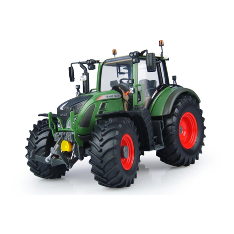
FENDT Vario 712 User manual

