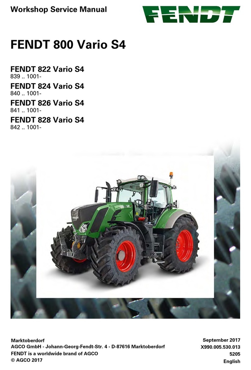
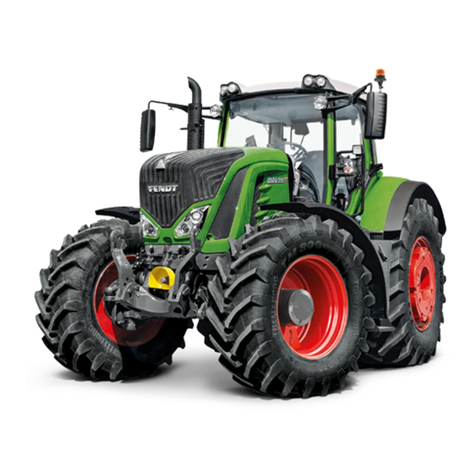
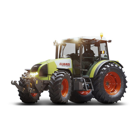
FENDT Vario 900 Series User manual

Workshop Service Manual
FENDT 900 Vario - COM III
919 .. 0101-1000 925 .. 1001- 934 .. 0101-1000
919 .. 1001- 928 .. 0101-1000 934 .. 1001-
922 .. 0101-1000 928 .. 1001-
922 .. 1001- 931 .. 0101-1000
925 .. 0101-1000 931 .. 1001-
FENDT is a worldwide brand of AGCO
'FKVKQP20
No. X990.005.057.01
3 G - en
FENDT 900 Vario COM III - EAME
English
8QNWOG
#)%1)OD*,QJCPP)GQTI(GPFV5VT&/CTMVQDGTFQTH

Crop_this_page
Crop_this_page
All relevant accident prevention regulations and all generally accepted safety, health and
road traffic regulations must be strictly observed. The manufacturer does not accept liability
for damage resulting from unauthorised modifications.
Changes and additions reserved!
PSD 3356 G - en
AGCO GmbH
Johann-Georg-Fendt-Str. 4 D-87616 Marktoberdorf

FENDT 900 Vario - COM III
Table of contents
Crop_this_page
3
FENDT 900 Vario - COM III
0000 Overall system/tractor
1005 Overall system/transmission
1010 Transmission/differential
1015 Transmission/axle drive
1050 Transmission/housing
1070 Transmission / Brake system
1080 Transmission/drive train
1200 Transmission/front PTO
1220 Transmission / Live PTO
1320 Transmission/front wheel drive
2000 Overall system/engine
2010 Engine/cylinder head
2050 Engine/cooling
2060 Engine/fuel system
2210 Engine/crankcase
2312 Engine/lubrication
2400 Engine/exhaust system
2712 Engine/injectors
3000 Overall system/front axle
3120 Front axle/steering cylinder
3180 Front axle/cardan shaft
4000 Overall system/steering
4090 Steering system / hydraulic steering unit
5030 Vehicle layout/operator's seat
5500 Overall system/air conditioning system
8100 Overall system/cab
8610 Power lift/EPC electro-hydraulic control
8631 Power lift/hydraulic lift
8800 Overall system/compressed air system
9000 Overall system/electrical system
9015 Electrical system/starter lockout
8QNWOG
8QNWOG
8QNWOG

FENDT 900 Vario - COM III
Table of contents
3
FENDT 900 Vario - COM III
0000 Overall system/tractor
1005 Overall system/transmission
1010 Transmission/differential
1015 Transmission/axle drive
1050 Transmission/housing
1070 Transmission / Brake system
1080 Transmission/drive train
1200 Transmission/front PTO
1220 Transmission / Live PTO
1320 Transmission/front wheel drive
2000 Overall system/engine
2010 Engine/cylinder head
2050 Engine/cooling
2060 Engine/fuel system
2210 Engine/crankcase
2312 Engine/lubrication
2400 Engine/exhaust system
2712 Engine/injectors
3000 Overall system/front axle
3120 Front axle/steering cylinder
3180 Front axle/cardan shaft
4000 Overall system/steering
4090 Steering system / hydraulic steering unit
5030 Vehicle layout/operator's seat
5500 Overall system/air conditioning system
8100 Overall system/cab
8610 Power lift/EPC electro-hydraulic control
8631 Power lift/hydraulic lift
8800 Overall system/compressed air system
9000 Overall system/electrical system
9015 Electrical system/starter lockout
9410 Hydraulic pump installation/LS pump
9430 Hydraulic pump installation/steering pump
9534 Hydraulic piping/"Rüfa"reverse operation
9600 Overall system/hydraulic equipment
9605 Hydraulic equipment/hydraulic connections
8QNWOG
FENDT 900 Vario - COM III
Table of contents
Crop_this_page
4
9610 Hydraulic equipment/central control block
(ZSB)
9620 Hydraulic equipment/valve fitting
9700 Overall system/electronics
9920 Service/special tools
9975 Service/SERDIA - Deutz engine diagnostics
program

Crop_this_page
AGeneral 0000
0000
BFaults Overall system/tractor
Overall system/tractor
CDocuments and Diagrams
DComponent location
ETesting
FSetting and Calibration
GRepair
HService – Info

Crop_this_page

0000 - Overall system/tractor
Table of contents
Crop_this_page
3
0000 Overall system/tractor
A General. . . . . . . . . . . . . . . . . . . . . . . . . . . . . . . . . . . . .5
B Faults . . . . . . . . . . . . . . . . . . . . . . . . . . . . . . . . . . . . .39
D Component position . . . . . . . . . . . . . . . . . . . . . . . .123
F Setting and calibrating . . . . . . . . . . . . . . . . . . . . . .227

0000 - Overall system/tractor
Table of contents
Crop_this_page
4

0000 - Overall system/tractor
Table of contents
Crop_this_page
5
A General
1 Component overview. . . . . . . . . . . . . . . . . . . . . . . . . . . . . . . . . . . . . . . . . . . . . . . . . . . . . . 7
2 Documentation layout . . . . . . . . . . . . . . . . . . . . . . . . . . . . . . . . . . . . . . . . . . . . . . . . . . . . 11
3 Notes on documentation . . . . . . . . . . . . . . . . . . . . . . . . . . . . . . . . . . . . . . . . . . . . . . . . . . 12
4 Safety briefing and measures. . . . . . . . . . . . . . . . . . . . . . . . . . . . . . . . . . . . . . . . . . . . . . . 13
5 Biodiesel. . . . . . . . . . . . . . . . . . . . . . . . . . . . . . . . . . . . . . . . . . . . . . . . . . . . . . . . . . . . . . . 16
6 Biodegradable hydraulic oil. . . . . . . . . . . . . . . . . . . . . . . . . . . . . . . . . . . . . . . . . . . . . . . . . 17
7 Tightening torques for bolts in Nm (kpm). . . . . . . . . . . . . . . . . . . . . . . . . . . . . . . . . . . . . . 18
8 History of the FENDT 900 VARIO (COM III) farm tractor. . . . . . . . . . . . . . . . . . . . . . . . . . 19
9 Position of sign plates . . . . . . . . . . . . . . . . . . . . . . . . . . . . . . . . . . . . . . . . . . . . . . . . . . . .29
10 Tractor diagnostics with terminal . . . . . . . . . . . . . . . . . . . . . . . . . . . . . . . . . . . . . . . . . . . . 33

0000 - Overall system/tractor
Table of contents
Crop_this_page
6

919 .. 0101-1000 925 .. 1001- 934 .. 0101-1000
919 .. 1001- 928 .. 0101-1000 934 .. 1001-
922 .. 0101-1000 928 .. 1001-
922 .. 1001- 931 .. 0101-1000
925 .. 0101-1000 931 .. 1001-
0000 - Overall system/tractor
A - General
Crop_this_page
7
T000265
Version 1
07-11-2007
1 Component overview
0000 Tractor – overall system
1000 Transmission
1005 Transmission control system
1010 Differential gear
1015 Axle drive
1030 Hand brake
1050 Housing
1070 Brake system
1080 Drive train
1090 Emergency actuation
1100 Clutch actuation
1150 Cardan brake
1170 ML range control
1200 Front PTO
1220 Live PTO
1320 Front wheel drive
1430 Hydrodamp
1432 Hydraulic pump
1470 Transmission lubrication
1490 Pump drive
1530 ML adjustment
1600 Enhanced control actuation valves
1620 Enhanced control actuation pipes
2000 Engine
2010 Cylinder head
2020 Speed setting
2050 Cooling system
2060 Fuel system
2170 Engine brake
2180 Cold-start system
2190 Intercooler
2210 Crankcase
2250 Engine preheater
2312 Lubrication
2710 Injection pump
2712 Injector valves
2714 Governor
3000 Front axle
3010 Front axle chock
3020 Axle body
3050 Suspension

0000 - Overall system/tractor
A - General
Crop_this_page
919 .. 0101-1000 925 .. 1001- 934 .. 0101-1000
919 .. 1001- 928 .. 0101-1000 934 .. 1001-
922 .. 0101-1000 928 .. 1001-
922 .. 1001- 931 .. 0101-1000
925 .. 0101-1000 931 .. 1001-
8T000265
Version 1
07-11-2007
3060 Suspension valve installation
3070 Suspension piping
3100 Track rod
3120 Steering cylinder
3170 Frame
3180 Cardan shaft
3190 Differential lock actuation
3000 Front axle
4000 Steering
4070 Steering wheel
4090 Hydraulic steering unit
5000 Vehicle layout
5010 Layout
5030 Driver seat
5050 Towing device
5161 Towing hitch
5200 Cab bearing, suspension
5500 Air conditioning system
5520 Compressor drive
5530 Coolant piping
5550 Evaporator
5560 Condenser
5570 Electrical wiring
8100 Cab
8113 Heater
8114 Ventilation
8117 Windscreen wipers
8121 Cable loom
8600 Power l ift
8610 Electro-hydraulic EPC control
8618 External control
8631 Power lift control
8700 Three point linkage
8730 Lifting struts
8740 Support

919 .. 0101-1000 925 .. 1001- 934 .. 0101-1000
919 .. 1001- 928 .. 0101-1000 934 .. 1001-
922 .. 0101-1000 928 .. 1001-
922 .. 1001- 931 .. 0101-1000
925 .. 0101-1000 931 .. 1001-
0000 - Overall system/tractor
A - General
Crop_this_page
9
T000265
Version 1
07-11-2007
8800 Compressed air system
8810 Air compressor
8820 Brake fittings
8830 Cables
8850 Electric actuation
8890 Air vessel
8900 Front loader
8910 Mounting frame
8915 Hydraulic equipment actuation
8955 3. Hydraulic circuit
8958 Multi coupling
5970 Piping
8990 Lift cylinder
9000 Electrical system
9010 Alternator
9015 Starter lock
9040 Fuses
9050 Battery installation
9060 Starter system
9200 Front power lift
9210 Linkage
9211 External control
9220 Cylinder
9230 Piping
9260 Enhanced power lift control
9280 Frame
9400 Hydraulic pump installation
9410 LS pump
9420 Transmission pump
9430 Steering pump
9500 Hydraulic piping
9510 Basic circuit
9516 Power lift
9525 With oil cooler
9530 Hydraulic trailer brake
9531 Steering
9534 Reverse operation

0000 - Overall system/tractor
A - General
Crop_this_page
919 .. 0101-1000 925 .. 1001- 934 .. 0101-1000
919 .. 1001- 928 .. 0101-1000 934 .. 1001-
922 .. 0101-1000 928 .. 1001-
922 .. 1001- 931 .. 0101-1000
925 .. 0101-1000 931 .. 1001-
10 T000265
Version 1
07-11-2007
9600 Hydraulic equipment
9605 Hydraulic connections
9610 Central control block (ZSB)
9620 Valve installation
9666 External pressure supply
9690 Auxiliary valves
9700 Electronics
9710 Instrument panel
9715 Terminal
9717 LBS – agricultural bus system
9720 Sensor
9730 Radar sensor
9740 E-box
9750 Transmission actuator unit
9760 Driving switch
9770 Control panel
9780 Engine EDC
9790 Linkage ECU
9900 Service
9920 Special tools
9970 FENDIAS

0000 - Overall system/tractor
A - General
Check Chassis Range!
Crop_this_page
11
T003504
Version 1
21-04-2009
2 Documentation layout
In this technical documentation, the different tractor types are basically divided according to components that, with a few
technical exceptions, reflect the structure of replacement parts.
For example, these components may be "0000 – overall system"; "1005 – transmission control system"; "2000 – engine"
etc.
see §1
Each component is divided into separate registers, identified by a register letter.
These are:
A . . . . . . . . . . . . . . . . . . . . . . . . . . . . . . . . . . . . . . . . . . . . . . . . General
B . . . . . . . . . . . . . . . . . . . . . . . . . . . . . . . . . . . . . . . . . . . . . . . . Faults
C . . . . . . . . . . . . . . . . . . . . . . . . . . . . . . . . . . . . . . . . . . . . . . . . Documents and diagrams
D . . . . . . . . . . . . . . . . . . . . . . . . . . . . . . . . . . . . . . . . . . . . . . . . Component position
E. . . . . . . . . . . . . . . . . . . . . . . . . . . . . . . . . . . . . . . . . . . . . . . . . Measuring and testing
F. . . . . . . . . . . . . . . . . . . . . . . . . . . . . . . . . . . . . . . . . . . . . . . . . Setting and calibrating
G . . . . . . . . . . . . . . . . . . . . . . . . . . . . . . . . . . . . . . . . . . . . . . . . Repair
H . . . . . . . . . . . . . . . . . . . . . . . . . . . . . . . . . . . . . . . . . . . . . . . . Service information
The content of this documentation consists of several individual documents in their own right. These documents can be
used for a variety of technical documentation and are not type-specific.
Header and footer layout:
Header:
The header shows the group title, the document title and
the register letter.
Footer:
Each document is specifically identified and has a version
status and a release date that are shown at the bottom
right (A) of the footer.
The applicability of each document according to chassis
number range is shown at the bottom (B) of the footer.
NOTE: If the document does not apply to all chassis num-
bers, this is indicated by the additional information
"Refer to chassis number range"
(C).
I003732
Fig. 1.

0000 - Overall system/tractor
A - General
Check Chassis Range!
Crop_this_page
12 T003503
Version 1
21-04-2009
3 Notes on documentation
To ensure that the information is structured in a user-friendly manner, the service documentation is divided into the op-
erator's manual and the workshop manual.
The operator's manual includes a general description as well as instructions for all necessary maintenance work.
Knowledge of the owner's manual is essential to understand the workshop manual. This is particularly important for
safety instructions.
The workshop manual describes repairs to the engine and components, which will require more effort and suitably qual-
ified specialists to carry out.
Note
This workshop manual provides notes for trained technicians to maintain our tractors.
Read and observe the information in this documentation. This will help you prevent accidents and safeguard the manu-
facturer's warranty.
The respective accident prevention rules as well as other generally recognised safety and occupational health rules must
be observed.
The tractor is built solely for the purpose defined by the implement manufacturer (intended use). Any other type of use
is considered unauthorised. The manufacturer bears no liability for any damage resulting from improper use. The user
bears this risk alone. Intended use includes maintaining operating, service and maintenance conditions as specified by
the manufacturer.
The tractor may only be used, serviced and maintained by people familiar with the equipment and who have been in-
formed about the dangers. Ensure that this documentation is available to everyone involved in operating, servicing and
maintaining the tractor and that the contents have been understood. Not observing this documentation can lead to faults,
engine damage and personal injury, for which the manufacturer assumes no liability. The prerequisite for the tractor being
correctly serviced and maintained is the perfect condition and availability of all necessary equipment, standard tools and
general workshop equipment as well as special tools. The use of special tools is restricted to where absolutely necessary,
and are displayed both where they need to be used and in a summary at the end of the manual.
The tractor must be maintained according to its proper use. Always replace parts with genuine FENDT spare parts! When
ordering parts, please provide the chassis number as per the most up-to-date spare parts documentation. The layout of
components in this workshop manual matches Epsilon.
Only parts approved by the manufacturer for that specific purpose may be used for any alterations. The manufacturer will
not accept liability for any damage resulting from unauthorised modifications to the tractor. Non-compliance invalidates
the warranty!
Workshops should also refer to documentation on maintenance work and technical data.
Once maintenance is complete, take a test drive to ensure the vehicle's correct operation and road safety.
We reserve the right to make design changes in light of technical developments.
Notes on Register G - Maintenance
The assembly/disassembly instructions shown correspond to the design status at the time the workshop manual was
drawn up.
Further technical development of the product and additions related to different versions may require alternative working
processes that do not pose too many difficulties to trained and qualified specialists.
These assembly/disassembly instructions shall be invalidated upon issue of the next version of this document.

0000 - Overall system/tractor
A - General
Check Chassis Range!
Crop_this_page
13
T003309
Version 1
20-10-2009
4 Safety briefing and measures
Important notes on work safety
The statutory accident prevention regulations (available from professional associations or specialist shops) must be ob-
served. These depend on the operating site, operating mode and fuels and lubricants used. Special protective measures
dependent on the respective procedures are specified in the corresponding repair guidelines and highlighted.
This handbook uses the following safety tips
DANGER: Indicates an impending dangerous situation that will lead to serious injury or death if not
avoided.
WARNING: Indicates a potentially dangerous situation that could lead to serious injury or death if not
avoided.
CAUTION: Indicates a potentially dangerous situation that could lead to minor injury if not avoided.
Please observe the following when carrying out maintenance or service work to the tractor:
Only the documentation associated with the vehicle (workshop manual and operator's manual) must be used to complete
any pending work.
1. General
– Only briefed personnel may operate the tractor or carry out maintenance work.
– Only use qualified specialists to carry out repairs or service work.
– Nobody may be in the cab while work is being carried out under the jacked-up tractor.
– Relieve pressure from implement lines, e.g. front loader.
– Keep clear of any suspended, unsecured load (lifted cab etc.).
– Never open or remove any safety devices while the engine is running.
– Pressurised fluids (fuel or hydraulic oil) escaping under high pressure can penetrate the skin and cause severe inju-
ries. If this should occur, seek medical advice immediately to avoid the risk of serious infection.
– Keep at a safe distance from hot areas.
– Pressure accumulator and connected lines are highly pressurised. Only remove and repair in accordance with instruc-
tions set out in the workshop manual.
– To avoid eye injury, do not look directly at the surface of the activated radar sensor.
– Dispose of oil, fuel and filters properly.
– Specialist knowledge and special fitting tools are required to fit tyres.
– Run the tractor for a short time, then retighten all wheel nuts and bolts and check them regularly.
For correct torque values refer to TECHNICAL DATA.
– Before working on the electrical system, always remove the earth strap from the battery. Observe the following
when carrying out electric welding. Before carrying out welding work on tractor or mounted implements, ensure that
both battery terminals are disconnected. Attach the earth terminal of the welding appliance as close to the welding
spot as possible.
– Caution is required when dealing with brake fluid and battery acid as these are toxic and corrosive!
– Only use genuine FENDT spare parts.
2. Working on the front axle suspension

0000 - Overall system/tractor
A - General
Check Chassis Range!
Crop_this_page
14 T003309
Version 1
20-10-2009
DANGER:
–The front axle suspension pressure lines between the central control block (ZSB) and the suspension
cylinders, and
–the pressure accumulator on central control block ASP1 and
–the piped pressure accumulator ZSP
are under 200 bar pressure, even when the engine is switched off and the suspension is lowered (= locked).
Safety measures:
Prior to each repair and after releasing or opening in this area, the pressure must be released manually.
NOTE: The "Lock suspension/lower suspension" command has no effect!
Even externally energising the solenoid valves Y013 - Suspension load pressure/lowering solenoid valve and Y014 -
Raise suspension solenoid valve is not effective!
(Hydraulically unlockable non-return valves are fitted, RVFH raise suspension non-return valve/RVFS lower suspension
non-return valve).
To release pressure:
–AVF1 - Lock valve, suspension 1
open to left, chassis may lower
–AVF2 - Lock valve, suspension 2
open to left, rebound accumulator will be relieved
Check:
As the oil temperature rises, the emptying accumulator will make a flowing sound
(barely audible in winter).
3. Working on the engine
– After switching off the engine, wait 30 seconds before carrying out any work on the fuel system.
– Only start the engine once all safety guards have been attached and nobody is standing in the danger area.
– Never let the engine run in enclosed spaces with no exhaust gas suction system.
– Cleaning, maintenance and repair work may only be carried out once the engine is switched off and secured to pre-
vent it starting.
– Injection lines and high-pressures lines must not be deformed.
– Any damaged injection line or high-pressure line must be replaced.
– Do not loosen any injection lines for high-pressure fuel lines while the engine is running.
– Before carrying out checks to the running engine, always perform a visual check of all high-pressure components.
Suitable protective clothing (e.g. protective goggles) should be worn while doing this. Leaks indicate potential
sources of danger for workshop personnel.
– In the event of leaks to the high-pressure fuel system, always remain out of range of any possible fuel spray to avoid
serious injury.
– Even when no leaks to the high-pressure fuel system can be detected, workshop personnel should avoid the imme-
diate danger area and wear suitable protective clothing (such as protective goggles) when carrying out checks to the
running engine and during the first test run.
– Smoking is forbidden while carrying out work to the fuel system.
– Do not work in the proximity of sparks or naked flames.
– Never disconnect an injector while the engine is running.
4. Working on the PTO
I005112
Fig. 2.

0000 - Overall system/tractor
A - General
Check Chassis Range!
Crop_this_page
15
T003309
Version 1
20-10-2009
– Always switch off the engine before fitting or removing the drive shaft. PTO in "0" position!
– When working on the PTO, allow no one in the vicinity of the rotating PTO or drive shaft.
– Ensure the drive shaft shield pipe and protective funnel and the PTO guard are fitted.
– After deactivating the PTO, it is possible that parts on the mounted implement may continue to run as a result of the
centrifugal mass. Whilst this continues, do not get too close to the implement. Work may only be carried out when
the moving parts of the mounted implement have come to rest.
– When the drive shaft is removed, cover the PTO with its protective cap.
– Nobody should be in the cab when installing and removing the drive shaft.
Operation of controls for the tractor and mounted implements by people in the cab, especially children, may result
in severe or fatal injury.
5. Working on the front loader
– Before undertaking maintenance work, lower the front loader to the ground, switch off the engine and remove the
ignition key.
– If the pipe rupture safety feature activates, support the load before starting repair work, and slowly retract the cylin-
der.
– Carry out a regular check of hydraulic hoses and lines for signs of damage and aging and replace with genuine spare
parts in good time.
– Following installation and repairs, operate the tractor for a short time, then retighten all nuts and bolts and check them
regularly.
– Retighten eccentric bolt for front loader attachment, if necessary.
6. Working on the brake system
– Always check the brakes before driving.
– Adjustments and repairs to the brake system must be carried out in specialist workshops or by approved brake repair
technicians.
– It must not be possible to brake individual wheels when driving (lock pedals)!
– Check the level of brake fluid at regular intervals. Only use the brake fluid specified and replace according to instruc-
tions!
Disposal
The work described in the operator's manual and workshop manual includes replacing parts, fuel and lubricants. These
renewed parts/fuel/lubricants must be stored, transported and disposed of in accordance with regulations. The repairing
workshop bears responsibility for this. The disposal encompasses the recycling and final disposal of parts/fuel/lubricants
with recycling having the higher priority. Details about disposal and monitoring are specified in regional, national and in-
ternational laws and directives, the observation of which is the sole responsibility of the repairing workshops.

0000 - Overall system/tractor
A - General
Crop_this_page
919 .. 0101-1000 925 .. 1001- 934 .. 0101-1000
919 .. 1001- 928 .. 0101-1000 934 .. 1001-
922 .. 0101-1000 928 .. 1001-
922 .. 1001- 931 .. 0101-1000
925 .. 0101-1000 931 .. 1001-
16 T002817
Version 1
15-07-2009
5 Biodiesel
Fuel quality
RME=Rapeseed oil Methyl Ester,
VME=Vegetable oil Methyl Ester fuel
Use in accordance with DIN EN 14214.
Cold-pressed rapeseed oil is not approved for use with standard tractors.
Only cold-pressed fuel in accordance with DIN V 51605 is approved for Greentec tractors.
The following notes apply to the use of RME and VME
Instructions for use
Biodiesel is suitable for winter temperatures down to approx. -10 °C.
At temperatures below -10 °C, diesel fuel needs to be added to prevent flocculation of the biodiesel. The ratio of the two
must be approx. 50:50. Diesel fuel must be used at temperatures below -16 °C.
Biodiesel can be mixed in any proportion with diesel fuel.
Engine performance is reduced by 10–15%.
There is a slight change in fuel consumption.
If the tractor is not going to be used for some time (3 months or more), fill with diesel fuel to prevent the injection com-
ponents from seizing.
Maintenance intervals
Oil and oil filter change intervals must be halved.
If conventional diesel fuel has been used in the past, the fuel filter must be replaced after fuelling with biodiesel a few
times. Since biodiesel acts as a solvent, any diesel residue may block the fuel filter.
Special features of biodiesel
Biodiesel is obtained from vegetable oil (mainly rapeseed oil) by means of a chemical process, where the vegetable oil is
mixed with methanol and converted to biodiesel using a catalyst.
Biodiesel is virtually sulphur-free and therefore produces almost no sulphur dioxide during combustion.
The exhaust gas contains reduced levels of
than when using conventional diesel fuel. Biodiesel is more easily biodegradable and has less of an effect on the ground
and groundwater in the event of accidental spills.
IMPORTANT: In spite of the high environmental compatibility of biodiesel, accidental spills must always be reported.
Other manuals for Vario 900 Series
1
Table of contents
Other FENDT Tractor manuals
FENDT
FENDT 1149MT User manual

FENDT
FENDT FAVORIT 900 Instruction manual
FENDT
FENDT Vario 712 User manual
FENDT
FENDT 5275 C User manual
FENDT
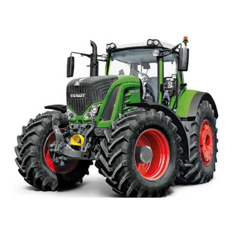
FENDT Vario 700 Series User manual

FENDT
FENDT 1149MT User manual
FENDT
FENDT New Leader NL5258G5 User manual
FENDT
FENDT New Leader NL4330G4 User manual

FENDT
FENDT 900 Vario Gen6 Series User manual
FENDT
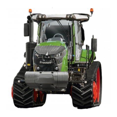
FENDT Vario MT 938 User manual

