FENDT Vario 900 Series User manual

Workshop Service Manual
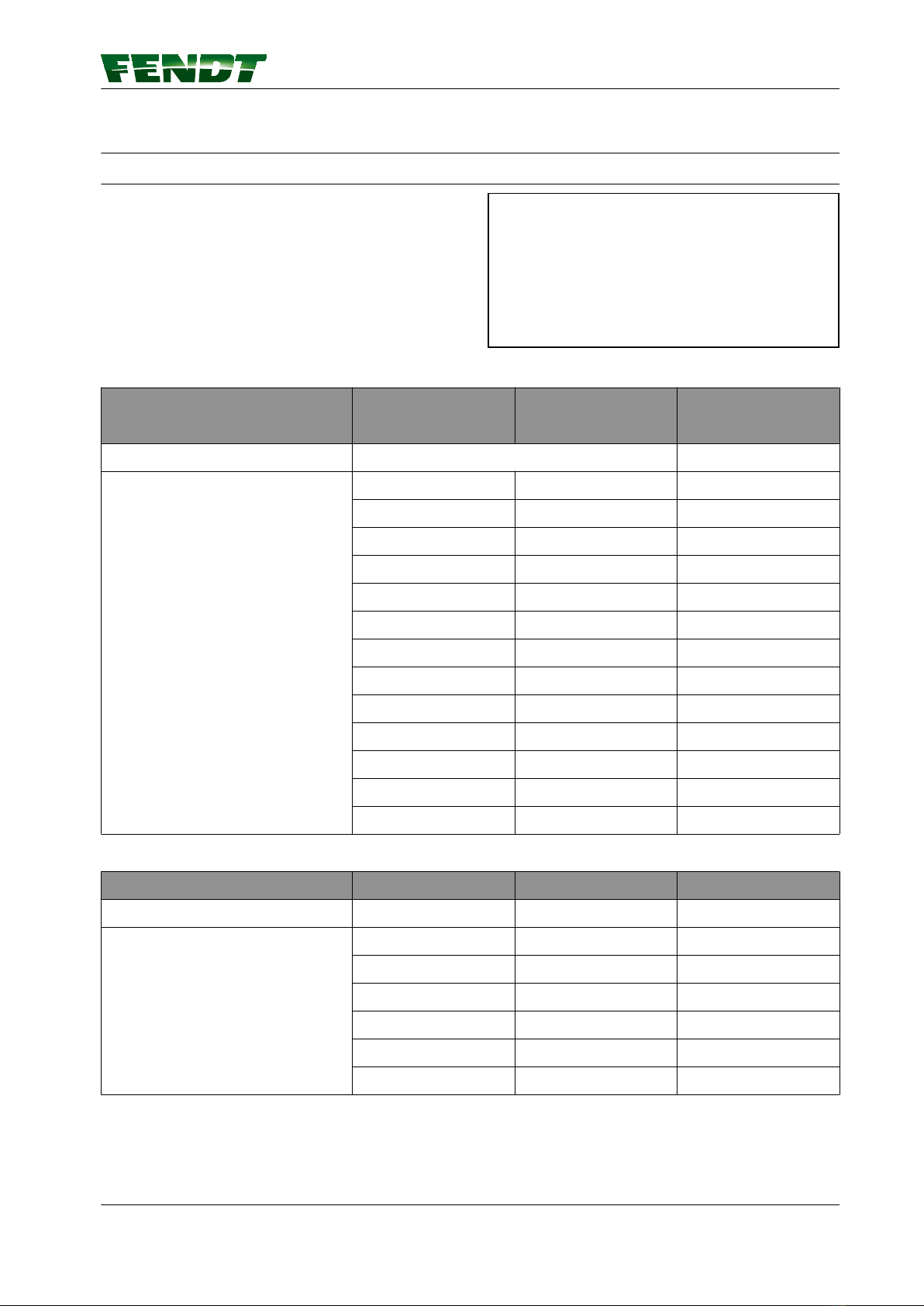
FENDT 900 Vario S4
FENDT 927 Vario S4
950 .. 1001-
FENDT 930 Vario S4
951 .. 1001-
FENDT 933 Vario S4
952 .. 1001-
FENDT 936 Vario S4
953 .. 1001-
FENDT 939 Vario S4
954 .. 1001-
Marktoberdorf
AGCO GmbH - Johann-Georg-Fendt-Str. 4 - D-87616
Marktoberdorf
FENDT is a worldwide brand of AGCO
© AGCO 2017
November 2017
X990.005.531.013
5201
EAME
English

Subject to changes and additions
IMPORTANT:
This document is valid from the chassis number noted. The last valid chassis number could not be
determined at the time of creation. Use AGCONET or contact FENDT technical service to make sure
whether a current wiring diagram set is available with an updated chassis number range.
Due to further developments to the vehicle, the content of this document is subject to change.
The relevant accident prevention regulations must be observed, as must as any generally acknowledged
safety, industrial medicine and traffic regulations. The manufacturer does not accept liability for damage
resulting from unauthorized modifications to the machine.
Property of AGCO GmbH.
Any disclosure to third parties—either in return for payment or free of charge—is prohibited.
GUID-A9F19094-7C5D-44B1-84C7-6D95E6AC44E4 [V2]
.
FENDT 900 Vario S4
X990.005.531.013
Find manuals at https://best-manuals.com

FENDT 900 Vario S4
1 00-000 Entire vehicle system .............................................. 1-1
1.1 General ........................................................... 1-5
1.1.1 Assignment table FENDT T types to the EU Type Approval Number ............1-5
1.1.2 Notes on documentation ...........................................1-6
1.1.3 Note on hydraulics ............................................... 1-7
1.1.4 Support points for jack and support stands ..............................1-7
1.2 Safety instructions .................................................1-8
1.2.1 Importance of and position of the safety decals .......................... 1-8
1.2.2 Work on the hydraulics ...........................................1-20
1.2.3 Working on the front axle suspension .................................1-20
1.2.4 Work on front/rear loader ..........................................1-22
1.2.5 Work on diesel engine and peripherals ................................1-24
1.2.6 Working on the PTO .............................................1-27
1.3 Tightening requirements ..........................................1-28
1.3.1 Spanner sizes for globally standard parts ...............................1-28
1.3.2 Tightening torque for screws with a galvanized surface ....................1-28
1.3.3 Tightening torque for screws and bolts with VDA coating ..................1-30
1.3.4 Tightening requirements for threaded plugs ............................1-30
1.3.5 Tightening requirements of banjo bolts ................................1-31
1.3.6 Tightening torques for hose clamps ..................................1-32
1.4 Fuels and lubricants ...............................................1-34
1.4.1 Biodiesel ......................................................1-34
1.4.2 Biodegradable hydraulic oil .........................................1-34
1.5 Technical specification ............................................1-36
1.5.1 Technical specification: Dimensions and weights ........................1-36
1.5.2 Technical specification: Gearbox .....................................1-40
1.5.3 Technical data: Diesel engine .......................................1-50
1.5.4 Technical specification: Front axle ...................................1-59
1.5.5 Technical data: Steering ...........................................1-62
1.5.6 Technical data: Chassis ...........................................1-64
1.5.7 Technical data: climate control and heating .............................1-75
1.5.8 Technical data: Wheels ...........................................1-76
1.5.9 Technical data: compressed air system ................................1-90
1.5.10 Technical data: Cab .............................................1-92
1.5.11 Technical data: Three-point linkage and lift system ......................1-92
1.5.12 Technical data: Front/rear loader ....................................1-94
1.5.13 Technical data: Electrical system ...................................1-97
1.5.14 Technical data: Hydraulics ........................................1-98
1.6 Fault code tables 800 / 900 Vario S4 .................................2-1
1.6.1 Fault code tables ............................................2-3
1.6.1.1 Confirming, calling up, deleting fault codes .......................2-3
1.6.1.2 Fault code 00.0.00 .........................................2-5
1.6.1.3 Fault code 01.0.00 .........................................2-9
1.6.1.4 Error code 02.1.00 ........................................2-16
1.6.1.5 Error code 03.1.00 ........................................2-18
1.6.1.6 Fault code 04.1.00 ........................................2-20
1.6.1.7 Fault code 05.1.00 ........................................2-33
1.6.1.8 Fault code 06.1.00 ........................................2-38
1.6.1.9 Fault code 07.1.00 ........................................2-43
1.6.1.10 Fault code 08.1.00 .......................................2-45
Table of contents
FENDT 900 Vario S4
X990.005.531.013
Find manuals at https://best-manuals.com

1.6.1.11 Fault code 09.1.00 .......................................2-51
1.6.1.12 Fault code 0A.1.00 .......................................2-56
1.6.1.13 Fault code 0B.1.00 .......................................2-75
1.6.1.14 Error code 0D.1.00 .......................................2-78
1.6.1.15 Fault code 0E.1.00 .......................................2-81
1.6.1.16 Error code 0F.1.00 .......................................2-86
1.6.1.17 Fault code 10.1.00 .......................................2-90
1.6.1.18 Error code 12.1.00 .......................................2-91
1.6.1.19 Fault code 15.1.00 .......................................2-99
1.6.1.20 Fault code 17.1.00 ......................................2-100
1.6.1.21 Fault code 18.01.00 .....................................2-101
1.6.1.22 Fault code 1A.1.00 ......................................2-104
1.6.1.23 Fault code 1D.1.00 ......................................2-109
1.6.1.24 Fault code 1F.1.00 ......................................2-121
1.6.1.25 Error code 20.1.00 ......................................2-122
1.6.1.26 Calibration fault codes ....................................2-127
1.7 Component position .............................................1-137
1.7.1 Electrical/electronic components - A .................................1-137
1.7.2 Electrical/electronic components - B .................................1-147
1.7.3 Electrical/electronic components - E .................................1-162
1.7.4 Electrical/electronic components - F .................................1-173
1.7.5 Electrical/electronic components - G .................................1-173
1.7.6 Electrical/electronic components - H .................................1-174
1.7.7 Electrical/electronic components – K .................................1-176
1.7.8 Electrical/electronic components - M ................................1-179
1.7.9 Electrical/electronic components - R .................................1-183
1.7.10 Electrical/electronic components - S ................................1-184
1.7.11 Electrical/electronic components – U ...............................1-192
1.7.12 Electrical/electronic components - X (0001–1000) ......................1-193
1.7.13 Electrical/electronic components - X (1001–2000) ......................1-197
1.7.14 Electrical/electronic components - X (2001–4000) ......................1-202
1.7.15 Electrical/electronic components - X (4001–6000) ......................1-203
1.7.16 Electrical/electronic components - Y ................................1-239
1.7.17 Hydraulic components ..........................................1-251
1.8 Calibrations ......................................................1-292
1.8.1 Adjustments — General ..........................................1-292
1.8.1.1 Calibration notes .........................................1-292
1.8.2 Adjustments — Gearbox .........................................1-292
1.8.2.1 Calibration 4001 clutch pedal ................................1-292
1.8.2.2 Calibration 4002: Hand throttle ..............................1-295
1.8.2.3 Calibration 4003: Travel range selector .........................1-298
1.8.2.4 Calibration 4005 driving pedal ...............................1-302
1.8.2.5 Calibration 4007: Transmission ratio characteristic ................1-304
1.8.2.6 Calibration 4009: Turbo-clutch function ........................1-308
1.8.2.7 Calibration 4010 driving pedal resolution .......................1-312
1.8.3 Adjustments — Sensors and functions ...............................1-315
1.8.3.1 Calibration 1001 crossgate lever .............................1-315
1.8.3.2 Calibration 1003/1004/1005/1006 Linear modules .................1-321
1.8.3.3 Calibration 2401 steering angle sensor .........................1-325
1.8.3.4 Calibration 2401 - checking the calibration accuracy ...............1-329
1.8.3.5 Calibration 2403: Steering valve, when required. ..................1-331
1.8.3.6 Calibration 6034: Rear PTO clutch ............................1-335
1.8.3.7 Calibration 7034 front PTO clutch ............................1-338
1.8.3.8 Calibration 7666: Front axle suspension ........................1-341
1.8.3.9 Calibration 8001 rear EPC - depth control .......................1-344
1.8.3.10 Calibration 8002: Rear EPC - position control ...................1-347
1.8.3.11 Calibration 9001 front EPC - depth control .....................1-351
1.8.3.12 Calibration 9002 front EPC - position control ....................1-354
Table of contents
FENDT 900 Vario S4
X990.005.531.013
Find manuals at https://best-manuals.com

1.8.3.13 Heating valve calibration - automatic air-conditioning system ........1-357
1.8.3.14 Speed display calibration ..................................1-359
1.9 Calibrations fault code ............................................1-362
1.9.1 Calibration fault code 1001 ........................................1-362
1.9.2 Calibration fault code 1003 ........................................1-362
1.9.3 Calibration fault code 1004 ........................................1-362
1.9.4 Calibration fault code 1005 ........................................1-363
1.9.5 Calibration fault code 1006 ........................................1-363
1.9.6 Calibration fault code 2401 ........................................1-363
1.9.7 Calibration fault code 2403 ........................................1-364
1.9.8 Calibration fault code 4001 ........................................1-364
1.9.9 Calibration fault code 4002 ........................................1-365
1.9.10 Calibration fault code 4003 .......................................1-365
1.9.11 Calibration fault code 4005 .......................................1-366
1.9.12 Calibration fault code 4007 .......................................1-366
1.9.13 Calibration fault code 4009 .......................................1-368
1.9.14 Calibration fault code 4010 .......................................1-369
1.9.15 Calibration fault code 7666 .......................................1-370
1.9.16 Calibration fault code 8001 .......................................1-370
1.9.17 Calibration fault code 8020 .......................................1-370
1.9.18 Calibration fault code 8021 .......................................1-371
1.9.19 Calibration fault code 8022 .......................................1-371
1.9.20 Calibration fault code 8023 .......................................1-371
1.9.21 Calibration fault code 9001 .......................................1-372
1.9.22 Calibration fault code 9002 .......................................1-372
1.9.23 Tire circumference calibration fault code .............................1-372
1.9.24 Heater valve calibration fault code .................................1-372
3 01-000 Engine, fuel and exhaust system ....................................3-1
3.1 General ........................................................... 3-3
3.1.1 Engine horsepower: comparison of standards and directives .................3-3
3.1.2 General description of the common rail system ...........................3-4
3.1.3 PTO power measurement ..........................................3-5
3.2 motor .............................................................3-8
3.2.1 Faults .........................................................3-8
3.2.2 Read out the Trip Recorder (load spectrum) using Serdia diagnostics ..........3-19
3.2.3 Automatic calibration of injectors ZFL .................................3-26
3.2.4 Deutz TCD 6.1/7.8 engines: Read out fault memory ......................3-34
3.2.5 Calculating the fuel consumption of a diesel engine .......................3-45
3.2.6 AdBlue® - and fuel consumption (emission level 4, Tier 4f) ..................3-53
3.2.7 Compression test with SerDia ......................................3-58
3.2.8 Compression test with compression pressure recorder ....................3-62
3.2.9 Crankcase pressure and ventilation ..................................3-68
3.2.10 Remove and replace the belt drive and tension pulley; repair the tension pulley . 3-75
3.3 Cylinder head .....................................................3-86
3.3.1 Valve adjustment (Deutz and AGCO Power engines) ......................3-86
3.3.2 Remove and install the injector and injector sleeve ......................3-101
3.4 Cooling system ..................................................3-128
3.4.1 Coolant circuit: Deutz TTCD 7.8 ....................................3-128
3.5 Fuel system ......................................................3-136
3.5.1 Pressure testing common rail system / fuel pre-filter / injector / dispensing unit /
high-pressure pump .................................................3-136
3.5.2 High-pressure accumulator: Common rail .............................3-180
3.5.3 Design and function of the high-pressure relief valve .....................3-181
3.5.4 High-pressure relief valve and rail pressure sensor: removal and installation ....3-182
3.5.5 Y095 to Y101 - Injectors 1 to 6 .....................................3-186
3.6 Lubrication ......................................................3-190
Table of contents
FENDT 900 Vario S4
X990.005.531.013
Find manuals at https://best-manuals.com

3.6.1 Schema: engine lubrication Deutz TTCD 7.8 L6 4V ......................3-190
3.7 Charge air and exhaust gas system ................................3-196
3.7.1 Design, operating conditions and cleaning .............................3-196
3.7.2 Fault analysis on exhaust gas return (AGRex) ..........................3-222
3.7.3 Function test of exhaust gas after-treatment system (DPF/SCR) with Serdia
diagnostics program .................................................3-229
3.7.4 Diesel particulate filter: Active regeneration and filter replacement ...........3-234
3.7.5 Decrystallization of the SCR exhaust system ...........................3-243
3.7.6 Fault analysis on A084 supply module/Y120 AdBlue flow valve (read faults/flush/
check SCR system) ..................................................3-253
3.7.7 SCR heater fault analysis .........................................3-286
4 02-000 Front axle .........................................................4-1
4.1 Front axle ......................................................... 4-3
4.1.1 Technical drawing: Wishbone arm ....................................4-3
4.1.2 Technical drawing: Planetary final drive and steering knuckle housing ...........4-9
4.1.3 Technical drawing: Suspension cylinder ...............................4-13
4.1.4 Technical drawing: Pinion shaft and differential ..........................4-15
4.1.5 Axle shaft with/without brake .......................................4-20
4.1.6 Removing front axle .............................................4-26
4.1.7 Disassemble and reassemble ZF suspension cylinder / replace mounting pins ...4-30
4.1.8 Check play in the front axle drive shaft ................................4-55
4.2 Suspension .......................................................4-64
4.2.1 Functional diagrams of front axle suspension ...........................4-64
4.3 Steering cylinder ..................................................4-70
4.3.1 Technical drawing: Steering cylinder and track rod ........................4-70
4.4 Cardan shaft ......................................................4-76
4.4.1 Technical drawing: Front-wheel drive shaft .............................4-76
5 03-000 Steering system ...................................................5-1
5.1 VarioGuide ........................................................5-3
5.1.1 Hardware architecture ............................................5-3
5.1.2 Wiring/cable sets ................................................5-5
5.1.3 Circuit diagram ..................................................5-7
5.1.4 Hydraulic check ..................................................5-8
5.1.5 A050 - basic control unit ECU (EXT) - VarioGuide .........................5-15
5.1.6 B067 - steering angle sensor .......................................5-18
5.1.7 B081 - steering wheel sensor (360°) ..................................5-22
5.1.8 Y085 - pilot pressure switch-off solenoid valve (VarioGuide) .................5-39
5.1.9 Y086 - steering disconnect solenoid valve (VarioGuide) ....................5-43
5.1.10 Y099 - pilot pressure switch-off solenoid valve (VarioGuide) ................5-47
6 04-000 Drive train .........................................................6-1
6.1 Gearbox control ................................................... 6-3
6.1.1 Transmission function diagram .......................................6-3
6.1.2 Position of transmission components (FENDT 900 Vario S4) .................6-9
6.1.3 ML260 transmission pressure measurement (fax template) .................6-21
6.1.4 Pressure measurement: Comfort hydraulics — Fax template (travel speed range I/
II, diff. lock, 4WD, rear PTO) ............................................6-42
6.2 Differential unit ...................................................6-49
6.2.1 RA 260 F rear axle: Removing and installing, dismantling, assembling and
adjusting the pinion shaft, differential and crown wheel. ........................6-49
6.3 Final drive axle ....................................................6-89
6.3.1 Disassemble and reassemble HA260F rear axle .........................6-89
6.4 Brake system ....................................................6-118
6.4.1 Remove and install rear-wheel brake and brake actuator (HA 260F) ..........6-118
Table of contents
FENDT 900 Vario S4
X990.005.531.013
Find manuals at https://best-manuals.com

6.4.2 Adjusting rear wheel brake ........................................6-148
6.4.3 Magnet setting for S005/S006 switch, right/left brake ....................6-153
6.5 Vario insert ......................................................6-156
6.5.1 Function of 2V3/2V4 high pressure relief valves .........................6-156
6.5.2 Function of flushing valve 2V5 .....................................6-157
6.5.3 Removing Vario insert ...........................................6-158
6.5.4 Fit the Vario insert ..............................................6-167
6.5.5 Install A009 actuator unit .........................................6-177
6.5.6 Change high pressure relief valves ..................................6-180
6.5.7 Replacing the flushing valve .......................................6-181
6.5.8 Top up the transmission oil .......................................6-183
6.5.9 Remove actuator shaft ...........................................6-183
6.5.10 Fit actuator shaft ..............................................6-186
6.5.11 Remove connecting rod .........................................6-190
6.5.12 Fit connecting rod .............................................6-192
6.5.13 Dismantle control housing .......................................6-195
6.5.14 Fit control housing .............................................6-196
6.6 Front PTO .......................................................6-199
6.6.1 Front PTO drawings .............................................6-199
6.6.2 Disassemble front PTO ..........................................6-207
6.6.3 Assemble front PTO ............................................6-219
6.6.4 Front PTO - check system pressure and clutch pressure, fax template ........6-232
6.7 Rear PTO ........................................................6-237
6.7.1 Disassembling and reassembling rear PTO gearbox (HA 260F) ..............6-237
6.8 Front wheel drive ................................................6-279
6.8.1 Dismantling and assembling the front-wheel drive clutch ..................6-279
6.9 Wheel weights ...................................................6-295
6.9.1 Fitting wheel weights: ...........................................6-295
7 05-000 Compressed-air system ............................................ 7-1
7.1 General ........................................................... 7-3
7.1.1 Compressed air pipes acc. to DIN 74324 ...............................7-3
7.1.2 Unlocking tool for compressed air pipes ................................7-3
7.1.3 Tightening torques for compressed air connection system .................. 7-3
7.2 Compressed-air system ............................................ 7-6
7.2.1 Compressed air comparison, single-circuit to dual-circuit brake system ......... 7-6
7.2.2 Compressed air compressor with energy saving system (ESS) ................7-7
7.2.3 Check oil consumption of compressed air compressor ....................7-14
7.2.4 Air dryer P2 with pressure controller ..................................7-17
7.2.5 4-circuit safety valve P4 ...........................................7-18
7.2.6 Pneumatic parking brake ..........................................7-27
7.2.7 "VarioGrip" tire pressure monitoring system, function and layout .............7-33
7.2.8 Check ABS (A086 ECU and Y160 solenoid valve) .........................7-55
7.2.9 Front wheel brake, rear wheel brake, parking brake .......................7-81
7.2.10 Adjust trailer control valve: Compressed air pilot control system and brake lead . 7-89
7.2.11 Synchronization of tractor and trailer .................................7-96
7.2.12 Dual-line brake: couplings between tractor and trailer ...................7-102
7.2.13 Tool for checking the tractor and trailer brake system ...................7-109
8 06-000 Hydraulic system .................................................. 8-1
8.1 Hydraulic equipment ...............................................8-3
8.1.1 Test report fax template - hydraulic pumps ..............................8-3
8.1.2 Functional plans: Generation of control pressure (pilot pressure) 22 bar ........8-14
8.1.3 Program valves .................................................8-19
8.1.4 External load sensing pressure rise (Power Beyond) ......................8-26
8.1.5 Removing rear hydraulic quick-release coupler ..........................8-27
Table of contents
FENDT 900 Vario S4
X990.005.531.013
Find manuals at https://best-manuals.com

8.1.6 Installing rear hydraulic quick-release coupler ...........................8-30
8.1.7 Seal hydraulic quick-release coupling .................................8-33
8.1.8 Front hydraulic connectors .........................................8-41
8.2 Hydraulic pumps ..................................................8-47
8.2.1 Function of LS pump (PR) (working and steering hydraulics) .................8-47
8.2.2 Drive LS pump, auxiliary pump, transmission servo pump and transmission
lubrication pump (technical drawing) ......................................8-54
8.2.3 Technical drawing: Pump drive for the PNL wheel-driven emergency steering
pump .............................................................8-64
8.2.4 Removing the LS pump ...........................................8-69
8.2.5 Installing the LS pump ............................................8-75
8.3 Hydraulic trailer brake .............................................8-82
8.3.1 Function of the hydraulic trailer brake (French and Italian versions) ............8-82
9 07-000 Electrical system ...................................................9-1
9.1 General ........................................................... 9-5
9.1.1 Component identification in accordance with DIN 40719 ....................9-5
9.1.2 Hall sensor operation ..............................................9-5
9.1.3 Button & switch functionality .......................................9-11
9.1.4 Rotary position sensor function, when used as a current divider ..............9-15
9.1.5 Pressure sensor function, when used as a current divider ..................9-20
9.2 Circuit diagrams ..................................................9-25
9.2.1 Circuit diagrams for A050 - basic control ECU ...........................9-25
9.3 Measure and test - A components ..................................9-32
9.3.1 A007 - instrument panel ...........................................9-32
9.3.2 A009 - actuator unit ..............................................9-44
9.3.3 Installing A009 actuator unit ........................................9-52
9.3.4 A011 - radar sensor ..............................................9-59
9.3.5 A013 - circuit board, microfuses .....................................9-62
9.3.6 A036 - "dashboard" control panel ....................................9-68
9.3.7 A038 - relay; +supply; K BUS .......................................9-72
9.3.8 A038 - head light, side light, direction indicator ..........................9-83
9.3.9 A038 - horn, rotating beacon, wide vehicle marker .......................9-89
9.3.10 A038 - work lights ..............................................9-91
9.3.11 A038 - interior lighting ...........................................9-94
9.3.12 A038 - mirror heating, rear window heating, windscreen heating; windscreen
wipers ............................................................9-96
9.3.13 A038 - automatic air conditioning system (heating, air conditioning, ventilation) . 9-100
9.3.14 A038 - sockets ...............................................9-106
9.3.15 A038 - Starter and tank pump .....................................9-115
9.3.16 A038 - reverse drive control (Rüfa) .................................9-118
9.3.17 A038 Work light activation .......................................9-124
9.3.18 Check A038 - central electrical system ECU with adapter box .............9-132
9.3.19 A050 - +supply ...............................................9-135
9.3.20 A050 - basic control unit ECU (EXT) Check with adapter box ..............9-141
9.3.21 A077 - immobilizer .............................................9-143
9.3.22 A082 - NOx1 nitrogen oxide sensor upstream of SCR ...................9-146
9.3.23 A083 - NOx2 nitrogen oxide sensor downstream of SCR .................9-147
9.3.24 A084 - AdBlue® module .........................................9-148
9.3.25 Check ABS (A086 ECU and Y160 solenoid valve) .......................9-152
9.3.26 A087 - tire pressure monitoring system (TPMS) ........................9-178
9.3.27 A099 - engine control unit .......................................9-180
9.3.28 A099 - engine control unit ECU (EDC 17) Check using adapter box ..........9-187
9.3.29 A100 - MFA, multifunction armrest .................................9-189
9.3.30 A100 - multifunction armrest (MFA) Check with adapter box ..............9-197
9.3.31 A133 air intake throttle ECU .....................................9-200
9.3.32 A134 - exhaust gas recirculation ECU ...............................9-201
Table of contents
FENDT 900 Vario S4
X990.005.531.013
Find manuals at https://best-manuals.com

9.3.33 A136 - wastegate ECU ..........................................9-202
9.3.34 A177 - AGCO Connectivity Module (ACM) ............................9-204
9.4 Measure and test - B components .................................9-205
9.4.1 B002 - front PTO speed sensor ....................................9-205
9.4.2 B004 - vacuum switch (air filter) ....................................9-206
9.4.3 B008 - high pressure sensor 1 .....................................9-208
9.4.4 B009 - discharge temperature sensor ................................9-210
9.4.5 B013 hydraulic oil temperature sensor ...............................9-211
9.4.6 B014 - collecting shaft sensor .....................................9-213
9.4.7 B015 - bevel pinion sensor ........................................9-215
9.4.8 B016 - travel speed range detection sensor ............................9-216
9.4.9 B017 clutch pedal sensor ........................................9-217
9.4.10 B019 - compressed air supply sensor, circuit 2 ........................9-218
9.4.11 B020 - rear PTO (stub shaft) speed sensor ...........................9-221
9.4.12 B021 - rear PTO clutch speed sensor ...............................9-222
9.4.13 B031 - right draft sensing pin .....................................9-223
9.4.14 B032 left-hand draft sensing pin sensor .............................9-224
9.4.15 B034 - Immersed tube fuel level sensor .............................9-226
9.4.16 B039 - high pressure sensor 2 ....................................9-228
9.4.17 B040 - front power lift position sensor ..............................9-230
9.4.18 B055 - foot throttle sensor .......................................9-231
9.4.19 B060 - compressed air supply sensor, circuit 1 ........................9-232
9.4.20 B066 - left wheel position sensor ..................................9-235
9.4.21 B067 - steering angle sensor .....................................9-237
9.4.22 B068 - right wheel position sensor .................................9-241
9.4.23 B071 - output temperature sensor .................................9-242
9.4.24 B073 - solar sensor (radiated heat) .................................9-244
9.4.25 B074 - interior temperature sensor .................................9-245
9.4.26 B076 - Outside temperature sensor ................................9-247
9.4.27 B078 - hand brake sensor ........................................9-248
9.4.28 B081 - steering wheel sensor (360°) ................................9-251
9.4.29 B084 - hydraulic oil level sensor ...................................9-253
9.4.30 B085 - camshaft speed sensor ....................................9-255
9.4.31 B086 - rail pressure sensor .......................................9-258
9.4.32 B087 low fuel pressure sensor ....................................9-261
9.4.33 B088 - sensor, crankshaft speed ...................................9-263
9.4.34 B089 engine temperature sensor (Deutz) ............................9-266
9.4.35 B090 oil pressure sensor ........................................9-269
9.4.36 B091 - water in fuel sensor ......................................9-271
9.4.37 B092 - charge air pressure/temperature sensor ........................9-272
9.4.38 Guidelines for checking the B102 "immersed tube" fill level sensor for the AdBlue
.................................................................9-275
9.4.39 B102 - AdBlue temperature/level sensor .............................9-279
9.4.40 B105 - exhaust gas temperature upstream of SCR sensor ................9-282
9.4.41 B145 - rear power lift position sensor ...............................9-284
9.4.42 B191 exhaust gas pressure sensor - upstream of turbo ..................9-285
9.4.43 B192 - CSF differential pressure sensor .............................9-286
9.4.44 B193 - exhaust temperature upstream of CSF sensor ...................9-288
9.4.45 B194 - pressure downstream of CSF sensor ..........................9-290
9.4.46 B217 temperature sensor downstream of venturi ......................9-291
9.4.47 B218 venturi differential pressure sensor ............................9-293
9.4.48 B283 - compressed air supply sensor, circuit 2 ........................9-294
9.4.49 B284 - compressed air supply sensor, circuit 1 ........................9-296
9.4.50 B290 - brake pedal lock sensor ....................................9-299
9.5 Measure and test - CAN bus ......................................9-301
9.5.1 CAN BUS ....................................................9-301
9.6 Measure and test - E components .................................9-307
Table of contents
FENDT 900 Vario S4
X990.005.531.013
Find manuals at https://best-manuals.com

9.6.1 E050 to E280 - work lights ........................................9-307
9.6.2 E216 - AdBlue heater suction and return line, E217 - AdBlue heater pressure line 9-308
9.7 Measure and test - G components .................................9-310
9.7.1 G001 battery ..................................................9-310
9.7.2 G002/G004 - right/left alternators ...................................9-311
9.8 Measure and test - H components .................................9-314
9.8.1 H005 - warning horn ............................................9-314
9.9 Measure and test - K components .................................9-315
9.9.1 K063 - Grid heater relay ..........................................9-315
9.9.2 K065 starter relay ..............................................9-316
9.9.3 K083 AdBlue relay ..............................................9-316
9.9.4 K090 AdBlue module heater relay ...................................9-317
9.9.5 K091 AdBlue heating relay for suction and return line ....................9-318
9.9.6 K092 AdBlue heating relay for pressure line ...........................9-318
9.10 Measure and test - M components ...............................9-319
9.10.1 M001 - starter ................................................9-319
9.10.2 M003/M005 - front/rear screen washer pumps ........................9-323
9.10.3 M004 - rear wiper motor ........................................9-324
9.10.4 M010 - fuel pump .............................................9-327
9.10.5 M015/M016 actuator motor for ventilation air flap ......................9-330
9.10.6 M017 - primary fan ............................................9-331
9.10.7 M046/M047 - headlight actuator motor (headlight adjustment) .............9-333
9.10.8 M048 - main fan ..............................................9-334
9.10.9 M049 - heater valve ...........................................9-336
9.10.10 M054 - cooling water pump .....................................9-338
9.10.11 M055 front wiper motor ........................................9-339
9.11 Measure and test - S components ................................9-341
9.11.1 S005/S006 - right/left brake switch .................................9-341
9.11.2 S017 filter contamination switch (transmission) ........................9-342
9.11.3 S019 - left external rear PTO button ................................9-343
9.11.4 S020 - right external rear PTO button ...............................9-344
9.11.5 S021 / S022 button, raise / lower external front power lift ................9-346
9.11.6 S025 - variable displacement pump pressure monitoring switch ............9-347
9.11.7 S027/S028/S029/S030 - external rear power lift button ..................9-349
9.11.8 S034 coolant level switch .......................................9-350
9.11.9 S035 High & low-pressure switch for air conditioning system ..............9-352
9.11.10 S045 reverse drive switch ......................................9-352
9.11.11 S047 - engine brake switch .....................................9-354
9.11.12 S053 driver seat switch ........................................9-354
9.11.13 S067 / S068 - left-hand external valve actuation button ..................9-355
9.11.14 S074 starter lockout switch .....................................9-357
9.11.15 S075 - wheel-driven steering pump flow-monitor switch ................9-358
9.11.16 S080 - hand brake switch .......................................9-359
9.11.17 S085 reverse drive (RÜFA) actuation switch .........................9-360
9.11.18 S119 - hydraulic oil filter contamination switch ........................9-362
9.11.19 S157 - forward/reverse shuttle switch ..............................9-362
9.11.20 S174/175 - right-hand external valve actuation button ...................9-364
9.12 Measure and test - X components ................................9-366
9.12.1 X007 - "black" implement socket ...................................9-366
9.12.2 X008 - counter input (onboard computer) "blue" ........................9-368
9.12.3 X015 - external control socket - External position sensor - rear EPC .........9-370
9.12.4 X015 - external control socket - 3rd and 4th hydraulic circuit ...............9-372
9.12.5 X015 - external control socket - Automatic steering axle mode .............9-373
9.12.6 X017 front socket (with front power lift only) ..........................9-376
9.12.7 X018 trailer socket .............................................9-377
9.12.8 X028 cab ISO socket ...........................................9-378
9.12.9 X400 ISO BUS PCB (implement socket) .............................9-379
Table of contents
FENDT 900 Vario S4
X990.005.531.013
Find manuals at https://best-manuals.com

9.12.10 X1048 ABS socket (anti-lock system on trailer) .......................9-389
9.12.11 X4407 - Air-conditioning system cable coupling .......................9-391
9.13 Measure and test - Y components ................................9-393
9.13.1 Y002 - travel speed range I solenoid valve ............................9-393
9.13.2 Y003 - travel speed range II solenoid valve ...........................9-394
9.13.3 Y004 clutch/turbo-clutch solenoid valve ..............................9-396
9.13.4 Y005 - speed governor solenoid valve ...............................9-397
9.13.5 Y008 - rear PTO (clutch) solenoid valve .............................9-399
9.13.6 Y009 - 4WD clutch solenoid valve ..................................9-400
9.13.7 Y010 - differential lock solenoid valve ...............................9-402
9.13.8 Y011 - front PTO clutch solenoid valve ..............................9-403
9.13.9 Y012 suspension loading/oil preheating solenoid valve ..................9-405
9.13.10 Y021 raise solenoid valve (standard front power lift) ...................9-406
9.13.11 Y021 - front pressure compensator lock valve ........................9-408
9.13.12 Y022 - lower front power lift solenoid valve ..........................9-409
9.13.13 Y026/Y027 - rear PTO stage I/II selection solenoid valve .................9-411
9.13.14 Y032 - control pressure solenoid valve .............................9-413
9.13.15 Y055 - rear pressure compensator lock valve .........................9-415
9.13.16 Y060 - hydraulic oil preheater solenoid valve .........................9-416
9.13.17 Y062 - rear ground pressure control solenoid valve ....................9-418
9.13.18 Y063 - wobble stabilizer solenoid valve .............................9-419
9.13.19 Y064 - Lower the solenoid valve on the suspension ....................9-421
9.13.20 Y065 - raise suspension solenoid valve .............................9-422
9.13.21 Y067 - lock suspension solenoid valve .............................9-424
9.13.22 Y082/Y083 - Lower link stabilizer lock and release solenoid valves .........9-425
9.13.23 Y084 - power beyond solenoid valve ...............................9-427
9.13.24 Y087 - VarioGuide steering valve ..................................9-428
9.13.25 Y091 fuel dispensing unit .......................................9-428
9.13.26 Y092/Y093 - reverse drive (RÜFA) rotation solenoid valves ...............9-430
9.13.27 Y095 to Y098, Y100, Y101 - injectors 1 to 6 ..........................9-432
9.13.28 Y120 - AdBlue® metering valve ...................................9-436
9.13.29 Y169 - AdBlue tank heater solenoid valve ...........................9-439
9.13.30 Y170 - exhaust brake solenoid valve ...............................9-440
9.13.31 Y172 - release control solenoid valve ...............................9-442
9.13.32 Y176 - Y185 Spool and control valves ..............................9-443
9.13.33 Y209 - reversible fan (Hägele) ....................................9-445
9.13.34 Y222 - Visco fan (Viscotronic) ....................................9-449
9.14 Measure and test - various components ..........................9-452
9.14.1 Camera .....................................................9-452
9.14.2 VarioGuide ..................................................9-455
10 08-000 Cab .............................................................10-1
10.1 Cab .............................................................10-3
10.1.1 Remove the cab ...............................................10-3
10.1.2 Attaching the cab ..............................................10-13
10.1.3 Remove and replace the cab roof ..................................10-20
10.1.4 Glue in the front windscreen .....................................10-26
10.1.5 Tightening torques of the door furniture .............................10-31
10.2 RÜFA — reverse drive ...........................................10-32
10.2.1 Reverse drive control function and operation ..........................10-32
10.2.2 Remove, install and repair turntable from operator's seat (Rüfa) ............10-36
10.2.3 Technical drawing of the turntable (reverse drive) ......................10-59
10.2.4 Seal the rotary feedthrough ......................................10-65
10.3 Driver seat ......................................................10-73
10.3.1 Operator's seat - overview of models ...............................10-73
10.3.2 Operator's seat - compressed air supply .............................10-74
10.3.3 Super Comfort - controls ........................................10-78
Table of contents
FENDT 900 Vario S4
X990.005.531.013

10.3.4 Evolution / Evolution Active - controls ...............................10-80
10.3.5 Evolution Active: Position of the electrical components ..................10-88
10.3.6 Evolution Active - height and weight adjustment .......................10-94
10.3.7 Evolution / Evolution Active - seat climate system .....................10-107
10.3.8 Evolution and Evolution Active - lumbar support .......................10-111
10.3.9 Evolution Active: Reset to delivery status ...........................10-114
10.3.10 Evolution Active - Adjust the suspension characteristic (mode) ...........10-115
10.3.11 Evolution Active – Adjust suspension characteristic (mode) using the
adjustment wheel ..................................................10-117
10.3.12 Evolution Active - seat suspension calibration .......................10-121
10.3.13 Evolution - Depth and tilt adjustment ..............................10-123
10.3.14 Evolution - left armrest, switch and backrest adjustment ...............10-133
10.3.15 Evolution - right armrest .......................................10-148
10.3.16 Evolution Active - suspension ...................................10-153
10.4 Air-conditioning system/heating ................................10-177
10.4.1 Overview ..................................................10-177
10.4.2 Advice .....................................................10-181
10.4.3 Evacuate and fill ..............................................10-182
10.4.4 Maintenance - air conditioning compressor drive belt tension .............10-183
10.4.5 Maintenance - Change the dryer module and filter .....................10-183
10.4.6 Check the functionality and performance ............................10-184
10.4.7 System pressure monitoring .....................................10-184
10.4.8 Check low pressure / high pressure ...............................10-185
10.4.9 Air conditioning unit service hatch .................................10-187
10.4.10 Removing the air conditioning unit (HVAC) ..........................10-189
10.4.11 Removing the air box (B071, M015, M016) .........................10-194
10.4.12 Installing the air box ..........................................10-197
11 12-000 Front power lift ..................................................11-1
11.1 Front power lift - valves ..........................................11-3
11.1.1 Hydraulic valves ...............................................11-3
11.1.2 Remove valve .................................................11-4
11.1.3 Install valve ...................................................11-9
12 13-000 Rear power lift ...................................................12-1
12.1 Electrohydraulic EPC control ......................................12-3
12.1.1 Slip control system .............................................12-3
12.1.2 EPC valves ...................................................12-4
12.1.3 Functional plans ...............................................12-7
12.1.4 Lower link stabilizer functional plan .................................12-19
12.1.5 Lower link stabilizer ............................................12-21
12.1.6 Remove EPC valve ............................................12-24
12.1.7 Fit the rear EPC valve ...........................................12-27
12.1.8 Dismantle the rear DW pressure limiting valve - Y062 ...................12-32
12.1.9 Fit the rear DW pressure relief valve Y062 ...........................12-33
12.1.10 Rear power lift - Seal lift cylinder ..................................12-35
12.2 Three-point linkage - lower link stabilizer .........................12-40
12.2.1 Lower link stabilizer ............................................12-40
12.2.2 Lower link stabilizer - Y082/Y083 ..................................12-43
13 20-000 Service ..........................................................13-1
13.1 Assembly instructions ............................................13-3
13.1.1 Exhaust brake X990.006.978.000 ...................................13-3
13.1.1.1 Overview of parts kit ......................................13-3
13.1.1.2 Engine brake installation ...................................13-4
13.1.2 Reversible fan X990.006.976.000 ..................................13-10
13.1.2.1 Overview of parts kit .....................................13-10
Table of contents
FENDT 900 Vario S4
X990.005.531.013

13.1.2.2 Mount the reversible fan ..................................13-11
13.1.2.3 Mounting, pneumatic and electrical actuation ...................13-16
13.1.3 Adjusting the axial play and sealing the double drive shaft X990.006.928.000 ..13-19
13.1.3.1 Technical drawings: planetary final drive .......................13-19
13.1.3.2 Adjustment of clearance and sealing of the double joint drive shaft of
the planetary final drive ..........................................13-23
13.1.3.3 Fitting tool ............................................13-42
13.1.4 Change steering cylinder guide bush X990.006.929.000 ..................13-43
13.1.4.1 Identification of front axle types DANA ........................13-43
13.1.4.2 Overview of the steering cylinder parts kit for replacing the guide bush 13-44
13.1.4.3 Technical drawings for steering cylinder .......................13-46
13.1.4.4 Replace steering cylinder guide bush .........................13-50
13.1.5 Single-line brake X990.006.958.000 ................................13-69
13.1.5.1 General task ...........................................13-69
13.1.5.2 Fitting ...............................................13-70
13.1.5.3 Check the single-line air brake (1) (1) .........................13-73
13.1.6 Repair wiring harness X990.006.968.000 ............................13-74
13.1.6.1 Repair the wiring harness (U954.200.300.000) ..................13-74
13.1.7 Retrofit hands-free device X990.006.945.000 .........................13-86
13.1.7.1 Overview of parts kit .....................................13-86
13.1.7.2 Assembly of the hands-free device ..........................13-87
13.1.7.3 Installation: Vario 800/900 .................................13-92
13.1.8 Rebuild headlight adjustment for LED headlamps X990.006.936.000 ........13-93
13.1.8.1 Retrofitting the LED headlamp leveling system ..................13-93
13.1.8.2 Retrofitting the LED headlamp leveling system ..................13-94
13.1.8.3 Adjust the front headlamps ...............................13-101
13.2 Special tools ...................................................13-103
13.2.1 Special tools ................................................13-103
Table of contents
FENDT 900 Vario S4
X990.005.531.013

Table of contents
FENDT 900 Vario S4
X990.005.531.013

1. 00-000 Entire vehicle system
1.1 General ................................................................1-5
1.1.1 Assignment table FENDT T types to the EU Type Approval Number .................1-5
1.1.2 Notes on documentation ................................................1-6
1.1.3 Note on hydraulics ....................................................1-7
1.1.4 Support points for jack and support stands ...................................1-7
1.2 Safety instructions ......................................................1-8
1.2.1 Importance of and position of the safety decals ...............................1-8
1.2.2 Work on the hydraulics ................................................1-20
1.2.3 Working on the front axle suspension ......................................1-20
1.2.4 Work on front/rear loader ...............................................1-22
1.2.5 Work on diesel engine and peripherals .....................................1-24
1.2.6 Working on the PTO ..................................................1-27
1.3 Tightening requirements ...............................................1-28
1.3.1 Spanner sizes for globally standard parts ....................................1-28
1.3.2 Tightening torque for screws with a galvanized surface .........................1-28
1.3.3 Tightening torque for screws and bolts with VDA coating .......................1-30
1.3.4 Tightening requirements for threaded plugs .................................1-30
1.3.5 Tightening requirements of banjo bolts .....................................1-31
1.3.6 Tightening torques for hose clamps .......................................1-32
1.4 Fuels and lubricants ....................................................1-34
1.4.1 Biodiesel ...........................................................1-34
1.4.2 Biodegradable hydraulic oil ..............................................1-34
1.5 Technical specification .................................................1-36
1.5.1 Technical specification: Dimensions and weights .............................1-36
1.5.2 Technical specification: Gearbox ..........................................1-40
1.5.3 Technical data: Diesel engine ............................................1-50
1.5.4 Technical specification: Front axle ........................................1-59
1.5.5 Technical data: Steering ................................................1-62
1.5.6 Technical data: Chassis ................................................1-64
1.5.7 Technical data: climate control and heating ..................................1-75
1.5.8 Technical data: Wheels ................................................1-76
1.5.9 Technical data: compressed air system .....................................1-90
1.5.10 Technical data: Cab ..................................................1-92
1.5.11 Technical data: Three-point linkage and lift system ........................... 1-92
1.5.12 Technical data: Front/rear loader .........................................1-94
1.5.13 Technical data: Electrical system ........................................1-97
1.5.14 Technical data: Hydraulics .............................................1-98
1.6 Fault code tables 800 / 900 Vario S4 ......................................2-1
1.6.1 Fault code tables .................................................2-3
1.6.1.1 Confirming, calling up, deleting fault codes ............................2-3
1.6.1.2 Fault code 00.0.00 ..............................................2-5
1.6.1.3 Fault code 01.0.00 ..............................................2-9
1.6.1.4 Error code 02.1.00 .............................................2-16
1.6.1.5 Error code 03.1.00 .............................................2-18
1.6.1.6 Fault code 04.1.00 .............................................2-20
1.6.1.7 Fault code 05.1.00 .............................................2-33
1.6.1.8 Fault code 06.1.00 .............................................2-38
1.6.1.9 Fault code 07.1.00 .............................................2-43
1.6.1.10 Fault code 08.1.00 ............................................2-45
Table of contents
FENDT 900 Vario S4 1-1
X990.005.531.013

1.6.1.11 Fault code 09.1.00 ............................................2-51
1.6.1.12 Fault code 0A.1.00 ............................................2-56
1.6.1.13 Fault code 0B.1.00 ............................................2-75
1.6.1.14 Error code 0D.1.00 ............................................2-78
1.6.1.15 Fault code 0E.1.00 ............................................2-81
1.6.1.16 Error code 0F.1.00 ............................................2-86
1.6.1.17 Fault code 10.1.00 ............................................2-90
1.6.1.18 Error code 12.1.00 ............................................2-91
1.6.1.19 Fault code 15.1.00 ............................................2-99
1.6.1.20 Fault code 17.1.00 ...........................................2-100
1.6.1.21 Fault code 18.01.00 ..........................................2-101
1.6.1.22 Fault code 1A.1.00 ...........................................2-104
1.6.1.23 Fault code 1D.1.00 ...........................................2-109
1.6.1.24 Fault code 1F.1.00 ...........................................2-121
1.6.1.25 Error code 20.1.00 ...........................................2-122
1.6.1.26 Calibration fault codes .........................................2-127
1.7 Component position ..................................................1-137
1.7.1 Electrical/electronic components - A ......................................1-137
1.7.2 Electrical/electronic components - B ......................................1-147
1.7.3 Electrical/electronic components - E ......................................1-162
1.7.4 Electrical/electronic components - F ......................................1-173
1.7.5 Electrical/electronic components - G ......................................1-173
1.7.6 Electrical/electronic components - H ......................................1-174
1.7.7 Electrical/electronic components – K ......................................1-176
1.7.8 Electrical/electronic components - M .....................................1-179
1.7.9 Electrical/electronic components - R ......................................1-183
1.7.10 Electrical/electronic components - S .....................................1-184
1.7.11 Electrical/electronic components – U ....................................1-192
1.7.12 Electrical/electronic components - X (0001–1000) ...........................1-193
1.7.13 Electrical/electronic components - X (1001–2000) ...........................1-197
1.7.14 Electrical/electronic components - X (2001–4000) ...........................1-202
1.7.15 Electrical/electronic components - X (4001–6000) ...........................1-203
1.7.16 Electrical/electronic components - Y .....................................1-239
1.7.17 Hydraulic components ...............................................1-251
1.8 Calibrations ...........................................................1-292
1.8.1 Adjustments — General ...............................................1-292
1.8.1.1 Calibration notes ..............................................1-292
1.8.2 Adjustments — Gearbox ..............................................1-292
1.8.2.1 Calibration 4001 clutch pedal .....................................1-292
1.8.2.2 Calibration 4002: Hand throttle ...................................1-295
1.8.2.3 Calibration 4003: Travel range selector ..............................1-298
1.8.2.4 Calibration 4005 driving pedal ....................................1-302
1.8.2.5 Calibration 4007: Transmission ratio characteristic .....................1-304
1.8.2.6 Calibration 4009: Turbo-clutch function .............................1-308
1.8.2.7 Calibration 4010 driving pedal resolution ............................1-312
1.8.3 Adjustments — Sensors and functions ....................................1-315
1.8.3.1 Calibration 1001 crossgate lever ..................................1-315
1.8.3.2 Calibration 1003/1004/1005/1006 Linear modules ......................1-321
1.8.3.3 Calibration 2401 steering angle sensor ..............................1-325
1.8.3.4 Calibration 2401 - checking the calibration accuracy ....................1-329
1.8.3.5 Calibration 2403: Steering valve, when required. .......................1-331
1.8.3.6 Calibration 6034: Rear PTO clutch .................................1-335
1.8.3.7 Calibration 7034 front PTO clutch .................................1-338
1.8.3.8 Calibration 7666: Front axle suspension .............................1-341
1.8.3.9 Calibration 8001 rear EPC - depth control ............................1-344
1.8.3.10 Calibration 8002: Rear EPC - position control ........................1-347
1.8.3.11 Calibration 9001 front EPC - depth control ..........................1-351
1.8.3.12 Calibration 9002 front EPC - position control .........................1-354
Table of contents
1-2 FENDT 900 Vario S4
X990.005.531.013

1.8.3.13 Heating valve calibration - automatic air-conditioning system .............1-357
1.8.3.14 Speed display calibration .......................................1-359
1.9 Calibrations fault code .................................................1-362
1.9.1 Calibration fault code 1001 .............................................1-362
1.9.2 Calibration fault code 1003 .............................................1-362
1.9.3 Calibration fault code 1004 .............................................1-362
1.9.4 Calibration fault code 1005 .............................................1-363
1.9.5 Calibration fault code 1006 .............................................1-363
1.9.6 Calibration fault code 2401 .............................................1-363
1.9.7 Calibration fault code 2403 .............................................1-364
1.9.8 Calibration fault code 4001 .............................................1-364
1.9.9 Calibration fault code 4002 .............................................1-365
1.9.10 Calibration fault code 4003 ............................................1-365
1.9.11 Calibration fault code 4005 ............................................1-366
1.9.12 Calibration fault code 4007 ............................................1-366
1.9.13 Calibration fault code 4009 ............................................1-368
1.9.14 Calibration fault code 4010 ............................................1-369
1.9.15 Calibration fault code 7666 ............................................1-370
1.9.16 Calibration fault code 8001 ............................................1-370
1.9.17 Calibration fault code 8020 ............................................1-370
1.9.18 Calibration fault code 8021 ............................................1-371
1.9.19 Calibration fault code 8022 ............................................1-371
1.9.20 Calibration fault code 8023 ............................................1-371
1.9.21 Calibration fault code 9001 ............................................1-372
1.9.22 Calibration fault code 9002 ............................................1-372
1.9.23 Tire circumference calibration fault code ..................................1-372
1.9.24 Heater valve calibration fault code ......................................1-372
Table of contents
FENDT 900 Vario S4 1-3
X990.005.531.013

Table of contents
1-4 FENDT 900 Vario S4
X990.005.531.013
1.1 General
1.1.1 Assignment table FENDT T types to the EU Type Approval Number
The EU type approval number consists of the
lower case letter "e" followed by the code letter or
number of the member state granting the EU type
approval. The FENDT T-type designation classifies
the relevant series and forms part of the 17-digit
vehicle identification number.
GUID-5D468356-C847-44EB-9323-D032399CEA06-high.jpg [High]
Fig. 1 Exemplary illustration
Series FENDT 200 Vario
V/F/P
FENDT 200 Vario FENDT 300 Vario
Type approval number e1*167/2013*00053 e1*167/2013*00054
Chassis numbers T232 T300 T347
T233 T301 T348
T234 T302 T349
T235 T303 T350
T236 T304
T239
T240
T241
T242
T243
T251
T252
T253
Series FENDT 500 Vario FENDT 700 Vario FENDT 800 Vario
Type approval number e1*167/2013*00042 e1*167/2013*00049 e1*167/2013*00047
Chassis numbers T435 T738 T839
T436 T739 T840
T437 T740 T841
T438 T741 T842
T742
T743
[V]
GUID-2D59C426-3B70-4D1B-A04F-E87356E798D1 [V2]
1. 00-000 Entire vehicle system
FENDT 900 Vario S4 1-5
X990.005.531.013

Series FENDT 900 Vario FENDT 1000 Vario
Type approval number e1*167/2013*00056 e1*167/2013*00055
Chassis numbers T950 T527
T951 T528
T952 T529
T953 T530
T954
1.1.2 Notes on documentation
To ensure that the information is structured in a user-friendly manner, the service documentation is divided
into the operator's manual and the workshop manual.
The operator's manual includes a general description as well as instructions for all necessary maintenance
work.
Knowledge of the owner's manual is essential to understand the workshop manual. This is particularly
important for safety instructions. The workshop manual describes repairs to assemblies and components
that will require more effort and suitably qualified specialists to carry out.
Note
This workshop manual provides notes for trained technicians to maintain our tractors. Read and observe
the information in this documentation. This will help you prevent accidents and safeguard the
manufacturer's warranty.
The respective accident prevention rules as well as other generally recognized safety and occupational
health rules must be observed.
The tractor is built solely for the purpose defined by the implement manufacturer. Any other type of use is
considered unauthorized. The manufacturer bears no liability for any damage resulting from improper use.
The user bears this risk alone. Intended use includes maintaining operating, service and maintenance
conditions as specified by the manufacturer.
Operation, maintenance and repair of the tractor may only be carried out by people who are familiar with
this equipment and aware of the associated dangers. Ensure that this documentation is available to and
understood by everyone involved in operation, maintenance and repair. Not observing this documentation
can lead to faults, damage and personal injury, for which the manufacturer assumes no liability. The
prerequisite for the tractor being correctly serviced and maintained is the perfect condition and availability
of all necessary equipment, standard tools and general workshop equipment as well as special tools.
Special tools must only be used where absolutely necessary. The tools are displayed where they need to
be used in each case.
The machine must be maintained according to its proper use. Always replace parts with genuine FENDT
spare parts! When ordering parts, please provide the chassis number as per the most up-to-date spare
parts documentation.
Only parts approved by the manufacturer for that specific purpose may be used for any alterations. The
manufacturer will not accept liability for any damage resulting from unauthorized modifications to the
tractor. Non-compliance invalidates the warranty!
Workshops should also refer to documentation on maintenance work and technical data. Once
maintenance is complete, take a test drive to ensure the vehicle's correct operation and road safety.
We reserve the right to make design changes in light of technical developments.
Notes on repairs
The assembly/disassembly instructions shown correspond to the design status at the time the workshop
manual was drawn up.
GUID-11DBEABB-D4B9-4CA8-9AD9-69470831C9ED [V2]
1. 00-000 Entire vehicle system
1-6 FENDT 900 Vario S4
X990.005.531.013
Other manuals for Vario 900 Series
1
This manual suits for next models
5
Table of contents
Other FENDT Tractor manuals

FENDT
FENDT Vario MT 938 User manual

FENDT
FENDT 1149MT User manual

FENDT
FENDT 938 Vario MT User manual

FENDT
FENDT 900 Vario Gen6 Series User manual

FENDT
FENDT 1149MT User manual

FENDT
FENDT Vario 900 Series User manual

FENDT
FENDT 5275 C User manual

FENDT
FENDT Vario 712 User manual

FENDT
FENDT New Leader NL4330G4 User manual

FENDT
FENDT 916 Vario User manual


